ISSN (Print) : 2320 – 3765 ISSN (Online): 2278 – 8875
I
nternational
J
ournal of
A
dvanced
R
esearch in
E
lectrical,
E
lectronics and
I
nstrumentation
E
ngineering
(An ISO 3297: 2007 Certified Organization)
Vol. 4, Issue 10, October 2015
Fuzzy Fan Controller Design and Simulation
Adnan Shaout
1, Adam Wilke
2Professor, Dept. of ECE, College of Engineering and Computer Science, the University of Michigan, Dearborn, USA1
G Student, Dept. of ECE, College of Engineering and Computer Science, the University of Michigan, Dearborn, USA2
ABSTRACT: A Variable Fill Fluid Coupling (VFFC)provides a way to control an engine fan without the stress that a mechanical gearbox can add, unfortunately VFFCs are very difficult to model mathematically. Because of this, a fuzzy controller for the VFFC is proposed. This controller will be validated and compared to a non-fuzzy solution via a MATLAB simulation. The simulation will allow for an easy comparison of different membership functions and defuzzification methods. The results from these simulations will show that a fuzzy controller can perform equivalently to a non-fuzzy controller. The results also suggest that through more refined tuning, a performance improvement over the non-fuzzy counter-part.
KEY WORDS: Variable Fill Fluid Coupling, Fuzzy Interface System (FIS), Fan Controller, Fuzzy Neural Network
I. INTRODUCTION
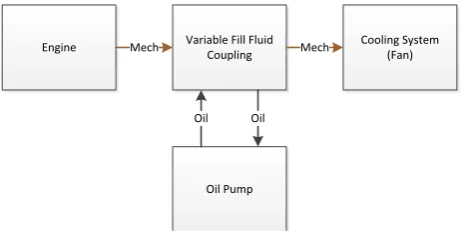
The goal of this paper is to design and analyze a fuzzy controller for a variable fill fluid coupling attenuated fan drive. A Variable Fill Fluid Coupling (VFFC) is a viscous torque converter whose output is determined by the volume of oil inside of it. By regulating the ratio of oil in versus oil out, the speed ratio can be controlled. This paper will validate the fuzzy controller through a fuzzy simulation of the fan drive and cooling system. MATLAB will be used to script and run the simulations. The simulation MATLAB code will allow for easy adjustment to various fuzzy properties of the system, including Membership Functions and Defuzzification Methods. The program will simulate a cooling system as shown in figure 1.
Figure 1 - System Architecture of a cooling system
There is significant research in the field of fuzzy systems and fuzzy controllers. Fuzzy PID controllers have been used to control a variety of systems, from electronic throttles [3] to cold plates [1]. There have also been many advancements to using fuzzy controllers. One significant improvement to fuzzy controllers is to make them a learning controller, through the use of a neural network or other methods [5]. A learning fuzzy controller can modify its fuzzy rule weights and membership functions to optimize the control while it is working. Other research has been done into combining regular fuzzy controllers and learning fuzzy controllers [4]. This has shown to improve performance by leveraging the efficiency of simple fuzzy controllers with the accuracy of learning fuzzy controllers.
This paper is organized into several sections. Section 2 of the paper presents a discussion on why Fuzzy was chosen for this control system and a comparison of fuzzy and non-fuzzy solutions to this problem. Then section 3 of the paper presents the proposed fuzzy inference system. Section 4 presents the simulation methodology. The results of the
Engine Variable Fill Fluid Coupling
Oil Pump
Cooling System (Fan)
Mech Mech
ISSN (Print) : 2320 – 3765 ISSN (Online): 2278 – 8875
I
nternational
J
ournal of
A
dvanced
R
esearch in
E
lectrical,
E
lectronics and
I
nstrumentation
E
ngineering
(An ISO 3297: 2007 Certified Organization)
Vol. 4, Issue 10, October 2015
simulations are presented after the simulation overview in section 5. The paper ends with a conclusion that sums up the major topics in section 6.
II. WHY FUZZY?
The fluid mechanics involved in a VFFC make modelling it’s mathematically difficult. For a given fluid type, the ratio of input to output rotational speed is dependent on the volume of oil in the coupling, the viscosity (a function of temperature) of the oil in the coupling, and the input speed. Rather than perform the Computational Fluid Dynamics (CFD) to try and identify the performance characteristics of a particular VFFC, a fuzzy control scheme is suggested. A fuzzy oil flow controller will allow for concise control of the cooling system without requiring the specifications for the VFFC.
2.1 Comparison of Fuzzy and Non-Fuzzy
Without a feedback loop on the cooling fan speed, a non-fuzzy system will struggle to determine the optimal amount of oil that should be flowed into the VFFC. Because the cooling system requires engine power to cool, finding the necessary amount of cooling to not over heat the system without overcooling and reducing engine performance is very important. A simple, purely mechanical non-fuzzy controller can be designed to provide sufficient cooling to the system, but to optimize engine performance, a more complicated controller is required. By utilizing fuzzy, a flexible controller that reacts to the current cooling needs of the systems to reduce over cooling can be implemented.
III. A VARIABLE FILL FLUID COUPLING FUZZY INFERENCE SYSTEM
The Variable Fill Fluid Coupling fuzzy inference system (FIS) uses two fuzzy input variables which are:
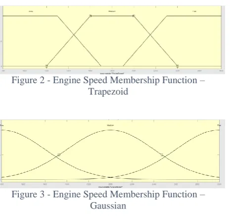
1- The Engine Speed with three linguistic fuzzy trapezoidal membership functions as shown in figure 2 or Gaussian membership functions as shown in figure 3, and
Figure 2 - Engine Speed Membership Function – Trapezoid
Figure 3 - Engine Speed Membership Function – Gaussian
2- The Coolant Temperature with three fuzzy
Trapezoidal Membership Function as shown in figure 4 or Gaussian as shown in figure 5.
Figure 4 - Coolant Temperature Membership Function – Trapezoid
Figure 5 - Coolant Temperature Membership Function – Gaussian
The Variable Fill Fluid Coupling fuzzy inference system has two fuzzy output variables as following:
1- The Oil Flow with three fuzzy Trapezoidal
ISSN (Print) : 2320 – 3765 ISSN (Online): 2278 – 8875
I
nternational
J
ournal of
A
dvanced
R
esearch in
E
lectrical,
E
lectronics and
I
nstrumentation
E
ngineering
(An ISO 3297: 2007 Certified Organization)
Vol. 4, Issue 10, October 2015
Figure 6 - Oil Flow Membership Function – Trapezoid
Figure 6 - Oil Flow Membership Function – Gaussian
2- The Cooling Amount with three fuzzy
Trapezoidal Membership Function as shown in figure 8 or Gaussian as shown in figure 9.
Figure 7 - Cooling Amount Membership Function – Trapezoid
Figure 8 - Cooling Amount Membership Function – Gaussian
Figure 10 shows the Fuzzy Rule Surface Plots for the Oil Controller with Trapezoidal MF and Centroid Defuzzification.
Figure 10 - Oil Controller Rule Surface - Trap MF, Centroid Defuzzification
Figure 11 shows the Cooling System Rule Surface with Trapezoidal MF and Centroid Defuzzification.
Figure 11 - Cooling System Rule Surface - Trap MF, Centroid Defuzzification
Figure 12 shows the Oil Controller Rule Surface with Gaussian MF and Centroid Defuzzification.
Figure 12 – Oil Controller Rule Surface – Gauss MF, Centroid Defuzzification
ISSN (Print) : 2320 – 3765 ISSN (Online): 2278 – 8875
I
nternational
J
ournal of
A
dvanced
R
esearch in
E
lectrical,
E
lectronics and
I
nstrumentation
E
ngineering
(An ISO 3297: 2007 Certified Organization)
Vol. 4, Issue 10, October 2015
Figure 13 – Cooling System Rule Surface – Gauss MF, Centroid Defuzzification
Figure 149 – Oil Controller Rule Surface – Trap MF, MoM Defuzzification
Figure 15 – Cooling System Rule Surface – Trap MF, MoM Defuzzification
IV. SIMULATION
MATLAB was used to simulate a fuzzy cooling system for the oil flow controller to interact with. There are four different MATLAB files (.m files) that comprise the simulation code. The MATLAB files are as follows:
AddEngineHeat.m - This function models heat being added to the system. If desired, the user can tweak the
curve used to determine the engine heat. It receives engine speed as an input, and it returns a temperature change.
CreateCoolingSystemFIS.m - This function creates the Fuzzy Interface System (FIS) that represents the Cooling System. It is a static script that should not be changed by the user. It receives definitions of the engine speed and oil flow linguistic terms, the fuzzy rule set that governs the Cooling System, as well as other fuzzy properties as its input. It returns a Cooling System FIS Object.
CreateOilCOntrollerFIS.m - This function creates the Fuzzy Interface System (FIS) that represents the Oil Controller. It is a static script that should not be changed by the user. It receives definitions of the engine speed and coolant temperature linguistic terms, the fuzzy rule set that governs the Oil Controller, as well as other fuzzy properties as its input. It returns an Oil Controller FIS Object.
CrispOilController.m - This code models a non-fuzzy oil controller. It represents a purely mechanical thermostatic oil flow controller. It controls the oil flow linearly per the coolant temperature, between some max and min. If desired, the user can tweak the control curve for the controller. It receives coolant temperature as an input, and it returns an oil flow.
Wilke_ECE552_Project.m - This is the main code for the simulation. It manages all of the fuzzy properties
and calls the CreateCoolingSystemFIS and CreateOilControllerFIS functions to generate FIS’s based on those properties. It also includes the main simulation loop that updates the coolant temperature at each time step. The simulation is set up to run through a range of predefined engine speed conditions and return the results as plots. The user can change any of the fuzzy properties, as well as changing the membership function values and types for each of the linguistic variables.
ISSN (Print) : 2320 – 3765 ISSN (Online): 2278 – 8875
I
nternational
J
ournal of
A
dvanced
R
esearch in
E
lectrical,
E
lectronics and
I
nstrumentation
E
ngineering
(An ISO 3297: 2007 Certified Organization)
Vol. 4, Issue 10, October 2015
Table 1 - Oil Controller Fuzzy Rules
IF THEN
Engine Speed Coolant Temp Oil Flow Rate
Slow Cold Low
Slow Warm Medium
Slow Hot Medium
Medium Cold Medium
Medium Warm Medium
Medium Hot High
Fast Cold Medium
Fast Warm High
Fast Hot High
Table 2 - Cooling System Fuzzy Rules
IF THEN
Engine Speed Oil Flow Rate Oil Flow Rate
Slow Low Low
Slow Medium Medium
Slow High Medium
Medium Low Medium
Medium Medium Medium
Medium High High
Fast Low Medium
Fast Medium High
Fast High High
V. SIMULATION RESULTS
The four different configurations that were simulated and compared were:
1. Crisp Controller
2. Fuzzy Controller, Trapezoid Membership Functions, Centroid Defuzzification Method
3. Fuzzy Controller, Gaussian Membership Functions, Centroid Defuzzification Method
4. Fuzzy Controller, Trapezoid Membership Functions, Mean of Maximum (MoM) Defuzzification Method
ISSN (Print) : 2320 – 3765 ISSN (Online): 2278 – 8875
I
nternational
J
ournal of
A
dvanced
R
esearch in
E
lectrical,
E
lectronics and
I
nstrumentation
E
ngineering
(An ISO 3297: 2007 Certified Organization)
Vol. 4, Issue 10, October 2015
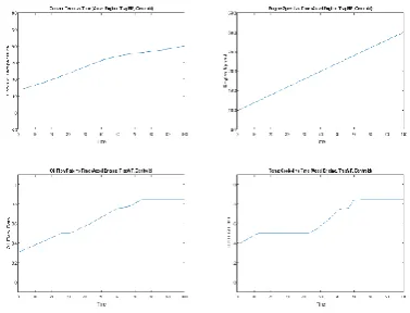
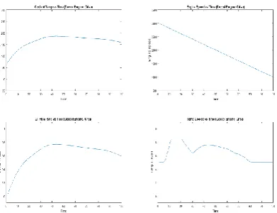
Figure 16 - Slow Engine Curve, Trapezoid MF, Centroid Defuzzification
Figure 17- Fast Engine Curve, Trapezoid MF, Centroid Defuzzification
Figure 18 - Acceleration Engine Curve, Trapezoid MF, Centroid Defuzzification
Figure 19 - Deceleration Engine Curve, Trapezoid MF, Centroid Defuzzification
Figure 20 - Slow Engine Curve, Gaussian MF, Centroid Defuzzification
ISSN (Print) : 2320 – 3765 ISSN (Online): 2278 – 8875
I
nternational
J
ournal of
A
dvanced
R
esearch in
E
lectrical,
E
lectronics and
I
nstrumentation
E
ngineering
(An ISO 3297: 2007 Certified Organization)
Vol. 4, Issue 10, October 2015
Figure 22 - Acceleration Engine Curve, Gaussian MF, Centroid Defuzzification
Figure 23 - Deceleration Engine Curve, Gaussian MF, Centroid Defuzzification
Figure 24 - Acceleration Engine Curve, Trapezoid MF, MoM Defuzzification
Figure 25 - Deceleration Engine Curve, Trapezoid MF, MoM Defuzzification
Figure 26 - Slow Engine Curve, Crisp Controller
ISSN (Print) : 2320 – 3765 ISSN (Online): 2278 – 8875
I
nternational
J
ournal of
A
dvanced
R
esearch in
E
lectrical,
E
lectronics and
I
nstrumentation
E
ngineering
(An ISO 3297: 2007 Certified Organization)
Vol. 4, Issue 10, October 2015
Figure 28 - Acceleration Engine Curve, Crisp Controller
Figure 29 - Deceleration Engine Curve, Crisp Controller
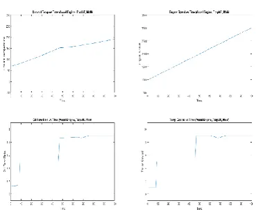
The Gaussian Fuzzy Controller had much smoother transitions through the Fuzzy Rules compared to the Trapezoid Fuzzy Controller as shown in figures 20 and 21. A side effect of this smoothness was a performance loss when compared to the Trapezoid Fuzzy Controller in most conditions. This smoothness is due to the shape of a Gaussian Membership Functions compared to that of a Trapezoid Membership Function.
The MoM Fuzzy Controller had a noticeably more jagged response than the Centroid Fuzzy Controllers as shown in figures 24 and 25. Depending on the engine speed, this had different impacts on the performance of the MoM Fuzzy Controller. For a constant engine speed, the MoM Fuzzy Controller performs similarly to the Centroid Fuzzy Controller. It sees a performance advantage on the acceleration and deceleration engine profiles. This is because the MoM Defuzzification Method causes the controller to react slower to rule changes, but in a more drastic way, so the controller will provide more cooling for longer than the other Centroid Fuzzy Controller.
VI. CONCLUSION
The objective of this paper was to design an engine fan controller for the prescribed system architecture, and compare the performance of a non-fuzzy and fuzzy controller. We also wanted to compare the effects that changing the different fuzzy properties have on the response of the controller. This was carried out through the use of a MATLAB simulation. The simulation had two components, the oil flow controller and the fuzzy cooling system. A crisp and a fuzzy controller were simulated, as well many simulations with various fuzzy properties. Although the results of the simulations did not show a significant performance improvement for the fuzzy controller, they did make it evident that the additional flexibility of a fuzzy solution could provide an improvement. The fuzzy controller could be refined and improved via additional iterations of the simulations or by implementing a learning method, such as a Fuzzy Neural Network, into the controller that can tune it as it runs for optimal efficiency.
REFERENCES
[1]R. Ushiyama and H. Walden, “Coldplate Temperature Regulation Using Fuzzy Logic Control,” in SAE Technical Paper 911559, 1991 © Society of Automotive Engineers, Inc.doi: 10.4271/911559
[2]A. Ismael et al., “Fuzzy Neural Network Implementation of Self Tuning PID Control Systems”,in “1994 IEEE International Symposium on Intelligent Control, 1994 © Institute of Electrical and Electronics Engineers, doi: 0-7803-1 990-7/94.
[3]X. Yuan et al., “Neural Network Based Self Learning Control Strategy for Electronic Throttle Valve,” in IEEE TRANSACTIONS ON VEHICULAR TECHNOLOGY, VOL 59, NO 8, 2010, pp. 3757-3765.