Power Factor Correction Using SEPIC
AC-DC Converter
Rachana V Murthy1, S Sridhar2,
PG Student [EPE], Dept. of EEE, RNS Institute of Technology, Bangalore, Karnataka, India1 Assistant Professor, Dept. of EEE, RNS Institute of Technology, Bangalore, Karnataka, India2
ABSTRACT: Usage of electronic devices like laptops, computers and mobile phones increased nowadays there is a need for AC to DC converters in Indian power supply as it is built with AC of 230V and 50 Hz frequency. So, a usage of rectifier bridge is increased in the powerlines. This causes third order harmonic injection in the line current which increases the reactive power. And power factor is also reduced at the supply side. In this project, a Single Ended Primary Inductor Converter (SEPIC) is used to inject the compensation current towards the supply to maintain power factor and Total Harmonic Distortion (THD). MATLAB is used to test the performance of the circuit. Hardware prototype is built for checking the performance
.
KEYWORDS: AC/DC converter, power factor correction, single-ended-primary inductor-converter (SEPIC).
I.INTRODUCTION
The input current harmonic content of AC-DC rectifiers followed by a bulk capacitor is very high and does not meet the international harmonic regulations and degrade the power factor at the mains. For that reason, a DC-DC converter at the DC-end of the rectifier is employed to make the input current track the input voltage profile through a correct control strategy. This strategy can be considered as an emulation of a pure resistive operation of the diode rectifier circuit. A converter with such a configuration is known as a power factor pre-regulator (PFP).
Different PFP configurations exist in the literature: the Buck, the Boost, the Buck-Boost, the Cuk , and the SEPIC topologies. The widely used PFP is a boost converter which has a simple topology in terms of power and control views . Nevertheless, Boost PFP suffers from difficult input-out high frequency isolation, output voltage higher than the peak input voltage, high starting current and no overload protection .
The control strategy in PFP can be realized in two approaches. The first is normally adopted with converters operating in continuous conduction mode (CCM), referred to as the multiplier approach. Two control loops are used; the external one controls the output voltage and the internal one ensures the wave shaping of the input current. This is achieved through multiplying the output of the voltage control loop by the input voltage to produce a sinusoidal reference current to the inner current loop.
The second approach is the voltage follower in which the converter operation is in discontinuous conduction mode (DCM), and only one simple voltage control loop is adopted to control the converter switching on time. In this scheme, the input current naturally tracks the sinusoidal line voltage waveform.
II.SYSTEM MODEL AND ASSUMPTIONS
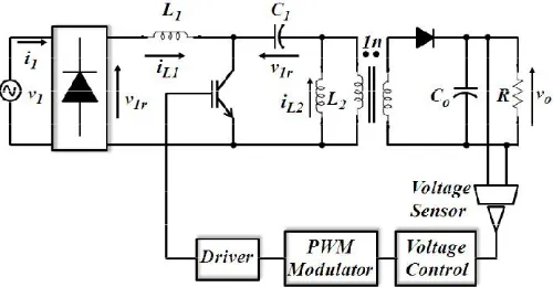
The basic configuration of an isolated SEPIC AC-DC converter is shown in Fig. 1. To ensure SEPIC PFP operation in DCM, the conduction parameter kα should be less than a critical value kα,crit . The following equations represent the
converter design criteria.
,
=
( )(1)
=
(2)
M =
v
= V |SinW t|
(3)
Where n is the transformer turn ratio, M is the output to peak input voltage ratio given by (3).
Fig. 1. Configuration of a single-phase AC-DC converter based on a SEPIC converter.
III.EFFICIENT COMMUNICATION
be considered in the output capacitor design. The following equation can be used to calculate both the high frequency output capacitor and the low frequency output capacitor .
IV.SECURITY
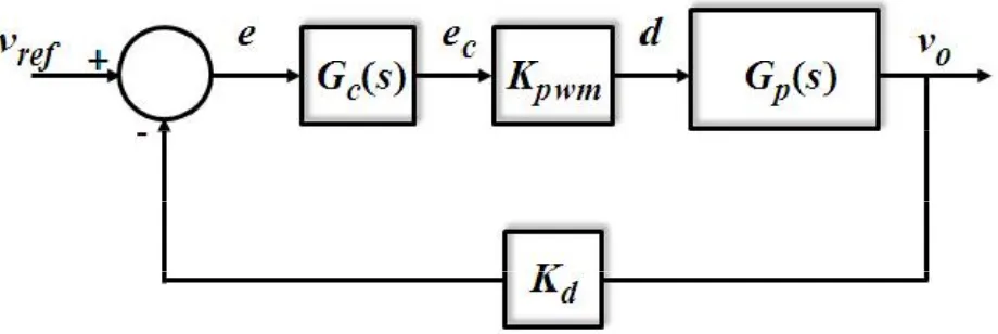
Fig. 2. Block diagram of the proposed control strategy
Figure 2 represents the voltage control block diagram of the SEPIC AC-DC converter. The output voltage is measured with a voltage sensor and compared with the desired magnitude. The error value (e) is utilized by a PI compensator to produce the desired control signal (ec) that is fed to the pulse width modulator (PWM) to generate the necessary driving
signal for the converter. The control to output transfer function (Gp(s))for the SEPIC APF converter operates in DCM
supplying resistive load can be modelled by a first order transfer function .The transfer functions of the PI compensator (GC(s)) and PWM (Kpwm) respectively. The voltage sensor gain Kd is adjusted by the designing.
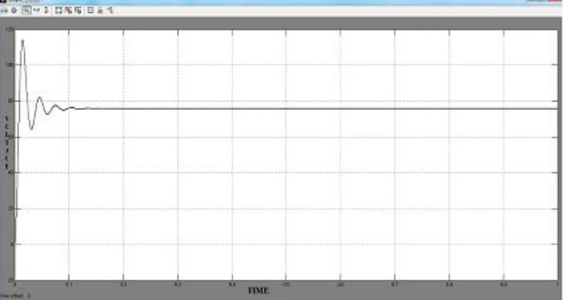
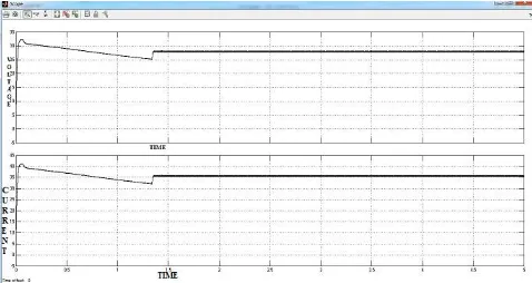
V. RESULT AND DISCUSSION
A Matlab/Simulink model is used to validate the design steps. Simulation will be performed considering step change in the line frequency, input voltage and the load.
Fig 3: Open Loop Simulation Circuit of SEPIC Converter
Fig 4: Closed Loop Simulation Circuit of SEPIC Converter
VI.CONCLUSION
In this paper, a single-phase isolated high power factor ac-dc converter based on a sepic dc-dc converter operating in dcm is presented. The input current tracks the input voltage profile naturally and the power factor is almost unity. Step by step design equations are presented to ensure converter operation in dcm over a wide range mains frequency. Numerical simulation has been conducted to confirm the design approach. Also, the converter performances are examined in terms of power factor, input current total harmonic distortion and output voltage regulation during transient and steady state conditions. The SEPIC PFP shows a satisfactory behaviour when subjected to disturbances in load, input voltage magnitude and the line frequency of the input voltage, all of which make this topology suitable for aircraft application.
REFERENCES
[1] B. S. Singh, B.N. ; Chandra, A. ; Al-Haddad, K. ; Pandey, A. ; Kothari, D., "A review of single-phase improved power quality AC-DC converters " IEEE Transactions on Idustrail Electronics, vol. 50, 2003.
[2] E. A. Oliveira, L. M. F. Morais, S. I. Seleme, P. F. Donoso-Garcia, P. C. Cortizo, and B. Cougo, "Power factor correction via passivity-based adaptive controller using buck converter operating in continuous mode," in Control and Modeling for Power Electronics, 2008. COMPEL 2008. 11th Workshop on, 2008, pp. 1-8.
[3] Q. Chongming and K. M. Smedley, "A topology survey of single-stage power factor corrector with a boost type input-current-shaper," IEEE Transactions on Power Electronics, vol. 16, pp. 360-368, 2001.
[4] P. Athalye, D. Maksimovic, and R. Erickson, "Variable-frequency predictive digital current mode control," Power Electronics Letters, IEEE, vol. 2, pp. 113-116, 2004.
[5] C. Jingquan, D. Maksimovic, and R. Erickson, "Buck-boost PWM converters having two independently controlled switches," in Power Electronics Specialists Conference, 2001. PESC. 2001 IEEE 32nd Annual, 2001, vol.2, pp. 736-741.
[6] E. Sehirli and M. Altinay, "Input-output linearization control of single-phase buck-boost power factor corrector," in 47th International Universities Power Engineering Conference (UPEC), 2012, pp. 1-6.
[7] D. S. L. Simonetti, J. Sebastian, F. S. dos Reis, and J. Uceda, "Design criteria for SEPIC and Cuk converters as power factor preregulators in discontinuous conduction mode," in Industrial Electronics, Control, Instrumentation, and Automation, 1992. Power Electronics and Motion Control., Proceedings of the 1992 International Conference on, 1992, vol.1, pp. 283-288.
[8] D. S. Lyrio Simonetti, J. Sebastian, and J. Uceda, "The discontinuous conduction mode Sepic and Cuk power factor preregulators: analysis and design," IEEE Transactions on Industrial Electronics, vol. 44, pp. 630-637, 1997.
[9] H. Y. Kanaan, K. Al-Haddad, G. Sauriole, and R. Chaffai, "Practical Design of a SEPIC Power Factor Corrector with DC-Voltage Regulation," in Industrial Electronics, 2006 IEEE International Symposium on, 2006, pp. 964-969.