PID CONTROLLER FOR SEMI-ACTIVE SUSPENSION SYSTEM USING MAGNETO-RHEOLOGICAL (MR) DAMPER
SARGESWARA RAJAN
A project report submitted in partial fulfillment of the requirements for the award of the degree of
Master of Mechanical (Engineering)
Faculty of Mechanical Engineering Universiti Teknologi Malaysia
This thesis work is dedicated to my wife, Logeswary, who has been a constant source of support and encouragement during the challenges of graduate school and life. I am truly thankful for having you in my life. This work is also
dedicated to my parents, Rajan and Paruvathy, who have always loved me unconditionally and whose good examples have taught me to work hard for
iv
ACKNOWLEDGEMENT
I am very fortunate to have performed my graduate work at a University Technology Malaysia; therefore, there are many people to thank for their part in my success.
Firstly I wish to thank my advisor, Dr. Intan Zaurah, for giving me an
opportunity to further this topic of studies under her supervision and support over the years. I am grateful for her guidance and the opportunities she has afforded me. She is incredibly organized and a great problem solver, both of these qualities were immensely helpful in moving my project forward. Under her mentorship I have learned the particulars of technical writing, which is an invaluable tool to have as my career moves forward. Dr.Intan is also exceptionally generous and would frequently take her students on outings to let us know our work is appreciated.
I would like to thank my friends for their continued support and
encouragement. Friends have been there for me when the challenges of graduate school seemed too great to overcome.
vi
ABSTRACT
ABSTRAK
viii
TABLE OF CONTENTS
CHAPTER TITLE PAGE
DECLARATION ii
DEDICATION iii
ACKNOWLEDGEMENT iv
ABSTRACT vi
ABSTRAK vii
TABLE OF CONTENTS viii
LIST OF TABLES xii
LIST OF FIGURES xiii
LIST OF SYMBOLS xvi
1 INTRODUCTION 1
1.1 Introduction 1
1.2 Research Background 2
1.3 Research Objectives 2
1.4 Problem Statement 3
1.5 Research Question 4
1.6 Theoretical Frame Work 4
1.7 Scope of Research 4
1.8 Research Methodology Flowchart 5
1.9 Gantt Chart 7
2 LITERATURE REVIEW 10
2.1 Introduction 10
2.2 Quarter Car Model 13
2.3 Classification of Vehicle Suspension System 13
2.3.1 Passive Suspension 14
2.3.2 Semi-active Suspension 15
2.3.3 Active Suspension 17
2.4 Magneto-Rheological(MR) Damper 18
2.4.1 Physical Study of MR Damper 19
2.4.2 MR Fluid Performance 23
2.4.3 MR Damper Dynamics 24
2.5 Suspension Control Strategies 27
2.5.1 Model Based Control 28
2.5.2 PID Controller 28
3 RESEARCH METHODOLOGY 33
3.1 Introduction 33
3.2 Model of The Car Suspension System 34
3.2.1 Passive Model Description 34
3.2.2 Mathematical Modeling for Passive Suspension System
35
3.2.3 Passive Suspension System in SIMULINK
36
3.3 Semi-Active Suspension System 37
3.3.1 Semi-active Model Description 37 3.3.2 Mathematical Modeling for Semi-active
Suspension System
39
3.3.3 Semi-active Suspension System in SIMULINK
40
3.4 MR Damper System 40
x
Identification
3.4.3 Comparison Between Model With Experimental Results
45
3.5 MR Damper Controller 46
3.5.1 Inner Loop Controller 46
3.5.2 Outer Loop Controller 47
3.5.3 PID Controller 48
3.5.4 PID Controller Tuning 49
3.5.5 Trial and Error Tuning Method 49 3.5.6 Ziegler-Nicholas Tuning Method 50 3.6 Implementation Using Matlab-SIMULINK 51
4 RESULTS 53
4.1 Introduction 53
4.2 Simulation Results for Step input 0.1 Road Disturbance
56
4.2.1 Analysis for Simulation Results of Step input 0.1 Road Disturbance
57
4.3 Simulation Result for Step input0.01 Road Disturbance
58
4.3.1 Analysis for Simulation Results of Step input 0.01 Road Disturbance
59
4.4 PID Tuning for Simulation 59
4.4.1 Ziegler-Nicholas Tuning Simulation 60 4.5 Simulation Result for Bumpy and Sinusoidal
Input
60
4.6 Simulation Results Analysis for Bumpy and Sinusoidal Input Road
63
5 DISCUSSION 65
5.2 Discussion of Performance for Step Input 65
6 CONCLUSION AND RECOMMENDATIONS 67
6.1 Introduction 67
6.2 Conclusion 67
6.3 Summary of Research Contribution 69
6.4 Recommendation for Future Works 69
xii
LIST OF TABLES
TABLE NO. TITLE PAGE
2.1 Parameters for PID tuning (Ziegler-Nicholas Method) 32 3.1 Passive Suspension System Parameters Identification 35 3.2 Semi-active Suspension System Parameters
Identification 39
3.3 Parameters for the MR damper model (H.F.Lam-2006) 43 3.4 Parameters of the PID Controller Calculated by
Ziegler-Nichols Method 51
4.1 Car Suspension System Parameters For Simulation 54
4.2 Simulation result of step input 0.1 57
4.3 Simulation result of step input 0.01 59
4.4 PID controller value 60
4.5
5.1
Simulation results analysis for bumpy and sinusoidal input road
Simulation comparison of body displacement and body acceleration between passive and semi-active system
58
LIST OF FIGURES
FIGURE NO. TITLE PAGE
1.1 Flowchart of Methodology 6
1.2 Gantt chart for Master Project 1 7
1.3 Gantt chart for Master Project 2 8
2.1 Model Passive Suspension 14
2.2 Model Semi-Active Suspensions 16
2.3 Model Active Suspensions 18
2.4 (a)MR damper (b)Piston 3D view 19
2.5 Functional representation of MR damper 20
2.6 Sectional view of MR damper 21
2.7 Close-up sectional identifying “choking regions” and
fluid gap 22
2.8 Actual Hardware 22
2.9 Phenomenological behavior of MR fluid 24
2.10 Linear Damper characteristic 25
2.11 Bilinear, asymmetric damping characteristics 25
2.12 Ideal MR damper performance 26
2.13 MR damping force envelope 27
2.14 Schematic of the PID controller applied in suspension
system 30
3.1 Passive suspension system model 34
3.2 SIMULINK modeling passive suspension systems 36
3.3 Block diagram of semi-active suspensions 38
3.4 Semi-active suspension model 38
xiv
3.6 MR Fluid in suspension model 41
3.7
3.8
Bouc-Wen modified MR damper model (Spencer-1997)
Force-displacement relation of MR Damper
42
44
3.9 Force-Velocity relation of MR Damper 45
3.10 Model Force-displacement relation of MR Damper 45 3.11 Model Force-Velocity relation of MR Damper 46 3.12 Control Algorithm for the input voltage of MR
Damper 47
3.13 Block Diagram of the PID Semi-Active suspension
System 48
3.14 Steady oscillation illustrating the ultimate period 50 3.15 SIMULINK model for semi-active and passive
suspension system 52
4.1(a) Step Input 54
4.1(b) Bumpy Input 55
4.1(c) Sinusoidal Input 55
4.2 Simulation Results of body displacement for Passive and Semi Active Suspension System for step input 0.1 56 4.3 Simulation Results of body acceleration for Passive
and Semi Active Suspension System for step input 0.1 56 4.4 Simulation Results of body displacement for Passive
and Semi Active Suspension System for step input
0.01 58
4.5 Simulation Results of body acceleration for Passive and Semi Active Suspension System for step input
0.01 58
4.6 Simulation Results of body displacement for Passive and Semi Active Suspension System for Bumpy input 61 4.7 Simulation Results of body acceleration for Passive
and Semi Active Suspension System for step input 61 4.8 Simulation Results of body displacement for Passive
Input 62
xvi
LIST OF SYMBOLS
ߙ - MR yield stress
ߛ - Hysteresis parameter
η - Equilibrium rate
ߚ - Hysteresis parameter
A - Hysteresis parameter
ܥ௨ - Damper constant at unsprung
ܿଵ - Reproduce the roll-off occurring ܿ - Viscous at large damping
F - Force generated
ܨௗ - Damping Force
ܨ - DesiredDamping Force
Hz Hertz
݇ - Stiffness at large velocities
݇ଵ - Stiffness due to accumulator
ܭ - Critical value of Proportional
ܭ௦ - Spring constant of Sprung(body) ܭ௨ - Spring constant of Unsprung(tire)
ܯ௦ - Mass of Sprung(body)
ܯ௨ - Mass of Unsprung(tire)
n - Number of turns
ܲ - Critical value of Period s, sec - Second
ܺ௦ - Displacement of Sprung(body)
ܺ௨ - Displacement of unsprung(tire)
ݔ - Damper displacement
V, Volt - Voltage
ݕ - Internal displacement of the damper
1 CHAPTER 1
INTRODUCTION
1.1 Introduction
2
There has been a sustained interesting magneto-rheological (MR) device due to the controllable interface provided by the MR fluid inside the devices that enables the mechanical device to interact with an electronic system, which can be used to continuously adjust the mechanical properties of the device. Some examples of devices in which MR fluids have been employed include dampers, clutches, brakes and transmissions.
The most popular of these devices are MR dampers, especially as automotive shock absorbers. The automotive shock absorber has been shown to be a very important contributor to the ride comfort and road handling of a vehicle. It can conclude that the success of MR damper in semi-active vehicle suspension applications is determined by two aspects which is the accurate modeling of the MR dampers and the other is the selection of an appropriate control strategy.
In addition ,theoretical and simulation researches have demonstrated that the performance of a semi-active control system is also highly dependent on the choice of control strategy .Therefore, some semi-active and passive control schemes have been discussed and compared the approaches ,such as PID controller into semi active control.
1.3 Research Objectives
3
ii. To investigate the performance of the controller for body displacement and body acceleration of semi-active system for various road condition.
1.4 Problem Statements
Traditionally, automotive suspension designs have been a compromise between the two conflicting criteria of road holding and passenger comfort. The suspension system must support the weight of the vehicle, provide directional control during handling maneuvers, and provide effective isolation of passengers and payload from road disturbances.
A passive suspension has the ability to store energy via a spring and to dissipate it via a damper. The parameters are generally fixed, being chosen to achieve a certain level of compromise between road holding and ride comfort. Once the spring has been selected based on the load-carrying capability of the suspension, the damper is the only variable remaining to specify. Low damping yields poor resonance control at the natural frequencies of the body (sprung mass) and axle (unsprung mass), but provides the necessary high frequency isolation required for a comfortable ride. Conversely, large damping results in good resonance control at the expense of high frequency isolation. Due to these conflicting demands, suspension design has had to be something of a compromise, largely determined by the type of use for which the vehicle is designed.
4 1.5 Research Question
Can PID controller using MR damper the vibration vibrations of automotive suspension system from various road conditions?
1.6 Theoretical Frame Work
This study is to design a robust controller to control a semi-active suspension system using quarter car model with MR damper.
1.7 Scopes of Research
The scopes of this project are:
i. Literature Review of semi-active suspension, modelling techniques and controllers, and MR damper.
ii. Modelling of semi-active suspension system using MR damper of a quarter car model within Matlab SIMULINK environment.
5
iv. Validation, verification and analysis of the controllers’ performance for semi-active suspension system using MR damper in comparison with passive suspension system.
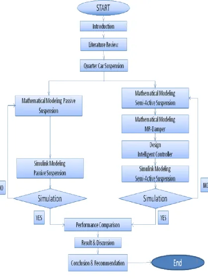
1.8 Research Methodology and Flowchart
The methodologies involved in this study are shown in Figure 1.1. The project starts by collecting reading materials such as books, journals and technical papers specifically on quarter car model, passive and semi-active suspension system, MR damper, intelligent controller.
Research has been done continuously throughout this study to get a better understanding on the concept of semi-active suspension system and its constraints. Besides, consultation sessions with the project supervisor and few colleagues who are doing similar research were also held periodically to discuss any arising issues and problems encountered pertaining to this study.
6
7
1.9 Gantt Chart
NO. ACTIVITIES
WEEKS
1 2 3 4 5 6 7 8 9 10 11 12 13 14 15 16
1 Selection of project title
2 Collecting reading materials
3 Literature review of previous research
4 Understanding the concept of semi-active
vehicle suspension system with MR damper
5 Familiarization with Matlab SIMULINK
6 Simulation of vibration environment using
data acquired by previous researcher
7 Simulation of semi-active vibration
controller
8 Analysis of the results from the simulation
of passive and semi-active
9 Report writing
10 Preparation for seminar presentation
8 1 Literature review
2 Experimental setup: Integration and
development of data acquisition and
instrumentation system
3 Experiment on vibrating mechanical
equipments (quarter car suspension)
4 Analysis of the experimental results
5 Report writing
6 Preparation for seminar presentation and
submission of draft thesis
7 Seminar 2
8 Submission of the thesis
9 1.10 Thesis Outline
This thesis consists of seven chapters. Chapter 1 is the introduction chapter. This chapter presents the research background, statement of the problem, objectives and scopes of the study, research contributions, methodology of research, and the overall outline of this thesis
Chapter 2 presents the literature review on related subjects concerning this thesis. In this chapter, the classification of vehicle suspension system, the selection of damper types and review on published articles related to active suspension control strategies are described.
Chapter 3 presents the methodology, modelling and validation of quarter car model. In this chapter, the mathematical equation of 2DOF quarter car model is introduced. Then, the mathematical model with quarter car is presented in order to validate the simulation results. The development of a validated quarter car model based on the mathematical quarter car is described. This chapter also presented the development of force tracking control system. In this chapter, a mathematical formulation of MR damper dynamics is introduced. Then, the algorithm of force tracking control system is formulated. Finally, the evaluation of force tracking control performance is discussed in terms of the tracking ability of the pneumatic force to the desired force.
10
controller is carried out using quarter with passive system.
70
REFERENCES
1. Nitish Katal, Sanjay Kr. Singh (2012). Optimization of PID Controller for Quarter-Car Suspension System using Genetic Algorithm. International Journal
of Advanced Research in Computer Engineering & Technology (IJARCET) Volume 1, Issue 7, September 2012. ISSN: 2278 – 1323
2. Mohammadjavad ,Z., Intan Zaurah ,M. D.(2012). Fuzzy P ID Controller Simulation for a Quarter-car Semi-active Suspension System Using. 2012 IEEE
Conference on Control, Systems and Industrial Informatics (ICCSII)Bandung, Indonesia, September 23-26, 2012.
3. Banna Kasemi *, Asan G. A. Muthalif , M. Mahbubur Rashid, Sharmila Fathima(2012). Fuzzy-PID Controller for Semi-Active Vibration Control Using Magnetorheological Fluid Damper. International Symposium on Robotics and
Intelligent Sensors 2012 (IRIS 2012).
4. Dyke, S.J., Spencer Jr., B.F. (1997). A Comparison of Semi-Active Control Strategies for the MR Damper. Proceedings of the IASTED International
Conference, Intelligent Information Systems, The Bahamas, Dec. 8–10, 1997.
5. T. Ram,M. R.,G. Venkata, R., k.Sreenivasa, R., A. Purushottam.(2010). Analysis Of Passive And Semi Active Controlled Suspension Systems For Ride Comfort In
An Omnibus Passing Over A Speed Bump. Department of Mechanical
Engineering, Vasavi College of Engineering, Hyderabad, India. IJRRAS 5 (1) ,October 2010.
71
7. Min,S. S., Seung,B. C.,Kum,G.S.(2011).Control Strategies for Vehicle Suspension System Featuring Magnetorheological (MR) Damper. Vibration
Analysis and Control - New Trends and Developments. Edited by Dr. Francisco Beltran-Carbajal.(2011).
8. Abdelhaleem, A. M., and Crolla, D. A., (2000). Analysis and Design of Limited
Bandwidth Active Hydropneumatic Vehicle Suspension Systems, SAE Technical
Paper Series, Paper No. 2000-01-1631
9. Appleyard, M., and Wellstead, P. E. (1995). Active Suspensions: Some
Background, IEE Proc. Control Theory Appl., Vol. 142, No. 2, pp.123-128
10. Elmadany, M. M., and Abduljabbar, Z. (1989). On The Statistical Performance
of Active And Semi-Active Car Suspension Systems, Computers & Structures,
Vol. 33, No. 3, pp.785-790
11. Fischer, D., and Isermann, R. (2004). Mechatronic Semi-Active and Active
Vehicle Suspensions, Control Engineering Practice, Vol. 12, pp.1353-1367
12. Hudha, K. (2005). Non-Parametric Modeling and Modified Hybrid Skyhook
Groundhook Control of Magnetorheological Dampers for Automotive Suspension
Systems, Universiti Teknologi Malaysia: PhD Thesis
13. Hudha, K., Jamaluddin, H., Samin, P. M., and Rahman, R. A. (2005). Effects of
Control Techniques and Damper Constraint on the Performance of a Semi-Active
Magnetorheological Damper, Int. J. Vehicle Autonomous Systems, Vol. 3, Nos.
72
14. Kumar, M. S., and Vijayarangan, S. (2007). Analytical and Experimental Studies
on Active Suspension System of Light Passenger Vehicle to Improve Ride
Comfort, Mechanika, Vol. 65, No. 3, pp.34-41
15. Nieto, A. J., Morales, A. L., Gonzáles, A., Chicharro, J. M., and Pintado, P.
(2008). An Analytical Model of Pneumatic Suspensions Based on an Experimental Characterization, Journal of Sound and Vibration, Vol. 313,
pp.290-307
16. Sam, Y. M., Osman, J. H. S., and Ghani, M. R. A. (2004). A Class of
Proportional-Integral Sliding Mode Control with Application to Active
Suspension System, Systems & Control Letters, Vol. 51, pp.217-223
17. Tamboli, J. A., and Joshi, S. G. (1999). Optimum Design of a Passive Suspension
System of a Vehicle Subjected to Actual Random Road Excitations, Journal of
Sound and Vibration, Vol. 219, No. 2, pp.193-205
18. Türkay, S., and Akçay, H. (2008). Aspects of Achievable Performance for
Quarter-Car Active Suspensions, Journal of Sound and Vibration, Vol. 311,
pp.440-460
19. Yoshimura, T., Kume, A., Kurimoto, M., and Hino, J. (2001). Construction of an
Active Suspension System of a Quarter Car Model Using The Concept of Sliding