University of Windsor University of Windsor
Scholarship at UWindsor
Scholarship at UWindsor
Electronic Theses and Dissertations Theses, Dissertations, and Major Papers
2016
An Engineered Installation Aid Device For Child Restraint System
An Engineered Installation Aid Device For Child Restraint System
to Mitigate Misuse
to Mitigate Misuse
Xinqi Chen
University of Windsor
Follow this and additional works at: https://scholar.uwindsor.ca/etd
Recommended Citation Recommended Citation
Chen, Xinqi, "An Engineered Installation Aid Device For Child Restraint System to Mitigate Misuse" (2016). Electronic Theses and Dissertations. 5806.
https://scholar.uwindsor.ca/etd/5806
This online database contains the full-text of PhD dissertations and Masters’ theses of University of Windsor students from 1954 forward. These documents are made available for personal study and research purposes only, in accordance with the Canadian Copyright Act and the Creative Commons license—CC BY-NC-ND (Attribution, Non-Commercial, No Derivative Works). Under this license, works must always be attributed to the copyright holder (original author), cannot be used for any commercial purposes, and may not be altered. Any other use would require the permission of the copyright holder. Students may inquire about withdrawing their dissertation and/or thesis from this database. For additional inquiries, please contact the repository administrator via email
An Engineered Installation Aid Device For Child Restraint System to Mitigate Misuse
By
Xinqi Chen
A Thesis
Submitted to the Faculty of Graduate Studies
through the Department of Mechanical, Automotive, and Materials Engineering
in Partial Fulfillment of the Requirements for the Degree of Master of Applied Science
at the University of Windsor
Windsor, Ontario, Canada
2016
AN ENGINEERED INSTALLATION AID DEVICE FOR CHILD RESTRAINT SYSTEM TO MITIGATE MISUSE
by
Xinqi Chen
APPROVED BY:
______________________________________________ B. Minaker
Department of Mechanical, Automotive, and Materials Engineering
______________________________________________ H. Hu
Department of Mechanical, Automotive, and Materials Engineering
______________________________________________ W. Altenhof, Advisor
Department of Mechanical, Automotive, and Materials Engineering
iii
DECLARATION OF ORIGINALITY
I hereby certify that I am the sole author of this thesis and that no part of this thesis has been published or submitted for publication.
I certify that, to the best of my knowledge, my thesis does not infringe upon anyone’s copyright nor violate any proprietary rights and that any ideas, techniques,
quotations, or any other material from the work of other people included in my thesis, published or otherwise, are fully acknowledged in accordance with the
standard referencing practices. Furthermore, to the extent that I have included copyrighted material that surpasses the bounds of fair dealing within the meaning of the Canada Copyright Act, I certify that I have obtained a written permission from the copyright owner(s) to include such material(s) in my thesis and have included copies of such copyright clearances to my appendix.
iv
ABSTRACT
This research focuses on the development of a child restraint system installation-aid device (CRSIAD) for the purpose of mitigating child safety seat misuse in terms of installation. A geometric study was performed base on surveying dimensions of currently existing child safety seat products. Material property experiments were conducted to develop an anisotropic wood material model for the CRSIAD in order to virtually evaluate device stress levels. Finite element analysis (FEA) of both the
v
DEDICATION
vi
ACKNOWLEDGEMENTS
vii
TABLE OF CONTENTS
DECLARATION OF ORIGINALITY ... III
ABSTRACT ... IV
DEDICATION ... V
ACKNOWLEDGEMENTS ... VI
LIST OF TABLES ... XII
LIST OF FIGURES ... XIV
LIST OF APPENDICES ... XIX
LIST OF ABBREVIATIONS ... XX
NOMENCLATURE ... XXI
1 INTRODUCTION ... 1
2. LITERATURE REVIEW ... 3
2.1LATCHTHEORY ... 3
2.2STATISTICS ASSOCIATED WITH LATCHMISUSE ... 5
2.3PHYSICAL EFFORT THAT LEADS TO LATCHMISUSE ... 8
2.4EFFECT OF LOOSE LATCHINSTALLATION ... 11
2.5REVIEW OF LOOSE CRSINSTALLATION ERRORS ... 13
3 FOCUS OF RESEARCH ... 16
4. CRSIAD GEOMETRY DESIGN ... 18
4.1IN-CAR CONCEPT MODEL DEVELOPMENT ... 18
4.1.1 Loading Mechanism ... 18
4.1.2 Restraining Components ... 18
4.2IN-CAR CONCEPT MODEL TESTING ... 19
4.2.1 Test Setup ... 19
4.2.2 Test Results ... 20
viii
4.3GEOMETRIC CONSTRAINTS ... 22
4.3.1 Defining the Geometric Constraints For Key Dimensions ... 22
4.3.2 Measurement Process ... 26
4.4CONCEPT MODEL GEOMETRY GENERATION ... 27
4.4.1 Main Frame Shaping ... 27
4.4.2 Main Loading Mechanism ... 28
4.4.3 Loading Structure ... 29
4.4.4 The CRSIAD Restraint System... 31
4.4.5 Complete Assembly Geometry ... 33
5. MATERIAL TESTING ... 34
5.1MATERIAL INTRODUCTION ... 34
5.1.1 Background ... 35
5.1.2 Material Model Theory ... 36
5.2MATERIAL TESTING METHODOLOGY ... 39
5.2.1 Scope of Material Testing ... 39
5.2.2 Material Specimens: ... 40
5.2.3 Test Equipment: ... 40
5.3TEST SETUP ... 44
5.3.1 Tensile Testing In the Parallel Direction of the Wood Fibre ... 44
5.3.2 Tensile Testing In the Perpendicular Direction of the Wood Fibre ... 44
5.3.3 Compression Testing In the Parallel Direction of the Wood Fibre ... 45
5.3.4 Compression Testing In the Perpendicular Direction of the Wood Fibre ... 46
5.3.5 Shear Testing In the Parallel Direction of the Wood Fibre ... 47
5.3.6 Shear Testing In the Perpendicular Direction of the Wood Fibre ... 48
5.3.7 Three-point Bending Testing ... 49
6 TEST RESULTS ... 50
6.1EXPERIMENTAL DATA PROCESSING ... 50
6.2TENSILE TESTING IN THE PARALLEL DIRECTION OF THE WOOD FIBRE ... 50
6.3TENSILE TESTING IN THE PERPENDICULAR DIRECTION OF THE WOOD FIBRE ... 52
6.4COMPRESSION TESTING IN THE PARALLEL DIRECTION OF THE WOOD FIBRE ... 53
6.5COMPRESSION TESTING IN THE PERPENDICULAR DIRECTION OF THE WOOD FIBRE ... 54
ix
6.7SHEAR TESTING IN THE PERPENDICULAR DIRECTION OF THE WOOD FIBRE ... 57
6.8THREE-POINT BENDING TESTING... 58
6.9MATERIAL PROPERTY SUMMARY ... 59
7 MATERIAL MODEL GENERATION FOR THE CRSIAD ... 60
7.1SCOPE OF DEVELOPING THE MATERIAL MODEL ... 60
7.1.1 Completion of the Material Model... 60
7.1.2 Qualitative Validation of the Material Model ... 63
7.1.3 Quantitative Validation of the Material Model ... 63
7.2PRELIMINARY MATERIAL MODEL OVERVIEW ... 64
7.3TENSILE TESTING IN THE PARALLEL DIRECTION OF THE WOOD FIBRE ... 66
7.3.1 Specimen Construction ... 66
7.3.2 Virtual Test Setup ... 67
7.3.3 Results and Parameter Tuning ... 68
7.4TENSILE TESTING IN THE PERPENDICULAR DIRECTION OF THE WOOD FIBRE ... 70
7.4.1 Specimen Construction ... 70
7.4.2 Virtual Test Setup ... 71
7.4.3 Results and Parameter Tuning ... 71
7.5COMPRESSION IN THE PARALLEL DIRECTION OF THE WOOD FIBRE ... 73
7.5.1 Simulation Specimen ... 73
7.5.2 Virtual Test Setup ... 74
7.5.3 Results and Parameter Tuning ... 75
7.6COMPRESSION IN THE PERPENDICULAR DIRECTION OF THE WOOD FIBRE ... 76
7.6.1 Simulation Specimen ... 76
7.6.2 Virtual Test Setup ... 78
7.6.3 Results and Parameter Tuning ... 79
7.7SHEAR IN THE PARALLEL DIRECTION OF THE WOOD FIBRE ... 80
7.7.1 Simulation Specimen ... 80
7.7.2 Virtual Test Setup ... 81
7.7.3 Results and Parameter Tuning ... 82
7.8SHEAR IN THE PERPENDICULAR DIRECTION OF THE WOOD FIBRE ... 83
7.8.1 Simulation Specimen ... 83
7.8.2 Virtual Test Setup ... 84
x
7.9QUALITATIVE VALIDATION WITH THREE-POINT BENDING TEST ... 85
7.9.1 Simulation Specimen ... 85
7.9.2 Virtual Test Setup ... 86
7.9.3 Results... 87
7.10QUANTITATIVE VALIDATION WITH VALIDATION METRICS ... 88
8. CRSIAD FEA MODEL DEVELOPMENT... 89
8.1GEOMETRY MODEL DEVELOPMENT ... 89
8.1.1 Parts Description ... 89
8.1.2 Overall dimensions ... 90
8.1.3 Mesh Constructing ... 90
8.2SIMULATION PROCEDURE ... 94
8.3FORWARD-FACING TEST RESULTS ... 96
8.3.1 Energy Balance ... 96
8.3.2 Contact Interface Forces ... 98
8.3.3 Stress Comparison ... 99
8.4REARWARD FACING CONFIGURATION ... 100
8.4.1 Energy Balance ... 100
8.4.2 Contact Interface Forces ... 101
8.4.3 Stress Comparison ... 102
9 CRSIAD MANUFACTURING ... 104
9.1DEVICE ASSEMBLY DESIGN ... 104
9.1.1 Device Main Frame Packaging ... 104
9.1.2 Upper Loading Beam Design ... 105
9.1.3 Loading Mechanism ... 106
9.2COMPONENT FABRICATION ... 106
9.2.1 Fabrication of the Device Main Frame ... 106
9.2.2 Fabrication of the Loading Beam... 107
9.3COMPLETE ASSEMBLY ... 110
10. THE CRSIAD TESTING AND FINALIZATION ... 111
10.1FORWARD-FACING CONFIGURATION TESTING SETUP ... 111
10.1.1 Test Equipment ... 111
xi
10.2REARWARD-FACING CONFIGURATION SETUP ... 113
10.2.1 Test Equipment ... 113
10.2.2 Test Setup ... 113
10.3DESIGN ITERATIONS AND REVISION ... 114
10.3.1 Iteration One ... 114
10.3.2 Iteration Two... 116
10.3.3 Iteration Three... 119
10.3.4 Iteration Four ... 121
10.3.5 Iteration Five ... 132
10.4USER FEEDBACK ... 135
10.4.1 User Satisfaction Survey ... 135
10.4.2 Professional Review ... 137
11. CONCLUSIONS AND FUTURE WORK ... 140
11.1MATERIAL TESTING DATA... 140
11.2MATERIAL MODEL VALIDATION AND VERIFICATION ... 140
11.3THE FINAL CRSIADFEAANALYSIS ... 140
11.4USER FEEDBACK AND PROFESSIONAL REVIEW ... 140
11.5FUTURE GEOMETRY OPTIMIZATION ... 141
11.6FUTURE COMPONENT IMPROVEMENT ... 141
REFERENCES ... 143
APPENDICES ... 147
APPENDIX ACRSMEASUREMENTS SURVEY ... 147
APPENDIX BSPECIMEN BLUEPRINTS ... 150
APPENDIX CMATERIAL TESTING RAW DATA ... 158
APPENDIX DWOOD MATERIAL MODELS ... 162
APPENDIX EMATERIAL TESTING RESULTS ... 163
xii
LIST OF TABLES
Table 1. Error Percentage for Infant Positioning...6
Table 2. Error Percentage for CRS Installation...6
Table 3. Comparison of commonly used materials...34
Table 4. Yield strengths list for all six wood orientation for selected plywood...59
Table 5. Ultimate strengths list for all six wood orientation for selected plywood...59
Table 6. Mesh quality check standard by LSTC...61
Table 7. Mesh quality check for the testing...66
Table 8. Mesh quality check for the testing...70
Table 9. Mesh quality check for the testing...73
Table 10. Mesh quality check for the testing...77
Table 11. Mesh quality check for the testing...80
Table 12. Mesh quality check for the testing...85
Table 13. Mesh quality check for the testing...92
Table 14. Stress levels for forward-facing configuration simulation compared to yield strengths...100
Table 15. Stress levels for rearward-facing configuration simulation compared to yield strengths. ...103
Table 16. Mesh quality check for the testing...127
Table 17. Stress levels from both forward and rearward configuration simulation compared with material yield strengths...130
xiii
Table 19. The developed material Models compared with the Southern Pine material model and
the Douglas Fir material model...162
xiv
LIST OF FIGURES
Figure 1.Typical LATCH system on passenger vehicle seat...3
Figure 2. CRS with both top tether and lower anchor webbing...4
Figure 3. Chart Distribution of Types of Misuse...7
Figure 4.CRS installation for forward-facing configuration by certified CRS installer...9
Figure 5. Average peak (99th percentile) EMG amplitudes for each muscle and condition...10
Figure 6. Peak (99th percentile) of average frequency distribution curves for the kinematic data for each joint axis and condition...10
Figure 7. Comparison results for correct and loose LATCH installation for forward collision (left) and side impact (right) scenarios...12
Figure 8. Hierarchical Task Analysis of proper CRS installation...14
Figure 9. Seatbelt with adjustable webbing (A) and with H-clip (B)...19
Figure 10. Simple scissor jack concept device installed on a CRS...20
Figure 11. Model name Baby Trend Flex Loc Infant Seat with inner width (the red dimension "A") and outer width (the blue dimension "B")...23
Figure 12. Side View of CRS with Local Coordinate System for Defining Critical Points...25
Figure 13. Sample CRSs (A: Graco Comfort Convertible with no accessory; B: Eddie Bauer Alpha Elite with armrest) to demonstrate design envelop measurement (green zone)...26
Figure 14. The CRSIAD representative entity A with closely matched bottom profile (red mark) to the given CRS geometry B...28
Figure 15. Original design of loading beam of the CRSIAD (black part is a dummy strap that runs across)...30
Figure 16. Loading beam design with attached D-rings...31
Figure 17. Complete loading structure of the CRSIAD with clip and buckle attachments...32
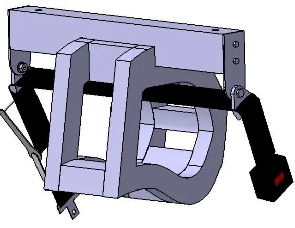
Figure 18. Complete concept CAD model of the CRSIAD...33
Figure 19. MAT_WOOD material model formulation flow chart...38
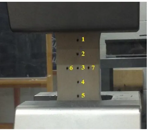
Figure 20. Hand-marked strain gauge dots (1 to 7) for video extensometer capturing...42
xv
Figure 22. Specimen with marked strain gauges (A) and captured strain gauges on the controller (B)...43
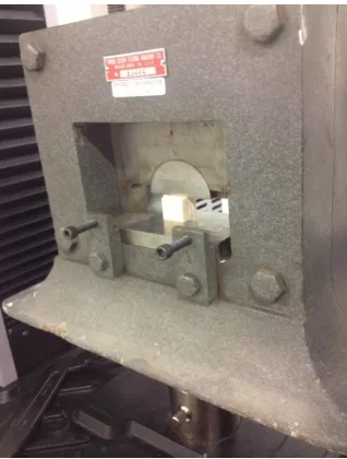
Figure 23. Tensile test setup in parallel to fibre direction with specimen placed in grip crosshead...44
Figure 24. Tensile test setup for the perpendicular to fibre direction configuration...45
Figure 25. The specimen for the compression testing in the parallel direction of the wood fibre placed between the compression plates...46
Figure 26. Test setup for the compression testing in the perpendicular direction to the wood fibre...47
Figure 27. The setup of the specimen on the Tinius Olsen Shear Test Apparatus...48
Figure 28. Test setup for three-point bending test...49
Figure 29. The representative stress versus strain response for the tensile test in the parallel direction of the wood fibre...51
Figure 30. Poisson’s ratio (horizontal strain/vertical strain) versus time...52
Figure 31. The representative stress versus strain response for the tensile test in the perpendicular direction of the wood fibre...53
Figure 32. The representative stress versus strain response for the compression test in the parallel direction of the wood fibre...54
Figure 33. The representative stress versus strain response for the compression test in the perpendicular direction of the wood fibre...55
Figure 34. The representative stress versus strain response for the shear test in the parallel direction of the wood fibre...56
Figure 35. The representative stress versus strain response for the shear test in the perpendicular direction of the wood fibre...57
Figure 36. The load versus crosshead displacement response for the three-point bending testing...58
Figure 37. Specimen for tensile test parallel to fibre direction in FEA geometry (A) compared to lab test specimen (B)...67
Figure 38. Tension parallel to fibre direction load versus displacement comparison...69
Figure 39. Specimen for tensile test perpendicular to fibre direction in FEA geometry (left) compared to lab test specimen (right)...71
xvi
Figure 41. Specimen for compression test parallel to fibre direction in FEA geometry (A)
compared to lab test specimen (B)...74
Figure 42. Compression Parallel to fibre direction load versus displacement comparison...76
Figure 43. Specimen for compression test perpendicular to fibre direction in FEA geometry (A) compared to lab test specimen (B)...78
Figure 44. Compression perpendicular to fibre direction load versus displacement comparison...79
Figure 45. Specimen for shear test parallel to fibre direction in FEA geometry (A) compared to lab test specimen (B)...81
Figure 46. Shear Parallel to fibre direction load versus displacement comparison...82
Figure 47. Specimen for shear test perpendicular to fibre direction in FEA geometry (A) compared to lab test specimen (B)...83
Figure 48. Shear Perpendicular to fibre direction load versus displacement comparison...84
Figure 49. Three-point-bending test setup in LS-PrePost...86
Figure 50. Three-point-bending load versus displacement comparison...87
Figure 51. Device main frame side profile imported into LS-Prepost with 4-line sections...91
Figure 52. Side view of the CRSIAD geometry constructed in LS-PrePost...92
Figure 53. Fully constructed CRSIAD geometry in LS-DYNA ready for simulation...93
Figure 54. Local coordinate system created for the vector of loading direction (positive x as loading direction)...94
Figure 55. Local coordinate system created for the vector of loading direction (positive x as loading direction)...95
Figure 56. Energy balance for forward-facing configuration simulation (implicit approach)...97
Figure 57. Energy balance for forward-facing configuration simulation (explicit approach)...98
Figure 58. Contact interface force summary (Sl 2: Slave side force at Contact Interface 2; Ma 2: Master side force at Contact Interface 2; Sl 1: Slave side force at Contact Interface 1; Ma 1: Master side force at Contact Interface 1)...99
Figure 59. Energy balance for rearward-facing configuration simulation (implicit approach)..101
Figure 60. Contact interface force summary (Sl 2: Slave side force at Contact Interface 2; Ma 2: Master side force at Contact Interface 2; Sl 1: Slave side force at Contact Interface 1; Ma 1: Master side force at Contact Interface 1)...102
xvii
Figure 62. The loading beam assembly design of the CRSIAD...106
Figure 63. Four seatbelt clip and buckle combination A, B, C and D...108
Figure 64. Stitched webbing with selected seatbelt attachments...110
Figure 65. The preparation setup for the CRSIAD before it was loaded onto the CRS...112
Figure 66. Forward-facing Configuration Preliminary Test Setup for the CRSIAD...113
Figure 67. The Rearward-facing Configuration Preliminary Test Setup for the CRSIAD...114
Figure 68. A comparison between the new ratchet (left) and the original ratchet (right) in terms of size and webbing...116
Figure 69. The downsized webbing stuck at the corner of D-ring slot while under tension...117
Figure 70. Webbing in the D-ring with slack (A) and with no slack after silicone stuffed at the slot ends (B)...118
Figure 71. The CRSIAD setup with center-mounted ratchet...119
Figure 72. The steel adjustable clip applied to the ratchet webbing...120
Figure 73. The complete assembly with adjustable clips installed on the ratchet webbing...121
Figure 74. Difference on the lower anchor strap routing location between two CRSs (Graco Comfort Convertible on the left and Eddie Bauer Alpha Elite on the right) pointed with red arrows...122
Figure 75. The section on the CRS in contact (circled red) with the CRS (Eddie Bauer Alpha Elite) as geometry conflicted zone...123
Figure 76. Exact-traced template on the left with conflicted section trimmed out (pointed by red arrow); actual fitment on the CRS on the right to show clearance as a result of the trimming the conflicted section (pointed by red arrow)...124
Figure 77. Modification completed on CATIA to show the added section (pointed by yellow arrow) and trimmed section (pointed by red arrow)...126
Figure 78. Modified geometry of the CRSIAD with its mesh quality...128
Figure 79. Energy balance for forward-facing configuration simulation (implicit approach) with modified geometry...129
Figure 80. Energy balance for rearward-facing configuration simulation (implicit approach) with modified geometry...129
Figure 81. Original device main frame (A) and modified version (B)...131
xviii
Figure 83. Positioning of the ratchet with the aid of Velcro strap...133
Figure 84. Average scores for all questions in the survey sheet...136
Figure 85. The CRSIAD set up in the test vehicle in forward-facing configuration...138
Figure A. Tensile Test Parallel to Surface Specimen...150
Figure B. Tensile Test Perpendicular to Surface Specimen...151
Figure C. Compression Test Parallel to Surface Specimen...152
Figure D. Compression Test Perpendicular to Surface Specimen...153
Figure E. Shear Test Parallel to Surface Specimen...154
Figure F. Shear Test Perpendicular to Surface Specimen...155
Figure G. Three-point-bending Test Specimen...156
Figure H. Failed Specimen in Tensile Parallel Test (left), Perpendicular Test (right)...157
Figure I. Failed Specimen in Compression Parallel Test (left), Perpendicular Test (right)...157
Figure J. Failed Specimen in Shear Parallel Test (left), Perpendicular Test (right)...157
Figure K. Tensile test in parallel direction of the wood fibre...158
Figure L. Tensile test in perpendicular direction of the wood fibre...158
Figure M. Compression test in parallel direction of the wood fibre...159
Figure N. Compression test in perpendicular direction of the wood fibre...159
Figure O. Shear test in parallel direction of the wood fibre...160
Figure P. Shear test in perpendicular direction of the wood fibre...160
Figure Q. Three-point-bending test...161
xix
LIST OF APPENDICES
Appendix A. CRS Measurements Survey...147
Appendix B. Specimen Blueprints...150
Appendix C. Material Testing Raw Data...158
Appendix D. Wood Material Models...162
Appendix E. Material Testing Results...163
xx
LIST OF ABBREVIATIONS
FAAP Fellow in the American Academy of Pediatrics
ASTM American Society for Testing and Materials
CMVSS Canadian Motor Vehicle Safety Standards
CRS Child Restraint System
CRSIAD Child Restraint System Installation Aid Device
FMVSS Federal Motor Vehicle Safety Standards
HIC Head Injury Criteria
xxi
NOMENCLATURE
B, D Softening parameters (parallel and perpendicular)
CI, CII Constants that relate fracture intensity to fracture energy
Cijkl Material stiffness tensor (elastic moduli)
Cij Material stiffness components
c||, c⊥ Hardening-rate parameters (parallel and perpendicular)
d, d||, d⊥, dm Scalar damage parameters (general, parallel, perpendicular,
and max(d||,d⊥))
dmax||, dmax⊥ Maximum damage allowed (parallel and perpendicular)
E11, E22, E33 Normal moduli of an orthotropic material
EL, ET Normal moduli (wood notation)
FM, FS Factors to scale moduli and strengths with temperature
f||, f⊥ Yield surface functions (parallel and perpendicular)
f||*, f⊥* Trial elastic yield surface functions (parallel and perpendicular)
G||, G⊥ Hardening model translational limit functions (parallel and
perpendicular)
Gf ||,Gf⊥ Fracture energies (tension and shear)
Gf I ||, Gf II || Parallel fracture energies (tension and shear)
Gf I⊥, Gf II ⊥ Perpendicular fracture energies (tension and shear)
xxii
G12, G13, G23 Shear moduli of an orthotropic material
GLT, GLR, GTR Shear moduli (wood notation)
I1, I2, I3, I4 Stress invariants of a transversely isotropic material
I1*, I2*, I3*,I4* Trial elastic stress invariants
KI, KII Fracture intensities (tension and shear)
L Element length
MC Moisture content
n||, n⊥ Rate-effect power parameters (parallel and perpendicular)
N||, N⊥ Hardening initiation parameters (parallel and perpendicular)
QT, QC Quality factors (tension/shear and compression)
R Stress enhancement factors (ratio of dynamic to static strength)
Sij Compliance coefficients (reciprocals of elastic moduli)
S||, S⊥ Shear strengths (parallel and perpendicular)
T Temperature
V Impact velocity in Hopkinson pressure bar tests
X, XT, XC Parallel wood strengths (general, tension, and compression)
Y, YT, YC Perpendicular wood strengths (general, tension, and compression)
αij Backstress tensor (and incremental backstress for hardening model
γ, γ||, γ⊥ Viscoplastic interpolation parameters (general, parallel, and
xxiii
εij, Δεij Strain tensor and strain increments
ε11, ε22, ε33, Strain components of an orthotropic material
ε12, ε13, ε23
ε1, ε2, ε3, Strain components (shorthand notation)
ε4, ε5, ε6
εL, εT, εR, Strain components (wood notation)
εLT, εLR, εTR
ΔεL,Δε LR, Δε LT Strain-rate increments parallel to the grain (wood notation)
ΔεT, ΔεR, ΔεTR Strain-rate increments perpendicular to the grain (wood notation)
ε|| ,ε⊥ Scalar effective strain rates (parallel and perpendicular)
Δε||, Δε⊥ Scalar effective strain-rate increments (parallel and
perpendicular)
Δλ||, Δλ⊥ Plasticity consistency parameters (parallel and perpendicular)
Δt Time-step increment
η General rate-effect fluidity parameter
η||, η⊥ Tension/shear rate-effect fluidity parameters (parallel and
perpendicular)
ηc||, ηc⊥ Compression rate-effect fluidity parameters (parallel and
perpendicular)
ρ, ρs Density of wood and of wood solid phase
xxiv
σij, σij, σij,σij, σij Stress tensors (trial elastic, inviscid, inviscid with backstress,
viscid, and viscid with damage)
σ11, σ22, σ33 Stress components of an orthotropic material
σ12, σ13, σ23
σ1, σ2, σ3 Stress components (shorthand notation)
σ4, σ5, σ6
σL, σT, σR Stress components (wood notation)
σLT, σLR, σTR
τ||, τ⊥ Instantaneous strain energy type term for damage accumulation
τ0||, τ0⊥ Initial strain energy type value for damage initiation
νij Poisson’s ratios (indicial notation)
νLT, νLR, νTR Major Poisson’s ratios (wood notation)
Subscripts
L Longitudinal or parallel
T Transverse or perpendicular
R Radial
|| Parallel
1
1 INTRODUCTION
Motor vehicle injuries are leading causes for death among children in North America. Children especially infants, due to their body size and weight, are very vulnerable to impact from the car crash. In 2013, total of 8925 injuries of children under age of 14 were reported in Canada [31], among which 430 were seriously injured.
A Child Restraint System (CRS) can greatly reduce the risk for children’s injury during car accidents. With appropriate use of a CRS, risk for infants (less than one
year old) can be reduced by 71% and 54% for toddlers (aged between one and four) in passenger vehicles [30].
One key component in the vehicle for installing a CRS is LATCH (Lower Anchors and Tethers for Children). LATCH became standard equipment, by law, for all passenger vehicles on September 1st, 2002, which was enforced by NHTSA (Federal Motor Vehicle Safety Standard 225) [1]. Prior to 2002, only car seatbelts were used to restrain Child Restraint Systems (CRSs) in into the car seat, which was proved inadequate to provide the same safety level as a LATCH system. Many vehicle owners who installed CRSs with car seatbelts loosely installed the CRSs so that effective restraining was not achieved [2]. LATCH allows CRS to be tightly and appropriately secured into the car seat so that the CRS will perform at its best capability during a car accident, which drastically reduces the chances of injuries and fatalities of the child occupant.
2
has revealed a disturbing quantity of CRS misuse among 267 participating families; 93% of installations contained at least one critical error [7]. Another similar large scale survey completed in 2005 [8] resulted in 13% of participants not using LATCH. For the 87% who did use LATCH, only 4% of them made no error in the installation.
The statistics shown above have indicated no significant improvement of children’s safety for the last decade mainly due to misuse of LATCH system. With
the existing design of the LATCH system on the passenger vehicles, there is no
other way a CRS can be installed differently in near future. Correspondingly, the need for a supplemental device, to reduce human effort during installation, could
3
2. LITERATURE REVIEW
2.1 LATCH Theory
On the vehicle, lower anchor bars are fitted where cushions meet in the car backseat as shown in Figure 1. The locations of the anchor bars are standardized for all car manufacturers.
Figure 1.Typical LATCH system on passenger vehicle seat [3].
4
rear window (Point 1 in Figure 2). If the CRS is installed on the second-row seat of a minivan, the location will be on the floor behind the seat (Point 2 in Figure 2).
Figure 2. CRS with both top tether and lower anchor webbing [4].
The introduction of LATCH evolved the CRS industry. The main improvement on safety can be described in the following two aspects.
1. Using of the lower anchors instead of seatbelt to restrain the CRS eliminates the need to know how to use the seatbelt or locking clip to install the CRS which had been the core of misuse prior to 2002. The use of LATCH was proved to be an easier method to install the CRS than the use of seatbelt as it provides a tighter fit than the seatbelt itself [5].
2. The introduction of applying a top tether on the CRS effectively reduces forward head excursion of infant during a car accident event. Without a top tether being attached to the CRS, the top portion of CRS will be loose. The slack on the
5
2.2 Statistics Associated with LATCH Misuse
Misuse of a CRS can put infants at increased risk of injury in a car crash. A recent major survey was completed between November 2013 and May 2014 at the Oregon Health and Science University Hospital which has revealed a disturbing quantity of CRS misuse among 267 participating families; 93% of installations have contained at least one critical error [7]. The study was conducted with the purpose of estimating the rate of CRS misuse of newborns upon hospital discharge as well as elucidating risk and protective factors for CRS misuse.
At the Oregon Health and Science University Hospital, The Mother Baby Unit discharges about 2500 newborn babies every year. Selected sampling was done on
daily basis to ensure the data collected was legitimate. The newborns with less than thirty-seven weeks of gestation age, with Neonatal Intensive Care Unit (NICU) stay over four hours and leaving in personal vehicles were chosen for the experiment. Up to four new mother/infant dyads were surveyed everyday between November 2013 and May 2014. Participants' tasks were to simply place their baby in the CRS and install the CRS into the car that they were leaving with. During the installation process, a certified Child Passenger Safety (CPS) Technician observed these activities and recorded all cases of misuse according to the best-practice guidelines of the Safety Kids Worldwide and American Academy of Pediatrics (APP).
6
Most Common Errors in Positioning Infant Percentage (%)
Harness too loose 69
Retainer clip too low 34
Use of after-market product not approved with seat 20
Harness too high 18
Caregiver not knowing how to adjust harness 15
Table 1. Error Percentage for Infant Positioning [7].
Most Common Installation Errors Percentage (%)
CRS installed too loosely 43
Angle of car safety seat incorrect 36
Safety belt used but not locked 23
Incorrect spacing between CRS and vehicle front seat 17
Table 2. Error Percentage for CRS Installation [7].
The results from the experiment noted above showed similarity to an experiment conducted in 2005 by the NHTSA, which was completed over a decade ago at the publishing date of this thesis. Between April and October 2005, NHTSA conducted a survey specifically for the misuse of LATCH [8]. This study was the first large-scaled survey specially designed to study LATCH misuse. They engaged the survey at 66 places including shopping centers, child care facilities, health care centers and recreation facilities in 7 states in the USA. NHTSA focused on whether or not drivers with LATCH-equipped vehicles were using LATCH to secure their CRSs to the vehicles and if the CRSs were properly installed. The make, model and type of CRS installed in each seating position were recorded for each of the vehicles.
7
Our best interest of the survey is the data for the lower anchor misuse. Observations showed that 13% of the CRSs were installed in a seat where lower anchors were not equipped, which is the centre seat of the vehicle backseat. For the remaining 87% who did place the CRS at the right location, 40% of these parents did not use the lower anchors bars at all because they relied using the car seatbelt to restrain the CRS. Even if the remaining 60% of participants used lower anchor to attach the CRSs to the vehicle, a significant amount of misuse was identified.
From the entire survey, 52.2% used lower anchors as the method to secure their
CRSs and protect their children from car accidents. The ones who did not use lower anchors suggested their lack of knowledge is the primary cause. Figure 3 presents
details of the misuse of lower anchors among this survey.
From this chart, the highest percentage of lower anchor misuse appeared to be loose installation. This means the CRS can be moved from side to side for more than one inch after the installation was complete. Loose lower anchor straps will not securely hold the CRS down to the car seat upon an accident, which causes additional slack in the CRS that could lead to increased risk of the occupant's injury and death.
8
The two large-scale surveys mentioned above are ten years apart from each other but results are similarly disturbing. With no significant improvement on CRS misuse over the last ten years, it is vital to find out the leading cause of CRS installation misuse. Although CRSs are made as intuitively as possible with clear instructions attached, parents with newborns still tend to misuse them. The experiment performed in 2009 by Tsai and Perel focused on installation errors among both novice and experienced users [9]. Common mistakes presented in both the novice and experienced groups of participants but the novice group showed more errors than the experienced group. The results were consistent with the
experiment lead by Benjamin Hoffman, MD, FAAP [7], in which lack of knowledge on CRS installation played a big role in CRS misuse. In 2004, Transport Canada conducted an environmental scan of educational initiatives aimed at increasing physicians understanding of CRS, which identified pediatricians as having lack of understanding for the correct seating of CRS in motor vehicles [10].
2.3 Physical Effort That Leads To LATCH Misuse
9
Figure 4. CRS installation for forward-facing configuration by certified CRS installer.
CRS misuse is not only caused by lack of education and understanding but also the physical effort needed from the parents and caregivers who perform the
installation. An important experiment of performing CRS installation was conducted in 2006 to specifically study the physical effort needed to complete the installation [12]. A group of twenty-seven parents were gathered to install a CRS into a mocked-up second row seat of a minivan. These parents did not have prior experience of installing CRSs which represented the majority of the population. Electrogoniometers were fitted on participants' bodies to measure their body joint extension and radial deviation. Additionally, muscle activation was also assessed in the study. Since this experiment emphasized the effort of correct CRS installation, all participants were guided to a successful installation except two.
10
tethering. The peak levels were observed to be over 90% of maximum in 18 of 30 muscles. Figure 6 shows that the shoulders were forced into extreme postures during all 3 tasks, which were installing seat, securing tether and placing child.
Figure 5. Average peak (99th percentile) EMG amplitudes for each muscle and
condition [12].
Figure 6. Peak (99th percentile) of average frequency distribution curves for the
11
Therefore, correct CRS installation was found to be very physically demanding. Maximum effort of some muscles could result in inadequate securing of the CRS into the vehicle. The seat installation typically requires high efforts and awkward postures for tightening the upper and lower LATCH straps. These demanding tasks result in loose installation being a frequent misuse characteristic. Even for large size vehicles, the necessary workspace to for CRS installation is tight and requires the installer to bend down and sit on his/her knees to complete installation.
2.4 Effect of Loose LATCH Installation
The use of LATCH started with a good concept but formed a new direction of misuse [6]. LATCH did not increase the safety for children in car accident due to its unfortunate misuse. The leading cause of CRS misuse is loose installation, which is caused by human error due to both lack of understanding and physical demands for correct installation.
The effect of loose LATCH tethers on CRS during a car accident is important to study to find out the level of safety risk for the occupant. Due to high cost of conducting real experiments involving crash test dummies and experimental crashworthiness facilities, numerical simulation is cost-efficient in analyzing a child sized crash test dummy’s damage under different crash events.
In the numerical study in 2002 [13], simulations were run to investigate head and neck injuries sustained by toddlers due to CRS misuse under frontal and side impact crashes. Finite element dummy models created based on a 3 year-old child called Hybrid III and Q3 were used in this study. Tests were done according to CMVSS 208 and FMVSS213 testing conditions [14].
12
lower portion of CRS is not tightly fastened into the car seat. Simulation predictions illustrating the kinematics of a CRS and 3 year old Q3 dummy for both correct CRS installation and misuse, as presented in Figure 5, has indicated significant difference between the motion of the two different configurations.
Figure 7. Comparison results for correct and loose LATCH installation for
forward collision (left) and side impact (right) scenarios [13].
Acceleration based parameter Head Injury Criterion (HIC) was used to measure head injury risk quantitatively in the crash simulations. In this simulation, HIC15 and HIC36 were used as appropriate measurements to evaluate head injury according to NHTSA [15]. The results have shown an increase in peak resultant head acceleration by about 12% for the frontal crash condition and 15% for the near-side impact condition due to the lower portion of CRS not being tied down to the car seat properly (slack in seatbelt). Forward head excursion during the crash event was increased by approximately 20% for the Hybrid III dummy due to the presence of slack in the lower portion of CRS.
13
children. For both frontal and near-side impact conditions, neck forces were increased by 5-10% for the Hybrid III dummy and 15-25% for the Q3 dummy due to the slack in lower portion of CRS. Additionally, an increase of approximately 15% of resultant upper neck forces was observed for the same slack in the system.
The increased head acceleration may not lead to death but certainly increases the probability for both brain and neck injuries for the infants. Increased head excursion will raise the potential for contact with vehicle interior parts especially in side-impact cases.
2.5 Review of Loose CRS Installation Errors
14
Figure 8. Hierarchical Task Analysis of proper CRS installation [9].
An experimental focused study on CRS installation errors was conducted in 2009 and has shown 85% of loose installation on convertible CRSs [9]. Tightening of the CRS into the car seat was found to be the most challenging task in the installation process. The main issues of CRS installation have been identified as the following:
1. Space - Vehicle interior space is a key limitation for CRS installation. After placing a CRS onto the car seat, the room for the installer to work with the CRS is very limited. Reaching the LATCH strap and tighten it will require some extreme
15
2. Instructions - Many parents have been found to become confused between using car seatbelt and LATCH system to fasten a CRS [11]. Some users found the instructions difficult to understand so that they followed wrong instruction order to perform the CRS installation. Some parents complained about the lack of warning signs on the CRS for tightening the system.
3. Adding weight - Most parents did not understand how to get CRS installed in an appropriately tight manner. Some parents ignored the step of placing knees onto the CRS when tightening the LATCH strap because they were not aware that adding
weight is the only way to achieve an appropriately tight installation [1]. Some parents were unable to complete the step due to space limitation. For
16
3 FOCUS OF RESEARCH
After a thorough investigation on the literature regarding child safety in passenger vehicles, it was evident that misuse of CRS is an alarming issue that needs to be addressed. Specific to loose LATCH tether connections, CRS misuse is a result of both human error and inability to provide suitable preloads to the tethers.
Correct installation of LATCH tethers is vital for a CRS to perform as designed. However, from numerous major surveys conducted in North America, the majority
of parents are unable to perform correct installation of CRS with the LATCH system. Lack of experience is the first factor that contributes to human error [1]. Most installers of CRSs are new parents who have never previously performed a CRS installation. They were confused by the installation manual and unsure how the LATCH system should be correctly installed. They easily overlook the required tightness of LATCH straps for the CRS to work safely in the vehicle [5].
Tightening LATCH straps in the vehicle is a challenging task due to space limitations and the required physical effort [12]. With the existing design of LATCH system on automobiles, there is no other way CRSs can be installed differently. Correspondingly, the need for a supplemental device, to reduce human effort during installation, could play a significant role in reducing the CRSs installation errors and thus mitigate misuse and increase child safety in vehicles.
In this research, computer aided engineering (CAE), manufacturing, and physical testing was conducted to develop a Child Restraint System Installation Aid Device (CRSIAD) for the purpose of mitigating CRS installation errors. The main focus of this research can be summarized in the following points:
1. To study and build a material model that is suitable to be used for
17
characterization is needed to assess the performance of lightweight wood materials, for data needed in the generation of an anisotropic material model. The developed material model will be validated to the experimental data using a suitable quantitative means of model validation.
2. To design a CRSIAD mechanism that will preload the CRS into the car seat, thus reducing the physical effort for installing the CRS and potentially mitigating misuse.
3. To construct the CRSIAD geometry based on given CRS geometry and spatial constraints developed from the surveying of existing CRS
products among major suppliers in the market. Following the creation of such CAD data a full FEA model of the CRSIAD will be developed and also incorporate the material model developed in item (1) above. Simulation of the CRS installation loading conditions for both forward-facing and rearward-forward-facing configurations will also be considered. The appropriate geometry design iterations will be performed, using FEA, until the loading stress level is within the yield limit of the material and a lightweight design is achieved.
4. To fabricate the CRSIAD according to the CAE efforts identified in item (3) above. Following the manufacturing, the device will be tested in a number of popular production vehicles. Design iterations will be completed to ensure appropriate performance and ease of use.
18
4. CRSIAD GEOMETRY DESIGN
4.1 In-car Concept Model Development
To initiate the design for the CRSIAD, it was helpful to start with developing a mock-up system that can achieve preloading of the CRS into a vehicle. The goal was to build such a system with attainable parts from hardware stores.
4.1.1 Loading Mechanism
A readily available loading device is necessary for the system to apply load on the CRS. A suitable product for load application was discovered to be a car scissor jack after exhaustive examination of viable alternatives as shown in Figure 10 in Section 4.2.1. It is designed to support and raise in a quasi-static fashion approximately one-quarter of the weight of a car so that the loading capacity was assumed to be more than sufficient.
4.1.2 Restraining Components
In order to operate in a manner necessary to load the CRS into the vehicle seat,
the top end of the scissor jack needed to be constrained so the loading device would apply a counter-force towards the CRS. The seatbelt on the vehicle was found to be
the ideal component to restrain the top of the scissor jack. However, the lap belt and shoulder belt counter-react with each other. For example, when the lap belt is being pulled and extended, the shoulder belt retracts because they are on the same belt loop. This feature is by design and allows passengers to adjust the belt according to their body sizes. Therefore, this flexibility will not suitably restrain the top of the jack in a method needed to load the CRS into the vehicle seat.
19
market as people who install CRS with car seatbelts are encouraged to use the clip for restraining purposes [3]. Utilizing the H-clip between the lap belt and shoulder belt together results in no counter movement between the two as illustrated in Figure 9. Therefore with the addition of an H-clip, even when the jack was pushing up against the lap belt, the entire seatbelt system remained stationary so that the top of the jack was kinematically constrained.
A B
Figure 9. Seatbelt with adjustable webbing (A) and with H-clip (B).
4.2 In-car Concept Model Testing
A feasible concept model was developed with trial-and-error approach for initiating further design process.
4.2.1 Test Setup
20
With the lap belt restraining the top of the scissor jack, the scissor jack was expected to push the CRS downwards while being actuated.
Figure 10. Simple scissor jack concept device installed on a CRS.
4.2.2 Test Results
The pilot testing was discovered to be a success for the purpose of preloading. The system was able to preload the CRS into the car seat deep enough so that lower anchor straps could be tightened by hand to complete the CRS installation process. However, there were some areas for improvement that were valuable for further design consideration of the CRSIAD.
The actuation of the scissor jack was very slow which may potentially frustrate the installer as a result of the significant time needed to suitably load the system.
21
Seating of the scissor jack on the CRS was not ideal as a result of surface contour differences between the bottom side of the jack, which exhibits a flat surface, and the seating surface of CRS, which has a curved contour. When the jack was being actuated the alignment of the system was disturbed and was not necessarily ideal. The moving direction of the jack and the supporting direction of the lap belt are not parallel so there was potential for them to separate during the operation.
4.2.3 Recommendations for Designing CRSIAD
The scissor jack configuration served its purpose as a design concept but also
exposed issues that need to be resolved during the design phase. The identified issues are listed and discussed as following.
The CRSIAD would need to be operated within a reasonably short time to achieve the preloading process. The issue of slow speed would not affect mechanical performance but rather the user’s patience. It is important to maintain enthusiasm of using the CRSIAD so that people who have used it would likely use it again or introduce it to others.
The device would need to be properly seated and aligned in a CRS throughout the entire loading process. The mismatched shape of the scissor jack created issues of alignment which made the preloading process inefficient. This will require the bottom surface of the CRSIAD to appropriately match the contour of the seating surface of CRS. With properly-matched contacting surfaces between the CRSIAD and CRS, maximum efficiency of loading can be achieved. Potential contact with other parts of the CRS should be avoided. Preloading should be concentrated only on the proper contact area to achieve good efficiency. Contact with the side frame of the CRS during operation could also cause misalignment.
22
acting on the CRS will be directed to a most effective angle. In this case, the loading direction should directly point to the lower anchors in the car seat, which would effectively create slack in the lower anchor webbing on CRS so that it could be tightened by hand to complete the installation process.
The device should be easy to operate. Using the scissor jack setup was tricky due to the issues above, which could cause confusion for the users. The main purpose of designing CRSIAD is to mitigate misuse. Any confusion of using the CRSIAD could cause new misuse that would defeat the purpose of this project. The
CRSIAD should be designed to be used in a reasonably self-explanatory way and also be user-friendly.
4.3 Geometric Constraints
Before designing the geometry of the CRSIAD, it was important to understand the volume that the device could be used within. The geometry of the device would need to correlate with the interior of the vehicle as well as the geometry of the CRS.
4.3.1 Defining the Geometric Constraints For Key Dimensions
23
The inner width of the seating area (the dimension "A" in Figure 11) is critical because the CRSIAD will be located at this region. The width of the CRSIAD must not be narrower than the inner width of a CRS. The minimum inner width of CRS was to be measured and recorded on the survey.
Figure 11. Model name Baby Trend Flex Loc Infant Seat with inner width (the red
dimension "A") and outer width (the blue dimension "B").
24
The outer width of the CRS (the dimension "B" in Figure 11) was important for the design of the width for the CRSIAD. The width of the CRSIAD must be greater than the width of the CRS in order for the CRSIAD to be appropriately anchored to the vehicle without potential contact with the CRS. The outer width of the CRS was the distance measured from widest points of the CRS including accessories such as cup holders and armrests. The greatest surveyed value for outer width of CRS was measured to be 510.54 mm as shown in Table 18 in Section Appendix A. Minimum or average values of this dimension are not important since the width of the CRSIAD only needs to overcome the largest measured width of the CRS among all
surveyed CRSs.
With the width limits obtained, it was necessary to determine the limitations on the vertical plane (CRS side view plane as shown in figure 12). Due to the variations among the CRS models in the market, a series of critical locations, which may affect the geometry design of the CRSIAD as well as its functionality, had to be defined.
25
Figure 12. Side View of CRS with Local Coordinate System for Defining Critical Points.
26
4.3.2 Measurement Process
A measuring tape was used to measure the widths of all the surveyed CRSs. Five measurements were done on each dimension and average value was recorded.
The method of identifying the origin, Point O, was mentioned previously in section 4.3.1. Inner and Outer widths from Figure 12 were measured easily with measuring tape. Points 1 and 2 were measured based on the origin (Point O) in the x/y coordinate axes. With the coordinates of Points 1 and 2 obtained, a typical CRS side design envelop was established as shown as the green zone in Figure 13 (A).
Some surveyed CRSs had accessories on the sides such as an armrest or cup
holder. In such cases, measurement was simplified shown in Figure 13 (B). Only one point (Point A) was needed to replace both Points 1 and 2 from Figure 14 because Point A is both the highest point of lower wing (due to added armrest) and the left most point of side wing. All recorded coordinates are available in Table 18 in Appendix A.
A B
Figure 13. Sample CRSs (A: Graco Comfort Convertible with no accessory; B: Eddie Bauer
27
4.4 Concept Model Geometry Generation
The previously developed scissor jack system was used as a starting concept for creating the geometry of the CRSIAD. Although only a mock-up, this system was helpful in identifying issues and constraints for further developing the shape of the CRSIAD. Therefore, the design process of CRSIAD commenced with resolving problems from Section 4.2.4 combined with the geometrical constraints from the developed space envelop presented Section 4.3.2.
4.4.1 Main Frame Shaping
The contact section at the base and back of the CRSIAD needed to match closely with existing CRS geometry to avoid any misalignment or load concentration issues.
Existing CAD data of CRS geometry, namely a Graco Convertible CRS was used to create the bottom section of the CRSIAD so that the bottom profile was appropriately aligned. The seating sections for the majority of CRSs in the market were found to be very similar in shape. This was advantageous to the design of the CRSIAD geometry as the CRSIAD would have to fit universally to all CRSs.
28
Figure 14. The CRSIAD representative entity A with closely matched bottom
profile (red mark) to the given CRS geometry B.
The matched contact surfacing allows the load to be distributed evenly which ensures stability during the preloading process. With the bottom profile of the CRSIAD aligning to the CRS, the potential for the CRSIAD to damage fabric of CRS during the operation was also minimized.
4.4.2 Main Loading Mechanism
The preloading time of the CRSIAD should be controlled within ten seconds for the convenience of the users. Therefore, a fast and convenient mechanism should be adapted in the design to ensure enthusiasm of the installers for using the CRSIAD.
29
the CRSIAD requires a motor with sufficient torque to support the loading weight equivalent to a human body. Such a motor is typically heavy and rated at higher voltage than 12 Volts that a normal vehicle can supply. Searching for a suitable pneumatic device was also unsuccessful due to size and packaging limitations during the time of searching. A ratchet strap assembly is robust, compact and readily available in the stores. When properly used, the ratchet strap can appropriately preload with minimal rotation, motion and effort. Car seatbelt webbing was first chosen for the ratchet strap assembly due to its safe loading capacity for passengers. A 1500 lb ratchet was then selected to match the width of
the seatbelt webbing which is 50.8 mm.
At this point, the geometric constraints developed previously in Section 4.3.2 must be used for developing the top CRSIAD geometry. The loading points of the ratchet webbing must be located within the "design zone" in Figure 15 to avoid any contact between itself and the CRS body.
4.4.3 Loading Structure
30
Figure 15. Original design of loading beam of the CRSIAD (black part is a
dummy strap that runs across).
This design concept was reasonable and a curved surface ensures even distribution of the load from the webbing. However, the surface contact area between the webbing and beam was predicted to be quite significant in this case. The strap would move in one direction when it was being operated by the ratchet, which would create lateral frictional load on the beam surface. The large amount of friction would compromise stability of the system and potentially tilt the entire system to one side. Such issue needed to be addressed and therefore the beam needed to have as little amount of contact area with the strap as possible while maintaining functionality of the webbing.
Seatbelt D-rings from production vehicles were used for minimizing belt friction in the seatbelt system. They are ready-made and tested for production vehicles with minimum friction and safe for loading. They were to be mounted on each end of the
31
Figure 16. Loading beam design with attached D-rings.
4.4.4 The CRSIAD Restraint System
There is one missing component in the system that plays an important role for the CRSIAD, namely, the restraint system. The foundation of the CRSIAD structure had been established, which consist of a main CRSIAD frame, loading beam and ratchet strap assembly. However, this concept would not work without having the ratchet strap ends being attached to fixed points in order for the system to operate.
From the scissor jack concept model (Section 4.2.3), it was concluded that the loading direction of the CRSIAD should ideally be pointing towards the lower anchor points which will coincide with the loading direction of the LATCH webbing. Existing car seatbelt system was found to be useful during the scissor jack concept testing and would be feasible for CRSIAD.
32
comfort. Due to the requirement that both ends need to be fixed for the purpose of restraint, the flexible end (either male or female) would need to be a fixed end. As discussed in Section 4.1.4, an H-clip can be implemented to the extendable end to prevent relative motion between belts.
With all components mentioned above combined, a concept restraint system was designed to serve the loading structure to the CRSIAD as shown in Figure 17. A ratchet is attached to the left side of loading beam with the end attachment being male seatbelt clip; the Female buckle is attached to the webbing located on the right
side. Although the design seemed to be feasible, each component needed to be carefully considered and engineered to meet all design specifications. The loading
beam would need to be designed to a specific width as mentioned in Section 4.4.3 and built from a suitable material. D-rings and ratchet straps are off-the-shelf products but needed to be carefully selected. Sizing of the webbing and loading capacity had to be considered for the specific CRSIAD application. All the seatbelt clips and buckles needed to fit in majority of production vehicles in the market.
33
4.4.5 Complete Assembly Geometry
Combing the design of the above three components, a concept restraint system, presented in Figure 18, was developed to serve as the loading structure of the CRSIAD.
34
5. MATERIAL TESTING
5.1 Material Introduction
Several major factors were considered when picking the material for the CRSIAD with a sufficient strength to weight level being the top priority. The CRSIAD was expected to sustain loads equivalent to the weight of a human body because the preloading process of CRSIAD was to replace the weight of the
installer. In addition, a lightweight material is preferred due to the need for users to handle such a device often. The material also needed to be relatively rigid because
any flex in the system reduce the efficiency of preloading.
Some feasible and commonly used materials were assessed as candidates shown in Table 2 below.
Density (kg/m3) Elastic Modulus (GPa)
Yield Strength
(MPa)
Stainless Steel 7750 207 520
Aluminum 2768 73 400
Plywood (Tested) 677 9.8 17.6
ABS Plastic 1000 2.3 N/A
Pine Wood 510 9 15.8
Table 3. Comparison of commonly used materials [18].
35
greater than wood. Market pricing of aluminum sheets is also more than twice as much as wood [19]. ABS plastic is lightweight but low elastic modulus value indicates excessive flexibility in the material. As previously mentioned, rigidity is required for CRSIAD to efficiently preload CRS and flex would become a problem. On top of that, ABS plastic is complicated to work with during manufacturing phase.
Plywood is made by laminating wood in thin layers (3mm each ply), which achieves high strength with light weight compared to metal materials [17]. It was
chosen to be the main material to construct the frame of the CRSIAD. As an example, in ASTM Standard D143 - 94 [20], pine wood presents good strength,
weight and hardness. Although yield strength is significantly lower than metal materials in Table 2, it was considered as good candidate for such light loading application.
A suitable material model is vital for performing FEA analysis for the CRSIAD. Plywood is an upgraded version of conventional sheet wood and is widely used in household and construction applications. It presents good strength, weight, hardness and low cost. Compared to conventional wood sheets, its strength is consistent across all directions of the panel. Its multiple (odd number) plies prevent warping and provide improved rigidity compared to other conventional wood sheets [21].
Therefore, plywood was chosen over pine wood due to all its advantages. The material properties were tested in the lab and carefully examined during simulation phase. The material model was also verified with simulation and validated with findings from real testing.
5.1.1 Background
36
an anisotropic material model was used in modeling this material plywood and its mechanical material behaviour under loading. Due to the nature of the problem to be studied, LS-DYNA was selected as the finite element solver for CAE studies. A material model applicable to wood, namely, *MAT_143 (MAT_WOOD), was chosen to simulate the plywood for its ability to model orthotropic wood materials. This model is also applicable for all varieties of wood when appropriate material parameters are selected [22].
5.1.2 Material Model Theory
MAT_WOOD consists of five main sections, namely stiffness, strength, hardening, damage and rate effect, which contain key parameters and are listed below in the complete material model list.
As wood is an orthotropic material, elastic modulus may vary in different wood orientations so and correspondingly this model contains four elastic modulii to describe the elastic material behaviors. Therefore, the stiffness section of the material model contains the following four parameters: EL (Parallel Elastic Modulus), ET (Perpendicular Elastic Modulus), GLT (Parallel Shear Modulus) and
GLR (Perpendicular Shear Modulus). These parameters were determined directly
from experimental results from each test event.
37
parameters: N|| (Parallel Hardening Initiation Parameter), N⊥(Perpendicular
Hardening Initiation Parameter), c|| (Parallel Hardening Rate) and c⊥(Perpendicular
Hardening Rate). These hardening parameters were derived from the nonlinear portion of compressive stress/strain material responses measured in both parallel and perpendicular directions to the wood fibre.
The material damage describes the characteristics of plastic deformation after the ultimate strength, which in the loading curve starts from ultimate stress to failure point. The parameters in this module, B (Parallel Softening Parameter) and D
(Perpendicular Softening Parameter), are only available for tensile and shear test
conditions.
Although the material model incorporates the possibility of involving material rate effect this aspect was not incorporated into the specific application here as the CRSIAD will not to be subjected to any form of high rate loading. Therefore, all rate effect parameters (η) were set to zero.
In addition to the five sections of the material model MAT_WOOD, wood orientation is required to be defined for each test simulation event. Each test specimen is different in wood orientation as it could be either parallel or perpendicular to fibre direction. MAT_WOOD (MAT 143) is specially designed to simulate orthotropic wood material so that such option is available. The material axes option (AOPT) enables orientation definition ability through a locally defined coordinate system to specify vectors for directions parallel and perpendicular to the wood fibre.
38

![Figure 19. MAT_WOOD material model formulation flow chart [22].](https://thumb-us.123doks.com/thumbv2/123dok_us/1382647.1170933/63.612.117.543.80.640/figure-mat-wood-material-model-formulation-flow-chart.webp)