18th International Conference on Structural Mechanics in Reactor Technology (SMiRT 18) Beijing, China, August 7-12, 2005 SMiRT18- K09-5
EVALUATION OF IMPACT OF REPLACEMENT STEAM GENERATOR
LOAD PATH ON EXISTING PLANT SPECTRA
Sohrab Esfandiari
ENOVA Engineering Services
39 Quail Court, Suite 100
Walnut Creek, CA 94596
Phone: (925) 947-6880
Fax: (925) 947-6881
E-mail: [email protected]
Robert P. Kennedy
RPK Structural Mechanics Consulting
28625 Mountain Meadow Road
Escondido, California 92026
Phone: (760) 751-3510
Fax: (760) 751-3537
E-mail:
[email protected]
ABSTRACT
Many commercial nuclear plants are currently undertaking Steam Generator, Reactor Head, Pressurizer, or Turbine Rotor replacement. Replacement of such heavy equipment requires determination of the most effective load path giving consideration to various parameters such as access, cost, and ease of maneuverability, ALARA, and structural capacity of the supporting structures. In general, because of the replacement of such equipment, the unit that is being worked on will be off-line, as such seismic loads need not be considered during the interim. However, if the load path is over common areas of the plant, where there is a desire to keep the unaffected unit(s) operational, then seismic loads become an added parameter that must be considered in design. In addition to determination of structural capacity of supporting structure along the load path subject to the moving load and associated seismic loads, the impact of such a high mass on existing plant spectra must also be evaluated.
In a recent project for a commercial nuclear plant undertaking steam generator replacement, this issue had to be considered. The equipment hatch for movement of the replacement steam generators into the Containment buildings for this plant is such that the traveled load path is in the Auxiliary Building, which is a common building between the two units. As such, in addition to evaluation of the affected load path for dead, live and associated seismic loads, the impact of this added moving mass on nearby plant spectra had to be evaluated. In particular along the vertical direction, because of vertical floor flexibility, the added mass is a significant change compared to existing sub-floor mass, which would ordinarily alter the dynamic characteristics of the floor structural system. However, by allowing for flexibility associated with the tires and the hydraulic support mechanism of the transporter carrying this high mass, it was shown that the added mass is effectively decoupled from the floor and thus has no impact on existing plant spectra. This paper presents the results of evaluation of the impact of the added mass associated with the steam generator load path on existing plant spectra for a commercial nuclear plant.
Keywords: Steam Generator Replacement, SGRP, Load path, Coupling, Resonance, Floor Response Spectra (FRS), heavy loads, Transporter, De-tuning.
INTRODUCTION
Movement of the Replacement Steam Generator (RSG) into the containment building of a commercial nuclear plant required a load path over the roof of the Auxiliary Building through the equipment hatch. Since the Auxiliary Building is a common structure supporting both units, it remains operational whilst one unit is shut down during the SGRP project. As such, the following issues had to be evaluated:
• Impact on global dynamic response of Aux. Building • Impact on local dynamic response of Aux. Building • Stability of the RSG on transporter along the load path
The first issue concerns ensuring that the affected floor(s) along the load path are capable of handling the additional live load and seismic loads associated with movement of the RSG along the desired load path. The second and the third issues deal with evaluation of the impact of addition of such heavy mass on both global and local dynamic response of the structure. The global response is the response of the structure as a whole. The local response is referred to as dynamic response of sub-floors which may have exhibited amplified spectra associated with local vertical floor flexibility. The last issue deals with stability considerations of the RSG on top of the Transporter whilst being moved inside the Auxiliary Building. This stability consideration deals with evaluation of sliding and rocking response of the combined RSG/Transporter under the inertia loads imposed by the plant design basis seismic event.
The focus of this paper is on evaluation of impact of this added “temporary” mass on both the global and the local dynamic response of the structure that must remain operational during such load movement subject to plant design basis seismic event.
IMPACT ON DYNAMIC RESPONSE OF THE STRUCTURE
When impact of an added mass on existing plant spectra is assessed, often this mass is added to the existing mass assuming a rigid connection. This approach was initially adopted for this evaluation. The RSG and the Transporter have a combined weight of 938 Kips. In order to determine the impact of this added mass on dynamic response of the structure, both globally and locally, this added mass must be compared to the existing mass at the elevation of interest to determine percent change in total mass. Since the natural frequency of the structure is inversely proportional to the ratio of the square root of the new mass versus existing mass, this will give an indication of change in frequencies of interest which in turn can be determined if it will have an effect on structure response spectra.
Based on review of dynamic modeling of the structure, it was determined that the weight used in the dynamic stick model of the Auxiliary Building at the floor elevation of interest where the RSG needed to be moved was 76,940 Kips. The addition of 938 Kips associated with the RSG and the Transporter represents an increase of 1.2% of mass at this elevation. Thus, the frequency of the Aux. Building will be reduced by 1/(1.012)0.5 = 0.994. This means the natural frequency will be reduced by 0.6%, which was considered negligible and well within the broadening criteria used for generation of broadened floor spectra. Therefore it was concluded that, the addition of RSG weight had negligible impact on global dynamic response of the Aux. Building.
Locally, only vertical response of floors in the load path is of interest. For the floors along the load path, original analyses of the structure, accounted for local vertical flexibility issues meaning that vertically some of the floors had their fundamental frequency below 33 Hz. (rigid cut-off range). As such, effects of amplification of floor spectra associated with vertical floor flexibility was considered in design, and the vertical floor spectra typically have a peak associated with fundamental local vertical frequencies of the various sub-floor structural systems. Thus, it is expected that due to significantly reduced floor weight associated with individual sub-floor areas (between supporting walls or columns) versus the entire weight at this elevation used in the global model, that the addition of a 938 Kip weight would affect the local vertical response of the floors along this load path. To study the extend of the impact, the local floors along the RSG load path were modeled and dynamic analyses were performed using SAP 2000 (Ref. 2) with the RSG in 4 different and critical locations along the load path. Indeed detailed analysis of the individual floors along the load path subject to the added RSG mass resulted in floor dynamic response and associated spectra which were significantly altered by presence of this moving mass. Table 1 provides a summary of the frequencies of various parts of the floor along the load path without RSG and with RSG in various locations.
postulated to be in position SG1 in close vicinity of Slab location 4, the frequency was reduced to 18.6 Hz., nearly a 40% drop.
Table 1: Summary of Floor Fundamental Frequencies without RSG and with RSG rigidly
attached
Corresponding Freq. (with RSG Mass)
Description No SG SG1 SG2 SG3 SG4
Location 1, 1st mode 19.3 19.3 19.3 19.3 16.2
Location 1, 2nd mode 23.5 23.5 23.5 23.4 20.4
Location 2, 1st mode 28.2 28.2 28.2 28.2 28.1
Location 3, 1st mode 28.8 28.8 28.7 28.8 28.8
Location 4, 1st mode 31.0 18.6 30.4 31.0 31.0
Location 5, 1st mode 33.4 33.4 29.9 21.6 22.0
Location 6, 1st mode 35.3 35.3 35.3 35.3 35.3
Location 7, 1st mode 36.8 36.8 36.2 36.9 36.9
Location 8, 1st mode 37.2 37.2 35.1 37.3 35.8
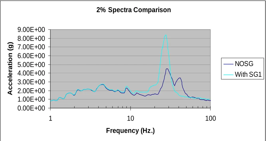
Similarly Figure 1 shows the floor spectra generated allowing for the added mass of the RSG versus the spectra without RSG mass at the same locations:
2% Spectra Comparison
0.00E+00
1.00E+00
2.00E+00
3.00E+00
4.00E+00
5.00E+00
6.00E+00
7.00E+00
8.00E+00
9.00E+00
1
10
100
Frequency (Hz.)
A
c
c
e
le
ra
ti
o
n
(g
)
NOSG
With SG1
Figure 1: Spectra Comparison at Location 1 without RSG and with RSG rigidly attached
As seen from this Figure, it is seen that the addition of this relatively high mass results in a frequency shift to the softer side as well as an increase in spectral amplitude. Such a change can have an adverse impact on qualification of plant equipment subject to this spectrum.
DE-TUNNING OF RSG FROM THE DYNAMIC RESPONSE OF FLOOR
Another solution to this problem, was to dynamically de-tune the RSG from the floors. Examination of the fundamental frequencies of the affected floors showed that the lowest frequency within the load path region was 19.3 Hz. (see Table 1). This is a relatively high frequency floor, and in today’s modern seismic criteria, probably would not be even considered a flexible floor. It was determined that if local flexibilities could be introduced into the support structure of the RSG and the Transporter, it would effectively de-tune it from the floor dynamically, and thus would eliminate the impact of the added mass. Closer examination of the Transporter revealed that significant local flexibilities are actually present in the vertical direction of the Transporter (see Figure 2 for typical Transporter configuration carrying an RSG). Two key contributors to the local flexibility include the flexibility introduced by the tires as well as those introduced by the hydraulic shock absorbers of the transporter. Not knowing the exact details of such flexibilities, it was decided to study the onset of Transporter vertical stiffness which would begin to affect the floor spectra. To study this, the RSG/Transporter was modeled as a series of single degree oscillators carrying the 938 Kips over the footprint of the Transporter with varying oscillator frequencies. Initial evaluation of the RSG and Transporter allowing for flexibility contribution of the tires alone resulted in estimation of oscillator frequency of 1.9 Hz. which is significantly below the first mode of the affected floor at 19.3 Hz, thus achieving the desired de-tuning without contribution from flexibility of the hydraulic system of the Transporter. This analysis case was designated as SG1K1, meaning RSG located at location 1 and with vertical oscillator stiffness K1.
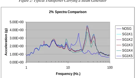
Subsequent analyses were performed by arbitrarily increasing the oscillator frequency progressively to 2.7 Hz., 5.35 Hz., 10.7 Hz., and 21.4 Hz. These analyses cases were designated as SG1K2, SG1K3, SG1K4, and SG1K5 respectively. Table 2 shows the peak acceleration response of the floor at the node where floor spectra was generated closest to RSG in Location 1.
Table 2: Peak Acceleration Response in Slab Location 1
Peak Acceleration Response (g)
Location
NOSG SG1
K1
SG1 K2
SG1 K3
SG1 K4
SG1 K5
Location 1 – At Containment Hatch 1.03 1.03 1.02 1.02 0.99 0.90
Location 1 – Middle of Western Portion
0.80 0.80 0.80 0.76 0.73 0.60
Location 1 – Middle of Containment Arc Portion of Slab
0.84 0.84 0.84 0.84 0.84 0.81
Location 1 – Middle of NE Portion 0.94 0.94 0.94 0.94 0.96 0.99
As seen from this Table, for oscillator frequency up to K4 (10.7 Hz.), the RSG and the Transporter are practically de-tuned from dynamic response of the floor. Figure 3 shows the response spectrum plot for the node that plant spectra were generated and closest to location of RSG in the region of the load path with lowest vertical frequency (19.3 Hz.). As seen from this plot, response spectra are hardly affected until we get to the scenario of SG1K5 meaning an oscillator frequency of 21.4 Hz. These results are as expected, confirming that for the Transporter and RSG vertical frequency in the range of 1.9 Hz. (K1) to 10.7 Hz. (K4), the RSG is practically de-tuned from the floor thus having no impact on the floor spectra.
Figure 2: Typical Transporter Carrying a Steam Generator
2% Spectra Comparison
0.00E+00
1.00E+00
2.00E+00
3.00E+00
4.00E+00
5.00E+00
1
10
100
Frequency (Hz.)
A
c
c
e
le
ra
ti
o
n
(g
)
NOSG
SG1K1
SG1K2
SG1K3
SG1K4
SG1K5
CONCLUSIONS
Based on the results of these analyses, the following were concluded:
1. The addition of the RSG and Transporter mass had no impact on global dynamic response of the Auxiliary Building
2. Because of vertical floor flexibility considerations, the addition of this mass does impact the local vertical response of these floors if no consideration is given to the supporting flexibility introduced by the Transporter tires and hydraulic mechanism
3. By introducing the vertical flexibility of the Transporter, it was demonstrated that the addition of the RSG mass is effectively de-tuned from the local response of the affected floors up to frequency of 10.7 Hz. (vs. floor frequency of 19.3 Hz.). As such, there is no impact on floor spectra.
4. A requirement is placed for the supplier of the Transporter to ensure that sufficient vertical flexibility is in place that will result in vertical frequency within the prescribed range.
PRACTICAL APPLICATIONS
Too often the effects of addition of temporary or permanent mass to the dynamic response of floors in nuclear plants are evaluated giving consideration to mass effects only, assuming rigid attachment to the supporting structure. If the mass addition is heavy, then such evaluation will show that plant spectra are affected. By giving proper consideration to the supporting stiffness of the structure that introduces this mass, one might be able to de-tune the dynamic response of this secondary system from the floor thus eliminating potential impact on floor response spectra. An added advantage is reduced seismic loads for evaluation of the secondary structure itself as well as reduced reaction loads onto the supporting floor.
REFERENCES
[1] – Standard Review Plan, Section 3.7.2, Rev. 2.