ABSTRACT
LUO, HUAN. Efficient Traffic Engineering With Close-to-Optimal Performance. (Under the direction of Dr. Khaled Harfoush.)
Internet traffic has been growing steadily. Some study has shown that the traffic volume was dou-bling every 100 days. While ISPs can add more devices to accommodate more traffic, what’s more important is to manage the traffic in an efficient way so that the same investment can maintain the same level of quality of service while carrying more traffic.
An important objective of traffic engineering (TE) is to balance the traffic to reduce congestion in the network, which can be measured by the maximum link utilization(MLU). Thus a main purpose of traffic engineering is to minimize the MLU. The optimization problem can be formulated as a linear programming problem(LP) and solved in polynomial time. But several challenges exist with the linear programming approach: (1). It’s time consuming to solve it. Depending on the problem size and the hardware platform, the LP problem may take hours to solve; (2). It needs a complete traffic matrix as an input, which is resource consuming to collect; (3) It needs global network status; (4). It has to be performed in a centralized way. These problems make it impractical to deploy LP solutions in real networks.
In this dissertation, we propose a new on-line traffic engineering scheme, TEA, for the MPLS frame-work. TEA targets at minimizing maximum link utilization(MLU) and adapting to traffic dynamics. To make it more efficient, we propose an algorithm to infer unknown link state to avoid global network probing and a scheme (named RLS) to select the largest flows in a network to avoid reporting.
TEA adapts to abrupt changes in the network traffic load by efficiently balancing the load on network links. As opposed to existing Traffic Engineering (TE) techniques, TEA’s reaction to changing traffic loads only disrupts (reroutes) the minimal set of flows in order to bring the network load to a balance and converges in a small number of steps to a close-to- optimal traffic distribution on the network links. Experimental results, on both synthetic and real topologies, reveal that TEA is responsive to traffic surges, results in an optimal distribution of the network traffic on most of the investigated topologies, while rerouting less than 5% of the network flows.
management. Our method can identify the top flows efficiently using one snapshot of SNMP link data without measuring the whole traffic matrix. It combines existing linear programming approach with SNMP link data. We test the method using real topologies. The results show that RLS can accurately identify most of the largest flows over all topologies.
In this dissertation, we describe each component. (1). we describe the main TEA approach, which includes a novel traffic allocation algorithm (named BALANCE) to distribute traffic to a given set of paths. BALANCE can distribute traffic to minimize the MLU for each ingress-egress(IE) pair; It’s executed by each ingress node in a distributed way; (2). We describe the link utilization inference algorithm which can guess the LU of non-bottleneck links using information from bottlenecks; (3)We describe RLS, which identifies the largest flows in a network.
c
Copyright 2010 by Huan Luo
Efficient Traffic Engineering With Close-to-Optimal Performance
by Huan Luo
A dissertation submitted to the Graduate Faculty of North Carolina State University
in partial fulfillment of the requirements for the Degree of
Doctor of Philosophy
Computer Science
Raleigh, North Carolina 2010
APPROVED BY:
Dr. Rudra Dutta Dr. George Rouskas
BIOGRAPHY
TABLE OF CONTENTS
List of Tables . . . . v
List of Figures . . . . vi
Chapter 1 Introduction . . . 1
1.1 Motivation . . . 1
1.2 Contributions . . . 3
1.3 Thesis Organization . . . 4
Chapter 2 Background for the TE Optimization Problem . . . 5
2.1 The Frank-Wolfe(Flow Deviation) Method . . . 5
Chapter 3 On-Line Traffic Engineering with Adaptive Rerouting . . . . 8
3.1 Introduction . . . 8
3.2 Problem Formalization . . . 9
3.3 Architecture Overview . . . 11
3.4 TEA Protocol Details . . . 12
3.4.1 Identifying Bottleneck Links and R-flows . . . 12
3.4.2 Path selection . . . 14
3.4.3 Traffic Allocation . . . 15
3.4.4 Probing Traffic Paths . . . 19
3.4.5 The TEA Procedure . . . 21
3.5 Performance Evaluation . . . 22
3.5.1 Simulation Setup . . . 22
3.5.2 Performance of TEA . . . 23
3.5.3 Comparing with TeXCP . . . 24
3.6 Related Work . . . 28
3.7 Concluding Remarks . . . 35
Chapter 4 Traffic Engineering without Global Network State . . . 36
4.1 Introduction . . . 36
4.2 Background . . . 37
4.2.1 Traffic Engineering . . . 37
4.2.2 The Utilization Inference Problem . . . 38
4.3 The Inference Algorithm . . . 38
4.4 Simulation Results . . . 40
4.4.1 Simulation Setup . . . 40
4.4.2 Performance of the Inference Algorithm . . . 41
Chapter 5 Efficient Identification of Large Flows . . . 49
5.1 Introduction . . . 49
5.2 Background for the Least Square Solutions . . . 51
5.3 The Combined Approach . . . 52
5.3.1 The LS Solution . . . 52
5.3.2 To Reduce Partial Measurement . . . 55
5.4 Performance Evaluation . . . 56
5.4.1 Simulation Setup . . . 56
5.4.2 Simulation Results for RLS . . . 58
5.4.3 Performance vs. Measurement Cost . . . 59
5.4.4 Performance with Different Parameters . . . 60
5.5 Related Work . . . 60
5.6 Concluding Remarks . . . 65
Chapter 6 Summary and Future Work . . . . 66
LIST OF TABLES
Table 3.1 Terminology . . . 9
Table 3.2 Traffic Volume and Bottleneck changing . . . 17
Table 3.3 Topologies . . . 23
Table 3.4 Overview . . . 35
LIST OF FIGURES
Figure 2.1 The Frank-Wolfe Method(Figures from [4]) . . . 7
Figure 3.1 Remove Duplicate Traffic . . . 16
Figure 3.2 A simple graph with one IE pairA→B . . . 17
Figure 3.3 Bottleneck Grouping . . . 18
Figure 3.4 MLU comparison between BALANCE,OSPF and k-shortest . . . 25
Figure 3.5 Contribution of TEA schemes: BALANCE, Reroute and Reduce . . . 25
Figure 3.6 TEA Converging: #Elephant, Threshold and MLU . . . 26
Figure 3.7 Converging with Traffic Dynamics: #Elephant, Threshold and MLU . . . 27
Figure 3.8 Performance comparison between TEA and TeXCP . . . 29
Figure 3.9 MLU Ratio with Traffic Margin . . . 30
Figure 3.10 Convergence comparison between TEA and TeXCP . . . 31
Figure 3.11 Probing overhead: TEA vs. TeXCP . . . 32
Figure 4.1 Correlation Coefficient . . . 42
Figure 4.2 Absolute Error . . . 43
Figure 4.3 Relative Error . . . 43
Figure 4.4 Root Mean Squared Error(RMSE) . . . 44
Figure 4.5 Root Mean Squared Relative Error(RMSRE) . . . 44
Figure 4.6 The Percentage of Unknown(inferred) Links . . . 45
Figure 4.7 The Percentage of Traffic from the Included Large Flows . . . 45
Figure 4.8 Threshold for Unknown Links Selection . . . 46
Figure 4.9 Shared Large Flows on Unknown Links . . . 46
Figure 4.10 Shared Large Flows on Known Links . . . 47
Figure 4.11 Comparison of Inferred and Real Link Utilization(Sprint) . . . 47
Figure 4.12 Comparison of Inferred and Real Link Utilization(AT&T) . . . 48
Figure 4.13 TEA performance with the Inferred and Real Link Utilization . . . 48
Figure 5.1 Traffic Distribution . . . 60
Figure 5.2 Fraction of Large Flows Tracked within top 20% . . . 61
Figure 5.3 Accuracy for Tracking 80% Large Flows . . . 61
Figure 5.4 Fraction of Traffic Tracked within top 20% . . . 62
Figure 5.5 Fraction of Flows Measured . . . 62
Figure 5.6 Performance Comparison: RLS, LS and AvgRate(Sprint) . . . 63
Figure 5.7 Fraction of Large Flows with Different Measurement(Sprint) . . . 63
Figure 5.8 Density Distribution with Different Measurement(Sprint) . . . 64
Chapter 1
Introduction
1.1
Motivation
Internet traffic has been growing steadily. Some study has shown that the traffic volume was doubling every 100 days ([34], [9]). While ISPs can add more devices to accommodate more traffic, what’s more important is to manage the traffic in an efficient way so that the same investment can maintain the same level of quality of service while carrying more traffic.
The main objective of traffic engineering(TE) is to balance the load to avoid highly congested links and to accommodate more future traffic. More specifically, there are two main optimization functions in previous approaches, including to minimize the maximum link utilization(MLU), or to minimize a summarized link cost which can be defined according to ISP’s own choice. Same as in some previous approaches, we target at how to minimize MLU, which can be formulated as a linear programming problem and can be solved in polynomial time. Though the linear programming solution can give optimal MLU, it’s impractical for online deployment due to the following reasons: (1). The com-putation may take seconds to hours, depending on the hardware platform and the network size. As mentioned in [42], the linear programming problem may take 2 hours to solve on a Dell 1.5GHZ com-puter. Though new hardware improvement will make the computation faster, the ISPs are not willing to use the computation-intensive LP solutions on their routers; (2). The linear programming solution may be impractical for real networks. In our experiments, we found that in a network with 50 nodes, the number of paths for one ingress-egress(IE) pair may reach as high as 500, which is not practical in real networks; (3) It’s not resource efficient. The computation needs a complete traffic matrix and accurate link state information as an input, both of which is resource consuming; Furthermore, the routing table has to broadcast to each ingress router for traffic distribution; (4) Most importantly, it’s not adaptive to traffic variations and network dynamics.
with existing OSPF/IS-IS framework, or with the MPLS framework; some work has a hybrid approach. In the OSPF/IS-IS framework , the routing is done hop-by-hop, so each router in the network is making its own decisions for traffic engineering. Works in this category include [16], [42], [15], [47], etc... Among these, OSPF-TE is still computation-intensive and it may take several hours to get the optimal weights which is a NP-hard problem as shown in the paper [16]; PEFT [47] still needs the results of the optimal LP solution as an input. In the MPLS framework, a set of paths for each ingress and egress pair are configured in advance and traffic can be distributed arbitrarily on these paths, which allows more flexibility for traffic control. Examples in this category include TeXCP [23]. TeXCP assumes a random traffic distribution and moves traffic bit by bit to achieve a balanced load, which makes it inefficient either.
In the MPLS framework, given a set of paths, there are several critical questions to answer: (1) How to allocate traffic along these paths. To our best knowledge, this is not resolved before, except LP solutions; (2) How to select and update the path set. Pre-selected paths like k-shortest-paths that are used by some existing schemes may be able to achieve close-to-optimal MLU in some cases, it may not work for all topologies. It’s important to select path dynamically based on network status; (3) How to adapt to traffic dynamics. In this thesis, we propose a traffic engineering scheme named TEA and provide solutions to the three questions in an efficient way. In TEA, we propose a traffic allocation algorithm named BALANCE which is executed by each ingress router in a distributed way and only needs the traffic vector and bottleneck links information as an input. For path sharing between different IE pairs, BALANCE uses a set of criteria to determine which IE pair should transmit how much traffic to which shared bottleneck link. From the simulations, we show that BALANCE gives a better traffic distribution than others including OSPF and random distribution. With this initial traffic distribution, the whole approach can be more efficient and converge faster than others using random starting distributions. To balance load further, TEA uses alternative paths to reroute a minimum subset of selected flows to bring down MLU. In TEA, rerouted flows are selected using a threshold-based approach; Traffic dynamics can be accommodated by adapting the threshold and we propose a binary search algorithm that can converge fast to find an appropriate threshold value. We show that TEA can converge in a constant number of round trip times.
By combining the BALANCE algorithm with minimum flows rerouting, our simulations on both synthetic and real topologies show that TEA can achieve close-to-optimal MLU for all cases; it’s equal to optimum on several real topologies.
iden-tify the largest flows in a network. Elephant-mice is a well known phenomena in the Internet, it’s important to locate the largest flows for various applications including traffic engineering and network management. RLS can identify the top flows efficiently using one snapshot of SNMP link data without measuring the whole traffic matrix. It combines existing linear programming approach with SNMP link data. We test the method using real topologies. The results show that RLS can accurately identify most of the largest flows over all topologies.
The main advantages with TEA include:
• Can get close-to-optimal MLU with various network topologies; On some real topologies, it can reach the optimal MLU;
• Rejected traffic or buffer size is reduced to a large degree, since the BALANCE algorithm can get a balanced traffic allocation without moving traffic gradually;
• Distributed: each ingress router only needs to know its own traffic demand; Traffic matrix mea-surement doesn’t need to be turned on for all IE flows;
• Can converge in a constant number of round trip times(RTTs);
• Efficient: Only a small selected set of flows(less than 5%) need to be rerouted which will only happen when the bottleneck link utilization is above a threshold, so the overall traffic engineering overhead is limited;
• Can adapt to traffic dynamics: can track traffic increases and decreases;
• No accurate global link state is necessary: we show that the TEA approach can still achieve close-to-optimal MLU with partial accurate network state via link utilization inference.
• Large flows can be identified within one snapshot of link data.
1.2
Contributions
The main contributions of this thesis are:
1. To propose the BALANCE algorithm which can give a good load balance on a given set of paths without using LP;
2. To propose a rerouting approach which acts on a minimum set of flows to achieve load balance and track traffic dynamics;
4. To propose an inference algorithm which can guess link utilization for non-bottlenecks using bottleneck information;
5. To propose an efficient algorithm to identify the large flows in a network using one snapshot of link data.
1.3
Thesis Organization
Chapter 2
Background for the TE Optimization
Problem
There is a rich history for the traffic engineering optimization problems. Depending on the performance measurement, TE problems could define different objectives [4], including:
1. To minimize the maximum link utilization(M LU∗
); 2. To maximize the network throughput(γ);
3. To minimize the network cost(C).
Actually (1) and (2) are the same, since the network throughput and the maximum link utilization is related byγ = 1/M LU∗
(as shown in [6]). When definition (2) is used, the traffic engineering problem is also known as the maximum concurrent flow problem(M CF P) [38]. Network cost can be defined according to ISP’s own choice; A general definition is the sum of network delay assuming M/M/1 queuing behavior. As shown in [44], the two definitions (1) and (3) withM/M/1queuing delay make little difference. This thesis uses definition (1).
For definition (3), when the cost function is non-linear but differentiable, a classical solution for this optimization problem is the Frank-Wolfe(Flow Deviation) method [19, 46, 49, 20], which calculates the minimum first derivative length(MFDL) path for each origin-destination pair and reduces the cost to the minimum gradually. The Simplex method [10] is a generalization of the flow-deviation method.
2.1
The Frank-Wolfe(Flow Deviation) Method
The network cost functionDcan be defined as follows: D = P
Fl = P∀p:l∈pxp, with xp being the flow rate on path p, Dl(Fl) is the cost function defined on the
flow on linkl. LetW represent the set of all flows,Pw be the set of paths for floww,rwbe the rate of
floww. The cost minimization problem can be defined as follows: minimizeD
subject toP
p∈Pwxp =rw,∀w∈W
xp ≥0,∀p∈Pw, w∈W
Given an initial start point, the Frank-Wolfe algorithm will improve the cost incrementally using the Minimum First Derivative Length(MFDL) paths. The first derivatives ofD is the partial derivative on the flow ratexpon a specific pathp:
δD(x)
δxp =
P
∀l:l∈pD
0
l
Given an initial feasible flow vectorx=xp, the MFDL path will be calculated atx. The Frank-Wolfe
will find the next flow vectorx¯which will transfer all trafficrw for flowwto the corresponding MFDL
path; LetF¯ be the corresponding cost for flow vectorx. The algorithm works as follows:¯
1. Select an initial flow vectorx0, and letkrepresent the iteration number;
2. Calculate the next vectorykas a search direction using MFDL path. This can be solved using the
first-order Taylor expansion of the cost functionDaroundxk:
z(y) =D(xk) + ∆f(xk)(y−xk), the next vectorykwill minimizez(y). The search direction is
yk−xk.
3. Calculate the step lenghαk, which minimizesD(xk+α(yk−xk), α∈[0,1]. This can be done
by using the second-order Taylor approximation of a functionG(α)defined onα: G(α) =P
l=(i,j)Dl(Fl) +αDl0(Fl)( ¯Fl−Fl) +α2/2(D”l(Fl)( ¯Fl−Fl))
which will give a step sizeα∗
=− (
P
l=(i,j)( ¯Fl−Fl)D0l) (P
l=(i,j)( ¯Fl−Fl)2D”l)
4. Repeat from step1until the stopping condition is true. The stopping condition is generally de-fined as follows:
(D(xk)−z(yk))/z(yk)≤, which is the difference of the cost between two iterations.
The process can be shown in Figure 2.1 from [4].
Chapter 3
On-Line Traffic Engineering with
Adaptive Rerouting
3.1
Introduction
With the rapid increasing of traffic demand in the current Internet, an important question facing ISPs is how to manage the networks more economically so that more traffic can be accommodated without keeping investing new devices. This is possible by deploying more efficient traffic engineering ap-proaches. One goal of traffic engineering is to balance the load to reduce the MLU. As we mentioned before, though the linear programming solution can give optimal MLU, it’s not practical for real deploy-ment due to various reasons including the cpu-intensive computation and the potential large number of paths in the result.
most of the investigated topologies, while rerouting less than 5% of the network flows.
The rest of the chapter is organized as follows. In Section 3.2 we formalize the problem; In Section 3.3 we give an overview of the TEA approach; In Section 3.4 we describe the algorithmic details. Algorithms include how to allocate traffic on a set of paths, how to adapt the threshold to track traffic dynamics, how to minimize the flow set, and how to reduce duplicate traffic; In Section 3.5 we discuss the performance evaluation results. In Section 3.6, we survey related work. And we conclude this chapter in Section 3.7.
3.2
Problem Formalization
Consider a directed graph G ≡ (V, E) representing an ISP’s network, where V is the set of nodes (routers or POPs) and E = {e} is the set of directed edges (links) of the network. A node i ∈ V is an ingress node (I-node) and/or egress node (E-node) and/or simply an internal router (neither an I-node nor anE-node). I-nodes intercept traffic from neighboring networks (whether peering or customer networks) and forward them, throughGtowardsE-nodes connected to other neighboring networks on the way to their intended destinations. Let Ti,j be the traffic rate that needs to be transmitted from
I-node, i, toE-node, j; LetTi be the traffic vector that needs to be transmitted fromI-node,i, to all
E-node; and letT be the traffic matrix capturing the traffic rates between allI-node andE-node pairs (IE-pairs for short). Ti,j may be split on multiple paths inGper the consent ofI-node,i. The choice
of the paths and the fraction ofTi,j that goes on each path will be detailed in Section 3.4. LetPi,jbe the
set of paths considered to disseminate trafficTi,j, andpwi,jbe one such path, with superscriptwdenoting
the path index. Also, letrw
i,jandrei,j be the traffic rate sent on pathpi,jw and edgeeforIE-pairiandj,
respectively. Note thatri,jw ≤Ti,j andP∀wri,jw =Ti,j.
Table 3.1: Terminology Term Definition
T Traffic matrix
Ti Traffic vector fromI-node,i, to allE-node
Ti,j Traffic demand forIE-pair (i, j)
pw
i,j Thew-th path fromI-nodeitoE-nodej
rw
i,j The traffic rate sent on pathpwi,jforIE-pair (i, j)
Cl Capacity of linkl∈E
Ul Utilization of linkl∈E
M LU Maximum link utilization in the network M =M LU∗
Optimal MLU for the network M LU∗
Let Cl be the transmission capacity of link l ∈ E and Ul be the fraction of this capacity used to
actually transmit traffic averaged over some period of time (link utilization). We formally define the maximum link utilization, M LU, as M LU ≡ max∀l∈EUl. Furthermore, letM LU∗ be the optimal
(minimal)M LU achievable in the network andM LU∗
(P)be the optimalM LU achievable when the set of paths used to route traffic between IE-pairs is limited; i.e. not all paths in the network are considered. The terminology we refer to in this paper is summarized in Table 3.1.
The general traffic engineering (TE) optimization problem aims at finding the traffic allocationsrw i,j
leading toM LU∗
when all paths between eachIE-pair are considered, subject to flow conservation constraints [45]. It can be formulated as a linear programming problem(shown as follows) and is poly-nomially solvable using existing tools [33], including CP LEX, M AT LAB, etc... The LP problem can be formulated either asedge−demandorpath−demanddepending on the variables used in the equations [32]:
1. Edge-demand LP minM
P
ijri,je ≤M ∗Ce,∀e∈E P
e=(u,v)ri,je − P
e=(v,u)ri,je = 0,∀u6=i, u6=j, u, i, j ∈V P
e=(i,v)ri,je − P
e=(v,i)rei,j =Tij,∀i, j ∈V P
e=(j,v)ri,je − P
e=(v,j)ri,je =−Tij,∀i, j ∈V
2. Path-demand LP minM
P ij
P
w∈Pij,e∈wr w
i,j ≤M ∗Ce,∀e∈E P
w∈Pijr w
i,j =Tij,∀i, j ∈V
The input to this problem includes the networkG, the traffic matrixT. Given a set of pathsP, the objective of a traffic engineering scheme is to:
• to compute the variables ofrk,ij so that MLU is close toM LU∗(P), which is the optimal MLU
with the given set of pathsP;
• re-compute the set of paths P if necessary, so that MLU is close to the global optimumM LU∗
among all possible sets of pathsP.
In order to make the solution more practical, only a small set of paths between each IE pair are considered and the solution targets at M LU∗
(P). The path set and the traffic splitting mechanism across these paths are crucial in order to achieve a MLU close toM LU∗
3.3
Architecture Overview
In TEA, core routers at bottleneck links select the correspondingR−f lowsand report to ingress routers; Ingress routers reroute theR−f lowsto bring down MLU. The functionality modules in core routers include:
• Link utilization monitor, which monitors the link utilization of all outgoing links and triggers the reporting scheme once the link utilization approaches a predefined threshold. Due to the widely varying link utilization, we can reduce the number of involved core routers by using a high constant threshold value, for example, setting the threshold to 0.5. In this way, when MLU in the network is below this value, no further traffic engineering effort will be initiated. In our approach, we use an adaptive threshold value to track traffic dynamics. To detectR−f lows, we can use the latent-heat method [35].
• Reporter, which is triggered by high LU and sends LU andR−f lowsinformation to a center node( which can be a chosen representative ingress node in TEA).
Ingress routers will distribute flows; they will also rerouteR−f lowsusing alternative paths set. To distribute traffic to a set of paths, each ingress router needs to know the bottleneck link information of the paths. In order to do this, ingress routers need to probe paths periodically to collect link utilization. Instead of letting each ingress node to probe every path, we propose a simple greedy method to reduce the probing ingress routers and the probed paths. Functionality modules in an ingress node include:
• Distribute all flows from the ingress node to all egress nodes; • Reroute the selectedR−f lows;
• Probe a set of paths periodically.
Previous research [25] has shown traffic matrix in Internet has strong diurnal periodicity with some traffic noises. Thus the frequency of executing BALANCE algorithm for all flows at each ingress node can be set twice a day; ForR−f lowsrerouting, it could be scheduled once per round trip time(RTT) to handle traffic dynamics more promptly.
A center node will collect allR−lowsand reduce the set to save rerouting effort. The center node can be a chosen representative ingress node among all. To grab the residual capacity in the network and avoid creating new bottlenecks, the center node will collect link utilization from all probed paths and create a global view for the whole network. Later on, we will introduce an inference algorithm which can help guessing an approximate network view without probing while not affecting the performance much.
• threshold adapting&broadcasting: the center node uses a binary-search algorithm to locate an appropriate threshold value which is the estimated optimal MLU of the whole network. Our binary search algorithm guarantees that the network will converge in a constant number of RTTs. The center node will also broadcast the updated threshold to all core routers to triggerR−f lows detection;
• path expanding forR−f lowsbased on the collected global network view: In addition to the 10−shortestpaths, we use2−widestpaths;
• Information forwarding to ingress routers: Information forwarded includes the reducedR−f lows set, the new calculated paths with the corresponding bottleneck utilization and bottleneck LU for others paths. The corresponding ingress routers will use the bottleneck link information to distribute traffic (including R−f lows) using the BALANCE algorithm. In this way, only the center node needs to collect the global network status which are not forwarded to other ingress routers.
With above modules, core and ingress routers coordinate together to detect and rerouteR−f lows. In TEA, we assume that a set of thek= 10shortest paths from each ingress node,I, to each egress node,E, are used to deliver the packets of the traffic flow for this IE-pair, same as that in [23]. We also assume that each ingress node,I, has the following information: (1) The traffic rate of each flow fromI to each egress nodeE in the network, and (2) the bottleneck link utilization of each path. Furthermore, we assume that each node (1) is able to rank the flows observed on its interfaces based on their size and, (2) has the intelligence to report the largest flows to appropriate ingress routers; i.e., to ingress nodes which are responsible for sending these flows. Note that we do not assume that nodes are aware of the flow rates crossing other nodes, nor do we assume that the complete traffic matrix (TM) is known to any one node. Thus in TEA not all ingress nodes need to enable traffic measurement simultaneously.
3.4
TEA Protocol Details
3.4.1 Identifying Bottleneck Links and R-flows
All routers in the network continuously monitor the utilization of their outgoing links and report the LU information to the center node. Routers at the most congested links (links which are thought to have a link utilization aboveM LU∗
) also report theR−f lows(IE-pair flows consuming a large fraction of link capacity) crossing these congested links. The intention of this monitoring and reporting system is to inform the center node that theR−f lowsneed to be detoured, if possible, along different un-congested paths.
Bottleneck Links. TEA relies on a threshold-based approach to identify congested links. Links with
on these links to be re-routed. Ideally the threshold should be equal toM LU∗
, butM LU∗
is unknown in advance. A large threshold will reduce the number of R −f lowsreported, but it also increases the network congestion level. A low threshold will lead to excessive flow rerouting, and an unstable, potentially non-converging algorithm. The threshold can be adapted based on the network utilization status. We propose a simple binary search algorithm to select an appropriate threshold value, which can track traffic dynamics and converge fast to M LU∗
. Algorithm 1 provide the initial values of the threshold, and Algorithm 2 provides the details of the adaptation steps of the threshold.M LU minand M LU maxare the lower and upper bound of the threshold, respectively, and are updated by Algorithm 2. M LU mincan be set as the lowest MLU below which no traffic engineering effort is needed ac-cording to ISP’s own choice or simply set to zero. When a new threshold is calculated, routers report a new set ofR−f lowsto the center node based on the new threshold and these are re-routed over a new set of paths that do not include congested links (Section 3.4.2) leading to a new network MLU; Then the threshold will be adapted again based on the new MLU as in Algorithm 2. The process continues until the network’s MLU is close to the threshold value. This typically happens in less than 10 such adaptation rounds due to the binary nature of the algorithm ((1/2)8 < 0.01). Due to traffic dynamics, MLU may get higher or lower than what’s expected from the binary search Algorithm. As shown in Algorithm 2, M LU minis reset to 0 when the newM LU is lower than thethreshold, which may indicate thatR−f lowsare downsizing; On the other hand,M LU maxis reset to be the newM LU which will increase thethreshold when a growing flow introduces a higher M LU. Our simulation results show that the binary search adaptation algorithm can converge fast close to the optimal MLU in only a couple of rounds.
algorithm 1 Initialize Congestion Threshold()
//[M LU min, M LU max]define the range of the Threshold M LU min= 0;
M LU max=M LU; T hreshold=M LU/2;
R-Flows. A router detecting an outgoing congested link, identifies the smallest set of IE-pair flows which are currently crossing the link, and when diverted to other routes would bring the utilization of the link below the congestion threshold. The flows in this set are thus the flows with the largest rate on the corresponding link. These flows are reported to the center node to be re-routed around congested links (Section 3.4.2). SinceR−f lowsare computed independently by each router, differentR−f low set may overlap multiple congested links. For example, LinkL1 hasR−f lows{f1, f2}, LinkL2has
algorithm 2 Adapt Congestion Threshold() M LU max=M LU;//update MLUmax ifM LU > T hreshold
{
ifM LU min < T hreshold
M LU min=T hreshold;//increaseM LU min
T hreshold=T hreshold+ (M LU max−T hreshold)/2; }
else ifM LU <=T hreshold{ M LU min= 0;
T hreshold=M LU/2; }
{f1, f2, f3, f4}can be reduced to{f1, f3, f4}, which can still reduce the utilization of the two congested
links,L1andL2, below the threshold while re-routing only three R-flows instead of four. The algorithm
used to reduce the number of R-flows to be re-routed is outlined in Algorithm 3. Note that smaller R-flows are removed before larger ones to allow for more flows to skip rerouting. When removing a flow, it has to be checked against each bottleneck to make sure the link utilization is still close to the threshold. A flow can be removed from the set of R-flows to be re-routed only if it can be removed from all congested links. To be more efficient, instead of checking each flow, first we find those flows which can’t be removed. If the R-flow set of a bottleneck link is not enlarged, i.e., other reported flows don’t go through this link, the set can’t be reduced.
3.4.2 Path selection
In TEA, each I-node, i, initially distributes its traffic to each E-node, j, over the k-shortest paths between nodesiandj(we usek = 10in our simulations). However, as links get congested and R-flows are reported to the center node by network routers,I-nodes need to use alternative paths to reroute the R-flows while reducing the chances of leading other links to congestion. In order to achieve this objective, the center node expands the initial set ofk-shortest with additional alternative paths. Specifically, the center node excludes all congested links, reported by routers, fromGand computes them-widest paths for each reported R-flow in the resulting graph. Each involvedI-node will use these paths to route the R-flows. Our experimental results reveal that a small value ofm is enough to reduce the number of congested links dramatically. We usem= 2in our simulations.
algorithm 3 Reduce R-Flows() {
//F: the union of all R-flows
order flows in F nondescendingly: f1 ≤f2 ≤f3, ...≤fm;
compose the R-flow setFifrom F for each reported bottleneckLi, i= 1, ..., n;
for each flowfiinF,i= 1→mdo
// smaller flows are removed first, which can minimize the final set size. remove=1; //assume it can be removed
for each bottleneckLj, j = 1→ndo
if (Fj −fireduce LU for linkLj below the threshold) then
remove=0; // can’t be removed for bottleneckLj
break; end end
if (remove==1) then
for each flow setFj, j= 1,2, ..., n
Fj=Fj−fi;
end end }
paths:{A→B, A→C→B}carrying traffic demand of{2,1}and{A→C, A→B →C}carrying traffic demand of{2,1}, respectively. So there are short-long matches between the paths, with{A→B} ⊆ {A → B → C}and {A→ C} ⊆ {A →C → B}. As shown in the figure, traffic can be switched so that none of linksA → B and A → C has the utilization increased while linkA → C is released for other IE pairs. So when two IE pairs have paths with short-long matches, duplicate traffic can be removed to reduce the number of links used without increasing MLU. As a result more traffic can be accommodated on the released links. The effectiveness of this reducing method depends on topology and path selection. In our simulation, we found that it can reduce MLU up to 5% on some topologies, which may be critical especially when the network is highly utilized.
3.4.3 Traffic Allocation
Given a set of paths, a fundamental question is how to distribute traffic among them resulting in the best possible MLU. EachI-node needs an answer to this question in order to allocate their traffic over the k-shortest paths orm-widest path to relevantE-nodes.
B
B C
A
C A
2 2
1 1
3 3
Figure 3.1: Remove Duplicate Traffic
pair. The expected optimal MLU can be calculated using the following formula: P
i=1→n(X −ui)Ci=T,
whereX is the expected optimal MLU,nis the total number of bottlenecks for the given set of paths, ui andCi is the LU and capacity of each bottleneck, respectively, andT(orTij for a specific IE pair
i−> j, we omit the subscript here) is the total traffic demand. The traffic over each bottleneck link,Fi,
is computed as: Fi = (X−ui)Ci.
There are two challenging issues with this approach, including to locate the bottleneck for each path and to determine whether a bottleneck needs to be summed in the equation. For bottleneck location, we need to know in advance which links will become bottlenecks after filling the traffic (the future network status).
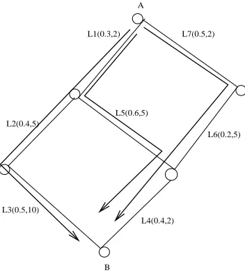
The bottleneck link of a path will shift from one to another based on the traffic demand and link residual capacity; But in the optimal traffic distribution problem, traffic volume for each path is unknown and needs to be determined. An example is shown in Figure 3.2. Each linkLi(i= 1−6)has a label of (ul, cl). The IE pairA−> Bhas traffic demand of 2 to be sent on three paths:p1 ={L1, L2, L3}, p2 =
{L1, L5, L4}, p3 = {L7, L6, L4}. Currently, the bottlenecks on the three paths are L3, L5 and L7,
respectively. But with more traffic transmitted, this may not be the case. Different traffic volume will generate different bottlenecks. This is shown in Table 3.2.
Since the total traffic demand is 2 from A to B, we can ”guess” that {L1, L4, L7} should be the bottlenecks for pathp1, p2andp3, respectively. After determining the bottlenecks for each path, we still
L1(0.3,2) A
L7(0.5,2)
L6(0.2,5) L2(0.4,5)
L3(0.5,10)
B L5(0.6,5)
L4(0.4,2)
Figure 3.2: A simple graph with one IE pairA→B
Table 3.2: Traffic Volume and Bottleneck changing Volume(f1, f2, f3) Bottlenecks(p1, p2, p3)
f1 <0.5, f2 <2/3, f3 :any {L3, L5, L7}
f1 <0.5, f2 >2/3, f3 :any {L3, L4, L7}
f1 >0.5, f2 <2/3, f3 :any {L1, L5, L7}
Figure 3.3:
1) no sharing between the paths; 2) sharing bottleneck;
3) bottlenecks are not shared links and are on different links on different paths; 4). shared link is bottleneck for one path, but not for the other.
For case 1 and 3, each bottleneck is counted in the formula; for case 2, since it’s a shared bottleneck, it’s counted only once; for case 4, there are 2 possible ways:
4.1) use the bottleneck link that’s shared only in the formula, ie, traffic on this link only is equal to the sum;
4.2) use the bottleneck that’s not the shared link for the path and use the next-highest- utilization link for the other path, the sum of their traffic is equal to the sum of demand.
Both the two cases 4.1 and 4.2 are true. But we hope to use the bottleneck which has a LU equal to the optimal MLU. To simplify the equation, we use4.1. This is also because a shared link is more likely to become a bottleneck when more traffic comes in.
Figure 3.3: Bottleneck Grouping
Given a network and traffic demand, in order to minimize MLU, it’s important to fill paths with lower utilization first. Thus, MLU of the current network won’t be increased until the utilization of all paths reach the same value unless all traffic are transmitted. The BALANCE() algorithm (Algorithm 4)is based on this idea and allocates traffic to paths in the order of their utilization. Due to link sharing, multiple paths from multiple IE pairs may have the same utilization. When one of these paths is getting traffic from the IE pair it belongs to and is achieving a higher LU, so are all other paths with the same LU, even though they are not getting any traffic from their own IEs yet.(Note that each path belongs to one IE pair only.) A simple approach that just fills in a random chosen path available in the ordered path list may not work. Thus, an important issue is to choose which IE pair and which path from the IE pair. We define two priority rules for this purpose in the BALANCE algorithm (as shown in Algorithm 4). First, we choose the IE pair with the highest expected optimal MLU estimated from the equation; Second, among multiple paths with the same utilization within each IE pair, we select the path where the bottleneck link has the minimum capacity. The intuition behind the IE pair selection rule is that high expected MLU means the traffic competition is intense and the IE pair should be considered first; Otherwise once the network gets more congested, traffic from this IE pair may increase the congestion level dramatically due to limited routing flexibility. For the rule of low capacity link first, it’s to reduce residual capacity fragmentation. We also tested other approaches, including selecting an IE pair randomly and simply using the next minimum utilization lu(pi−1)as the filling threshold. Our
experiments show that the BALANCE() algorithm works the best, both for optimality and computational efficiency.
After selecting the path to fill traffic, we still need to determine the traffic volume to be filled. Instead of using the expected optimal MLU X, we use max(X, next−minimum−LU), where next−minimum−LU is the next minimum path utilization in the ordered list. This speeds up the computation without increasing MLU. In our simulation, for the largest topology with115nodes, the whole computation only takes less than 1 second. In TEA, each ingress node uses the BALANCE algorithm to distribute traffic from itself to all egress nodes. In addition, inR−f lowsrerouting process, each ingress node also uses the BALANCE algorithm to distribute R-flows.
3.4.4 Probing Traffic Paths
algorithm 4 BALANCE() whileF <|V0
−1|do ***|V0
−1|is the total number of IE pairs;
***F is the number of IE pairs which have their traffic transmitted already; 1). order all paths nondescendingly by LU:
p1, p2, ..., pn, withlu(p1)≤lu(p2)≤...≤lu(pn);
2). select the first set of pathsP with the minimum LU over all paths;
3). select the first pathpi with the next minimum LU
over all paths;
***lu(p1) =lu(p2) =...=lu(pi−1)
4). Calculate expected MLUs for all IE pairs in setP; 5). select the IE pairIEijwith the maximum expected
MLUmax exp mlu;
6). select the bottleneck linklwith minimum capacity from paths ofIEij;
7).lu threshold=max(lu(pi), max exp mlu);
8). fill traffictto paths with bottlenecklup tolu threshold forIEij;
9). splittevenly if multiple paths exists;
***lettijrepresent the transmitted traffic forIEij;
10).tij+ =t;
11). if (tij==Tij)
F + +;
12). update lu for all paths;
*** due to path sharing, utilization of other paths may have changed too
49×10 = 490paths even though the number of links in the network may be less than200. Probing490 paths by eachI-node is very resource intensive but the probing overhead can be dramatically reduced by (1) by picking only a small subset of the paths to probe, mainly the smallest subset covering all links from the24500 paths. As a result, not allI-nodes will need to probe the network, not all24500paths will be probed. (2) By communicating the information revealed by the probing I-nodes to the center node. As a result, the utilization of the links in the24500paths will be known to the center node with much less effort.
TEA relies on a greedy method to select the set of probing I-nodes and the paths to probe. The greedy method can be summarized as follows: LetLbe the set of links inGcovered by thek- shortest paths from allI-nodes to all otherE-nodes. LetLi be the set of links inGcovered by the paths from
I-node, i, to all other E-nodes. LetLi,j be the set of links inGcovered by the paths fromI-node, i,
toE-node, j. Order allI-nodes, pick the one, sayi, which has the largest |Li|. Assign this I-node as
a probing node. In order to identify the paths that this I-node will probe, identify the E-node, say j, which has the largest|Li,j|. Select the path from the paths betweenIE-pair(i, j), which covers more
links inG. Assign this path as a path to be probed by probingI-node,i. Recursively, apply the process to identify the next path to be probed and the next I-node to probe in order to cover the links, which are not already covered by the paths that were selected for probing. Note that this method needs to be deployed only once, as long as the network topology does not change, to identify the probing I-nodes and the probed paths.
The number of probes needed to collect link utilization information and disseminating it to the center node, by following the greedy method is inO(|E|+|V|). TheO(|E|)part is needed since the number of paths to be probed cannot exceed the number of links,|E|, in the network, and theO(|V|) part is used to communicate collected information from probingI-nodes to the center node. Clearly, the probing complexity using this greedy method is much better than probing allk-shortest paths between allIE-pairs, which leads toO(k∗ |V| ∗ |V|)probes.
3.4.5 The TEA Procedure
The TEA procedure is shown in Algorithm 5. After the traffic distribution using BALANCE, TEA reroutes R-flows (also using BALANCE). It will converge when either of the following condition is true.
• When there is no R-flows;
• When threshold value matches MLU;
algorithm 5 Flowchart for TEA(i) {
BALANCE(Ti,k-shortest paths);
Initialize Congestion Threshold(); Core Routers report R-flows;
Reduce R-flows(); // the R-flows set is reduced
While (#R−f lows >0&&T hreshold6=M LU) //converging condition {
BALANCE(R-flows,alternative paths); // use widest paths (excluding bottlenecks) for elephants LU Infer(); //infer network state;
calculate alternative paths for R-flows; Adapt Congestion Threshold();
Core Routers report R-flows; //using the new threshold }
}
ISPs has shown that they may be only concerned about elephants [47]. In this way, traffic measurement overhead is reduced to a large degree by tracking a subset of flows only. In our experiments, the total number of R-flows is less than5%. Core routers detect R-flows based on the threshold, which deter-mines how many routers need to monitor how many flows, but only routers with bottlenecks need to do this. The communication overhead in TEA includes:
• link utilization reporting from all core routers to the center node; • R-flows reporting from congested core routers to the center node;
• Information exchanging from the center node to the ingress nodes, including reduced R-flow sets, new path set for R-flows and the corresponding path bottlenecks and bottlenecks for all other paths.
3.5
Performance Evaluation
3.5.1 Simulation Setup
traffic going from one ingress node to one egress node is proportional to the total traffic destined to that egress.
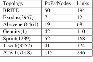
For the BRITE topology, there are 50 nodes in the network, each of which is both an ingress and an egress node. This is an extreme test case in that path competition is much more intense than that when there are less ingress and egress nodes. We use 10 random BRITE topologies, on each of which 5 different traffic matrices are randomly chosen, with optimal MLU ranging between 20% and 80%. For each Rocketfuel topology, we choose 10 random sets of ingress& egress nodes, which are the same as the original POPs set except that 2 randomly chosen nodes are left out; then for each of the 10 sets, 5 different traffic matrices are generated with optimal MLU ranging between 20% and 80%. We compute the optimal MLU using MATLAB’s linprog function.
Performance Metrics include MLU(maximum link utilization in the network), MLU ratio(the ra-tio of MLU over the optimal MLU), convergence time(number of round trip times) and rejected traf-fic(traffic may not be accommodated if MLU is larger than 1).
Table 3.3: Topologies Topology PoPs/Nodes Links
BRITE 50 194
Exodus(3967) 7 12
Abovenet(6461) 19 68
Genuity(1) 42 110
Sprint(1239) 52 168 Tiscali(3257) 41 174 AT&T(7018) 115 296
3.5.2 Performance of TEA
In this section we show the performance of the BALANCE algorithm and compare it with OSPF and K-Shortest, where each path simply gets an equal share of the traffic. The results on the seven topologies are shown in Figure 3.4. It’s averaged over 50 runs and the optimal MLU is around 75% representing a high traffic competition case. From the figure we know that the BALANCE algorithm can bring down MLU to a large degree and give a much better starting point than others. A random distribution like K-Shortest can get very high MLU. Interestingly, the results also show there are significant differences among different topologies. For example, for Exodus, all can achieve the optimum, while traffic com-petition on BRITE and some other Rocketfuel topologies may be intense and more sophisticated traffic engineering approaches may be needed.
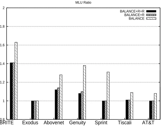
(Reduce). The contribution of each scheme is shown in Figure 3.5. It’s averaged over 50 runs with opti-mal MLU ranging over 20-80%.BALAN CE+R+Ruses all three schemes;BALAN CE+Ruses BALAN CE and Rerouting withoutReduce. The results shows that both Rerouting and Reduce can reduce MLU further and the degree of variation depends on different topologies. Interestingly, the results here may give a hint for level of traffic competition on different topologies. On Abovenet and Genuity, all three schemes are needed to reduce MLU close to the optimum; On Tiscali, Sprint and AT&T, theReroutingstep can bring MLU close (or equal) to the optimum; while on Exodus, only the BALANCE step is needed to get an optimal distribution. Among all, Brite has the worst performance.
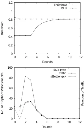
A sample run from AT&T topology is shown in Figure 3.6, including the number of R-flows and its fraction of traffic, the number of bottlenecks, the threshold value and MLU at each round. The optimal MLU is around 0.8 representing a highly intense test. TEA reaches the optimum in 2 rounds, and the threshold value converges to the MLU in less than 10 rounds. As shown in the figure, the number of R-flows is less than 1%(100/(115∗114)) (which takes up to 33% of total traffic), so the rerouting overhead is limited in TEA. The total number of bottlenecks is less than 40(less than 15%, with a total number of 296 links in the AT&T topology.) Generally TEA needs less than 10 rounds on all topologies in our experiments.
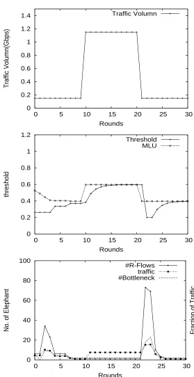
Traffic matrices may change during converging process, which can be handled by the rerouting procedure since ingress nodes can get an updated view in this process. Every selected R-flow will be rerouted targeting a balanced load over all its available paths. A sample run from Sprint is shown in Figure 3.7. At round 3, TEA reaches optimal MLU 0.40; at round 10, traffic from a R-flow is increased from 0.15 to 1.15, which may increase MLU by 40% since the bottleneck link capacity is 2.5 without traffic redistributing. TEA will reroute this R-flow using available paths in the network and reaches new optimal MLU 0.6 right after the traffic increasing. At round 20, the traffic is decreased from 1.15 back to 0.15, which will bring the MLU down to 0.4 and the threshold value back to 0.2. As shown in the figure, threshold value converges to the new optimal value at round 30. Also included in the figure are the fraction of traffic from the R-flows and the number of bottlenecks. The total number of R-flows is less than 80(≤3%,80/(52∗51)of the total number of IE flows), with a traffic volume of less than 10%; the total number of bottlenecks is less than 30.
3.5.3 Comparing with TeXCP
1 2 3 4 5 6 7
AT&T Tiscali
Sprint Genuity Abovenet Exodus
BRITE
MLU Ratio
K-Shortest OSPF BALANCE
Figure 3.4: MLU comparison between BALANCE,OSPF and k-shortest
0.8 1 1.2 1.4 1.6 1.8 2
AT&T Tiscali
Sprint Genuity
Abovenet Exodus
BRITE
MLU Ratio
BALANCE+R+R BALANCE+R BALANCE
0 0.2 0.4 0.6 0.8 1 1.2
0 2 4 6 8 10 12
threshold
Rounds
Threshold MLU
0 20 40 60 80 100
0 2 4 6 8 10 12
No. of Elephants/Bottlenecks
Fraction of Traffic
Rounds
#R-Flows traffic #Bottleneck
0 0.2 0.4 0.6 0.8 1 1.2 1.4
0 5 10 15 20 25 30
Traffic Volumn(Gbps)
Rounds
Traffic Volumn
0 0.2 0.4 0.6 0.8 1 1.2
0 5 10 15 20 25 30
threshold
Rounds
Threshold MLU
0 20 40 60 80 100
0 5 10 15 20 25 30
No. of Elephant Fraction of Traffic
Rounds
#R-Flows traffic #Bottleneck
simple even distribution with 10-shortest can reach the optimum for Exodus.
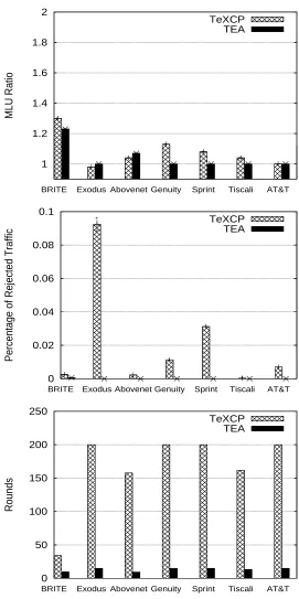
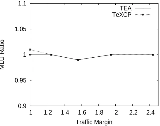
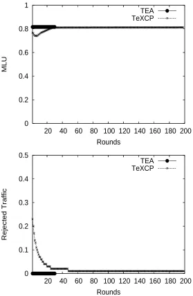
Figure 3.9 shows how the performance changes on AT&T topology when the original traffic matrix is multiplied by some constant(traffic margin). It shows TEA can scale with different traffic matrices and has close MLU ratio with TeXCP. Figure 3.10 shows the convergence of TeXCP and TEA when optimal MLU=0.82 for AT&T topology. It shows TEA can converge to the final MLU quickly without rejecting traffic. Due to the random initial traffic distribution, TeXCP rejects more than 20% traffic in the beginning. We found that after 200 rounds TeXCP still rejects traffic(less than 1%) and it may need thousands of rounds to accept all traffic. In our simulations, we use an even traffic distribution over all paths (same as ”K-Shortest”) as the starting point in TeXCP. TeXCP will move traffic from the high utilized paths to lower utilized paths. In case the starting point is a skewed distribution where no traffic is transferred on the low utilized paths, the volume of traffic to be moved is equal to , a parameter defined in the TeXCP paper [23], which could be a very small number. In this case the convergence would rather take a long time in TeXCP.
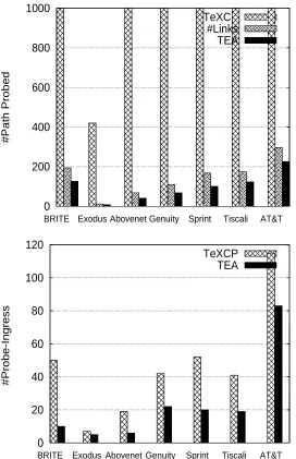
Figure 3.11 compares the probing overhead in TeXCP and TEA. In TeXCP, each ingress node probes all IE paths periodically. So for a network of 50 ingress nodes and each IE pair using 10-shortest paths, the total number of probed paths would be as high as 24500(50*49*10). As mentioned in TeXCP, when the network is getting large(100+), the core routers can report link utilization to ingress routers periodically, which still incurs a message overhead of|V| ∗ |E|. In TEA, we propose a greedy method to involve less ingress nodes and probe less paths. The results are shown in Figure 3.11. It shows the total number of paths to be probed is dramatically decreased comparing to that in TeXCP; it’s less than the total number of links in the network. The number of probing ingress nodes is reduced too.
3.6
Related Work
Lot of work has been done on traffic engineering, including traffic matrix measurement, bottleneck statistics and traffic engineering methods. Existing TE approaches can be categorized based on whether they can work with the current OSPF/IS-IS framework, or with the MPLS framework, or with both. TE with MPLS should have a better control over traffic flow for a whole ISP network. Though hop-by-hop proposals can be easily implemented in current OSPF/IS-IS networks in a distributed way, performance is still a problem, especially when the objective is to minimize the MLU; another issue is whether it’s really necessary to have core routers perform the same TE functionality as that by edge routers. Generally ingress routers could have a better control on traffic flow. Since edge routers, especially ingress routers, have more traffic information, they should have more TE responsibility.
1 1.2 1.4 1.6 1.8 2 AT&T Tiscali Sprint Genuity Abovenet Exodus BRITE MLU Ratio TeXCP TEA 0 0.02 0.04 0.06 0.08 0.1 AT&T Tiscali Sprint Genuity Abovenet Exodus BRITE
Percentage of Rejected Traffic
TeXCP TEA 0 50 100 150 200 250 AT&T Tiscali Sprint Genuity Abovenet Exodus BRITE Rounds TeXCP TEA
0.9 0.95 1 1.05 1.1
1 1.2 1.4 1.6 1.8 2 2.2 2.4
MLU Ratio
Traffic Margin TEA TeXCP
Figure 3.9: MLU Ratio with Traffic Margin
To our best knowledge, not many on-line distributed methods have been proposed, TeXCP [23] and MATE [11] are the most recent ones. TeXCP [23] uses the 10-shortest paths to distribute traffic and probes the paths periodically to gather bottleneck bandwidth information. Based on the feedback, TeXCP uses additive-increase multiplicative-decrease(AIMD) to update traffic allocation on each path. In addition, TeXCP proposes a load-balancer which recalculates the traffic ratio at each ingress router periodically. Stability is proven in TeXCP. Though network probing can provide updated information in TeXCP, the 10-shortest paths are not changed according to network dynamics which may not achieve close-to-optimal maximum link utilization(MLU) all the time. When paths with high and low utilization form two independent sets without path sharing, traffic shifting is constrained within each set and thus will not decrease MLU any more, thus paths in the set with low utilization are not fully utilized; As shown in the experiments, the load balancer may take a long time to converge. It moves traffic gradually from one path to another to bring down MLU within each IE pair without considering how much more traffic will be shifted among different IEs. In experiment, this may take 5000 rounds to achieve 10% from optimal MLU.
MATE [11] tries to minimize a chosen cost function and uses the standard gradient-projection al-gorithm to update the traffic allocation vector by calculating the derivative length of links. It extends the model to handle asynchronized and delayed updates; it also proposes how to measure the network accurately.
0 0.2 0.4 0.6 0.8 1
20 40 60 80 100 120 140 160 180 200
MLU
Rounds
TEA TeXCP
0 0.1 0.2 0.3 0.4 0.5
20 40 60 80 100 120 140 160 180 200
Rejected Traffic
Rounds
TEA TeXCP
0 200 400 600 800 1000
AT&T Tiscali Sprint
Genuity Abovenet Exodus
BRITE
#Path Probed
TeXCP #Links TEA
0 20 40 60 80 100 120
AT&T Tiscali Sprint
Genuity Abovenet Exodus
BRITE
#Probe-Ingress
TeXCP TEA
these flows; and how to allocate network resources between long-lived flows and short-lived flows. To detect long-lived flows, the paper proposed that the flow trigger for long-lived flows detection should be chosen such that the residual lifetime of the long flows should be large relative to the link-state update period. To select paths for long flows, the widest path is chosen from the paths of equal length(in terms of hops, which is limited to one more hop than the shortest path). To reserve link bandwidth for short flows, the paper proposed that the long flows should be limited to some portion of the total link capacity, which can be determined by the flow trigger and traffic distribution. Though this is also a hybrid approach routing long flows and short flows differently, the paper mainly focuses on design issues, while the TEA approach focuses on traffic allocation on multiple paths and on how to reduce rerouting effort.
There are some other approaches including the oblivious method [1], COPE [45], and OSPF-TE [16]-[18]. Oblivious method [1] provides a linear-programming approach to achieve near optimal per-formance with no knowledge of traffic demands. COPE [45] proposes a linear-programming approach to optimize performance for expected traffic demand scenarios while providing a bounded performance ratio for unexpected traffic environment. OSPF-TE approaches use local search to find an appropri-ate weight setting, where search directions are guided by hash tables with dimensional integer vectors. OSPF-TEs also propose how to handle link failures and adapt to network dynamics. Another work on weight setting is [31]. The paper proposes a Tabu-search heuristic to find appropriate link weights considering SLA agreements and link failure events. The algorithm selects link weights that can work well without changing under failures. To validate the heuristic, the paper formulates an Integer Linear Program (ILP) model to provide a lower bound and show that the heuristic is within 10% of the optimal bound.
Other approaches targeted at traffic engineering in existing OSPF/IS-IS framework include [15, 42, 47, 21], where REPLEX [15] can also work with MPLS. In [42], schemes are proposed on how to use destination-based traffic forwarding with equal splitting in current OSPFIS-IS framework while still maintaining an optimal MLU. In [21], the paper proposed a scheme named AMP (Adaptive Multi-Path routing). In AMP, each router has a local view which concerns only its directly connected neighbors and works in a distributed way. The neighboring routers use BMs(Backpressure Message) to exchange link load information, which includes the ”effective equivalent load” metrics and link load information. Functions are defined in AMP on how to calculate the ”effective equivalent load” and link load informa-tion. In AMP, each router needs to maintain an ”In/Out Matrix” to calculate the traffic arrived from each neighbor on each link, which is an indication of how much each neighbor contributes to the congestion. The load balancing is performed per destination. The traffic shifting will increase exponentially when the direction of load shifts persists, on which no details are provided in the paper. According to our categorization, AMP is a hop-by-hop scheme working with OSPF/IS-IS framework, instead of MPLS.
link utilization(LU) information, and properties relating to traffic dynamics adapting and convergence. Another direction of research that may be related to TE is QoS routing, which may also focus on traffic distributing, but target at different optimization objectives other than to minimize MLU. Lot of work has been done on QoS routing, including [30], [27], [24], [29], etc...
In the most recent work [24], a new oblivious method is proposed. The paper propose a two-phase routing scheme to handle traffic variation with guaranteed performance. All Traffic is sent to a set of intermediate nodes before being sent to the final destinations. To handle traffic variation, the paper uses the hose model [14] in which traffic that enters (leaves) an ingress (egress) node in the network is bounded by the total capacity of all external ingress(egress) links at that node. So the hose traffic model can accommodate naturally a network’s ingress-egress capacity constraints. The paper formulates the linear programming problem that optimizes the throughput. It also provides a fast combinatorial algorithm to the optimization problem with a proven approximation factor. Several applications are discussed in the paper that fit into the proposed scheme, including VPNs, specialized service overlays like the Internet Indirection Infrastructure (i3), network-based middlebox routing, and IP-over-Optical networks to handle extreme traffic variability without dynamic reconfiguration, etc...
In [30], the paper proposes an adaptive proportional routing scheme using only a localized net-work state. It’s mentioned in the paper that routing with a global view may lead to synchronization problems such as route flapping. The approach in this paper targets at blocking probability minimiza-tion using Erlang’s Loss Formula, which is quite different from the TEA approach. First a theoretical scheme named vcr (virtual capacity routing) is proposed, which calculates the virtual capacity using the inverse of Erlang’s Loss Formula with an objective blocking probability and iteratively search the solution space. The theoretical vcr approach has two problems including intense computation and the observation of accurate block probability as an input. To avoid these problems, a practical approach named pcr(proportional sticky routing) is then proposed in the paper. The pcr approach can calculate the block probability easily. Although both pcr and TEA uses proportional routing, the objective is different: pcr targets at minimizing the blocking probability, while TEA minimizes the maximum link utilization.
In [29], the paper proposes a wdp(widest disjoint paths) scheme to select paths for proportional multipath routing. The paper defines two important metrics for paths quality including the width and the distance. The wdp scheme dynamically updates the paths set using global network state information, and is combined with another ebp(proposed in [6]) proportional routing scheme to minimize the blocking probability. It’s shown in the paper that wdp can achieve close-to-optimal performance while incurring less overhead in the network. Comparing with the TEA approach, this paper focuses on how to select paths, instead of how to distribute traffic among a set of paths.
resources in the network. The presented approach can achieve near optimal performance in a distributed way even when the link state update interval is large.
Table 3.4: Overview
Approach TM LU dynamics adapting Adapting: Rerun? Bounded Convergence
LP traffic matrix Yes No Yes N/P
TeXCP traffic vector Yes Yes Yes No OSPF-TE traffic matrix Yes No Yes N/P MATE traffic matrix Yes Yes Yes No TEA traffic vector Yes Yes Minimum rerouting Yes
3.7
Concluding Remarks
Chapter 4
Traffic Engineering without Global
Network State
4.1
Introduction
Various network engineering applications need link utilization as an input, such as traffic engineering schemes, traffic inference, capacity planning, etc... Link utilization information is generally available through SNMP protocol [22] which reports link utilization every 5 minutes; A network management station can collect and analyze this information. But in real networks, it’s still difficult to gather an accurate global network state due to the following reasons:
1. It’s difficult to get a synchronized view for all the physical links at the same time; The delay for link utilization reports from different locations around the network to the collecting station will vary;
2. Reports may be lost; Currently SNMP uses UDP as the transport protocol which is not reliable; 3. Link utilization varies over time and it’s challenging to keep this information updated at a
collect-ing station all the time;
4. It’s resource consuming to report link utilization for the whole network periodically.
can be recovered and network management overhead can be reduced. We show that with this inferred approximate link utilization information traffic engineering can still achieve good performance.
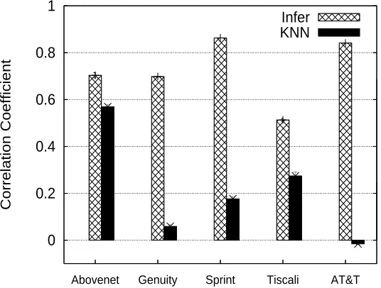
Lot of work has been done on traffic matrix inference for traffic engineering, including [28], [50], [51], just naming a few here. To our best knowledge, link utilization inference has never been done before. Although link utilization can be calculated from traffic inference, our approach will estimate link rate directly without measuring traffic matrix. By using a few number of known links the proposed inference algorithm can estimate link rate for the unknown links. The performance is compared with the existing interpolation methods. Our experiments show that the inference algorithm can achieve a much higher correlation coefficient with an absolute error around a few percent.
The rest of this chapter is organized as follows: Section 4.2 provides background on utilization inference for traffic engineering; Section 4.3 describes the inference algorithm; Section 4.4 provides experimental results; And Section 4.5 concludes this chapter.
4.2
Background
4.2.1 Traffic Engineering
Traffic engineering schemes operate on traffic matrices and determine the traffic distribution for the net-work, which will determine the traffic load on each link. The routing table is related to the link load by the following linear equation:
AX =Y (1)
where matrixA = {aij}is the routing table with dimensionm∗n, of whichm = |E| is the number
of links in the network,nis the number of the ingress-egress(IE) pairs as traffic sources; aij is a value
from the range[0,1]which represents the fraction of traffic from IE pairjon linki;X ={xj}is a the
traffic rate vector, withxj representing traffic rate from IE pairj;Y ={yi}is the aggregated link rate
vector, withyi=Pj=1−naij∗xjrepresenting the total link rate on linkifrom all traffic sources inX.
LetU ={ui}be the link utilization vector, withuibeing the link utilization on linki, and letC ={ci}
be the link capacity vector, withcibeing the link capacity of linki, we have:
Y =U·C
where·is the element wise multiplication withyi =ui∗ci.
One main objective of traffic engineering is to minimize maximum link utilization(MLU) in the network. LetU∗
be the optimal MLU, we have: AX =Y =U1∗C≤(U∗−U0)∗C
whereU0 andU1represent the existing and additional link utilization (from the new traffic vectorX to
the equation above we know that for each linkiso long asui0+ui1 ≤U∗, the optimal MLU remains
the same with the same routing table for traffic allocation. Thus we can have a range for the existing ui0:
ui0≤U∗−ui1
LetU0,U¯0represents the accurate and estimate link utilization, respectively. Existing traffic engineering
approaches assume the global network utilizationU0is available and accurate. In this paper, we propose
an inference method which assumes only a small subset of link information available and estimates utilization for the other links using known links and the routing table.
4.2.2 The Utilization Inference Problem
Given a subset of links E1 = {li}, i = 1−k, withk being the number of known links, for which
accurate utilization is known, we want to know the utilization for the remaining links E−E1. From
E1, we have a subset of linear equations from the above equations (1):
AX =Y1
whereAis the corresponding routing table for links E1. Let the routing table for the remaining links
E−E1beB, with the equations as follows:
BX =Y2
The utilization inference problem is to estimate the link rate vectorY2without knowing the traffic vector
X. This is an interpolation problem. The optimal case is that for each vectorb0
i(bi: one row inB,b0i:
the transpose ofbi), it can be formed by a combination of vectorsa0iinA
0
(ai: one row inA) as follows:
A0
r =b0
i,∀i∈[1, m−k]
which meansb0
i ∈ Range(A
0
), there is a solution r to the linear equations. But generally this is not the case for current networks, since the linear equations are over-determined with the dimension ofA0
beingn∗k, wheren k. One approach that’s often used for this interpolation problem is KNN(K-Nearest Neighbors), which finds the closest neighbors forb0
i and uses a weighted sum of the neighbors
to approximateb0
i. As a comparison base, we uses a similar approach as in [51] and [3], with Euclidean
distances and a weight equal to the inverse of the distance.
4.3
The Inference Algorithm
To infer link utilization, we need to answer the following three questions:
1. Which links to be known;