Vol. 4, Issue 11, November 2015
Optimization of Grain Layer Thickness in the
Design of Solar Grain Dryer through
Simulation
Mr. Booker Osodo
1, Prof. Daudi Nyaanga
2, Dr. Jeremiah Kiplagat
3, Dr. George Owino
4ecturer, Department of Industrial and Energy Engineering, Egerton University,
B. Osodo, Nakuru,
Kenya1Associate Professor, Department of Agricultural Engineering, Egerton University,
D. Nyaanga, Nakuru,
Kenya2Principal, Kenya Power and Lighting Company Training School,
J. Kiplagat, Nakuru,
Kenya3 Lecturer, Department of Industrial and Energy Engineering, Egerton University,G. Owino, Nakuru,
Kenya4ABSTRACT: Forced convection solar dryers, utilizing solar driven fans, may be used to improve ventilation, and to
achieve an optimum drying air velocity in grain dryers. However, without use of the appropriate grain layer thickness, the heated air may not be able to successfully penetrate the grain to facilitate drying. Also, too many grain layers placed in the drying cabinet may prevent air from flowing up the entire drying cabinet. The appropriate grain layer thickness and maximum number of drying trays are therefore factors that are crucial in sizing a solar drying cabinet. However, their determination, without use of simulation, would require troublesome development stages, involving trial and error and continued testing, a process which would be expensive and time consuming. This study applied simulation using Comsol Multiphysics Software for their determination, hence enabling the sizing of a dryer cabinet to facilitate sufficient and effective aeration of the grain for optimization of the drying process. It was found that the maximum grain layer thickness that can allow penetration by air is 100 mm. It was also found that the maximum number of grain layers that should be dried for effective aeration was 4.
KEYWORDS: Optimisation, Solar Drying, Grain Layer Thickness, Comsol Multiphysics Software, Deep bed drying.
I. INTRODUCTION
In developing countries, post-harvest food losses are estimated to be of the order of 40%, but can rise to be as high as 80% under very adverse conditions. A significant percentage of these losses is related to improper and, or untimely drying of foodstuffs, since one reason for loss of grain after harvesting is spoilage resulting from high moisture content, according to the authors in [4] and [5]. In [3] and [6], it is stated that incidences of post-harvest food loss in Kenya have been estimated at 30%, and can rise to be as high as 100% with the advent of afflotoxin. Drying of maize to below 13.5% moisture content increases storage life and maintains quality by decreasing growth of fungi and insect infestation during storage. It also prevents germination.
ISSN(Online): 2319-8753
ISSN (Print) : 2347-6710
International Journal of Innovative Research in Science,
Engineering and Technology
(An ISO 3297: 2007 Certified Organization)
Vol. 4, Issue 11, November 2015
An optimum air flow rate is essential for achieving a satisfactory dryer performance. Slower air flow rate may increase drying air temperature while higher air flow rate may decrease moisture removed, according to the authors in [1] and [9].In [11],it is stated that factors affecting drying rate include air temperature, air velocity and grain layer thickness, among others. Thus, without knowledge of the optimum air velocity and grain layer thickness for optimum drying rate and for ensuring no damage to the grain, optimum performance of a solar grain dryer will not be attained, as stated in [13]. In [8], it is shown that typical air flow rates range from 0.25-0.51 m3/ s m2of perforated screen area, these flow rates creating relatively low static pressures of 0.249-1.25 kPa in cross flow and mixed-flow dryers.
A grain layer thickness that allows air to flow through the grain at an optimum rate is therefore essential if the drying process is to be effective. Determination of this thickness is crucial in the proper design of a grain dryer. Knowledge of the grain layer thickness, and hence also height of void space, enables determination of drying cabinet dimensions, once the number of layers penetrable by the air is determined. However, determination of these parameters, without use of simulation, would require troublesome development stages, involving trial and error and continued testing, a process which would be expensive and time consuming. This study applied simulation using ComsolMultiphysics software for their determination. This enabled the sizing of a dryer cabinet to facilitate sufficient and effective aeration of the grain for optimization of the drying process.
II. PERFORMANCE OPTIMIZATION
Simulation was carried out of hot air flowing through a single grain layer of 50mm thickness, at an air velocity of 1m/s. A parametric sweep was then carried out in order to simulate air flow through different grain layer thicknesses ranging between 50 mm - 300 mm. This was in order to determine the optimal grain layer thickness that would allow the fan to overcome the static pressure resulting from airflow. Once the optimal grain layer thickness was determined, simulation to determine the pressure drop up a single layer of grain was done. The number of layers was then increased gradually to study the pressure profiles for increasing number of layers, in order to determine the number of drying trays that would be used in the dryer to allow air penetration up the drying chamber. The assumption made was that the grain behaved like a packed bed. According to [7] and [10], fluid flow through a packed bed may be described using the Ergun equation (eq. 1). According to this equation, pressure drop along a packed bed given some fluid velocity depends on packing size, length of bed, fluid viscosity and fluid density.
+
(1)Where
Pressure drop µ = Absolute viscosity of fluid
= Length of bed = Effective diameter of particles assumed to be equivalent to spheres
Fractional void volume of bed Density of fluid
= Superficial fluid velocity
III.EXPERIMENTAL SET-UP AND RESULTS
Airflow up single layers of various thicknesses ranging between 50mm-300mm, at 50 mm intervals, were simulated. In each case, the inlet air velocity of 1m/s was used. In the case of grain layer thickness of 50mm,as shown in fig.1, a linear increase in air velocity up the grain layer until an approximate height of 2.3 mm was observed, after which the air velocity fell. The air velocity was also much lower than the inlet velocity (between 0.034 – 0.07 m/s for inlet velocity 0f 1 m/s). This showed that the static resistance to air flow was much higher than the fan could overcome, suggesting that this would not be an appropriate grain layer thickness.
Vol. 4, Issue 11, November 2015
(Fig. 1 Air Velocity Up 50 mm Thick Layer) (Fig. 2 Air Velocity up 100 mm Thick Layer)
For a grain layer thickness of 100 mm shown in fig.2, air velocity increased gradually up the entire grain layer, levelling off at the top implying that this would be an appropriate grain layer thickness for the dryer, and that the suction fan would be able to overcome the static pressure.
For grain layer thickness of 150 mm in fig.3, the graph showed that the air completely failed to flow up the grain layer. This was probably because the suction fan was totally unable to overcome the static pressure (resistance to airflow). Thus, this would not be an appropriate grain layer thickness to use for the dryer. Fig.4 shows that for grain layer thickness of 200mm, air velocity increased up to a grain layer height of 40 mm, before falling sharply. Air velocity was again observed to be increasing sharply at the upper section of the grain layer. However, because the expectation was for the air velocity to rise steadily up the grain layer, it was concluded that this was also not an appropriate grain layer thickness to use.
(Fig. 3 Air Velocity up 150 mm Thick Layer) (Fig. 4 Air Velocity up 200 mm Thick Layer)
ISSN(Online): 2319-8753
ISSN (Print) : 2347-6710
International Journal of Innovative Research in Science,
Engineering and Technology
(An ISO 3297: 2007 Certified Organization)
Vol. 4, Issue 11, November 2015
(Fig. 5 Air Velocity up 250 mm Thick Layer) (Fig. 6 Air Velocity up 300 mm Thick Layer)
In the case of 300mm grain layer thickness in fig.6, once again air velocity increased up the grain layer, but the increase was not sustained. The velocity dropped way before the top of the grain layer, at a height of about 200 mm. This showed that this was not an appropriate grain layer thickness to use.
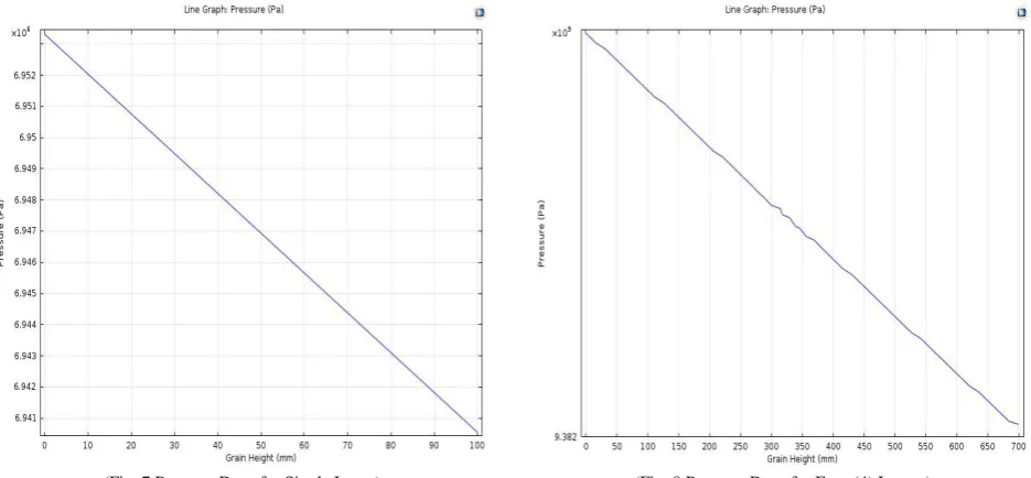
Fig. 7 is a graph showing pressure drop for a single 100 mm layer. It indicates that there is a linear drop in pressure from the lower section of a grain layer upwards, the total pressure drop for a 100 mm single layer being 1.2 x 10⁴ Pa. There is a similar trend as the number of grain layers is increased until the number of layers is 4, as shown in fig. 8.
(Fig. 7 Pressure Drop for Single Layer) (Fig. 8 Pressure Drop for Four (4) Layers)
Vol. 4, Issue 11, November 2015
(Fig. 9 Pressure Drop for Five (5) Layers) (Fig. 10 Pressure Drop for Eight (8) Layers)
This trend intensifies to the extent that for 16 grain layers and beyond, there is no pressure drop at all showing no air flow through the grain layers. This, for example, is shown in fig. 11 for 16 layers.
IV. CONCLUSION
It was concluded that the grain dryer should be loaded with a maximum of 4 trays, each with grain layer thickness of 100 mm. These conditions, if applied, would allow sufficient aeration of the grain and hence facilitate effective drying.
V. ACKNOWLEDGEMENT
ISSN(Online): 2319-8753
ISSN (Print) : 2347-6710
International Journal of Innovative Research in Science,
Engineering and Technology
(An ISO 3297: 2007 Certified Organization)
Vol. 4, Issue 11, November 2015
REFERENCES
[1] Afriyie, J.K., Nazha, M.A.A., Rajakaruna, H. & Forson, F.K. (2009). Simulation and Optimisation of the Ventilation in a Chimney Dependent Solar Crop Dryer. Solar Energy 4: 1560-1573
[2] Akinona, O.A., Akinyemi, A.A. & Bolaji, B.O. (2006).Evaluation of Traditional and Solar Fish Drying Systems towards Enhancing Fish Storage and Preservation in Nigeria. Fish International: Pakistan 1(3):44-49
[3] Barawal, P. &Tiwari, G.N. (2008).Grape Drying by Using Photovoltaic Thermal (PV/T) Green House Dryer: An Experimental Study of Solar Energy. Solar Energy. 62(12): 1131-1144.
[4] Bolaji, B.O. &Alalusi, A.P. (2008).Performance Evaluation of a Mixed Mode Solar Dryer. AU.J.T 11(4):225-231.
[5] Hodges, R.(2009). Supplying Cereal Grain Postharvest Losses Information: the Examples of ALPHIS (African Postharvest Loss Information System. Natural Resources Institute, UK. Retrieved from http:/www.rsis.edu.sg/nts/doc/session%20420Hodgespdf on 13th May 2013 [6] Irungu, J. (2010) Post Harvest Challenges to Food Security in Kenya. A paper presented at KCB Leadership
Center, Karen, Nairobi
[7] Jia, Y., Li, Y. & Hlavka, D. (2009).Flow through Packed Beds.http:/ www.me .rochester.edu/courses/ME241/11-sand.pdf
[8] Maier,D.E. & Bakker-Arkema, F.W.(2002).Grain Drying Systems.Paper presented at Facility Design Conference of Grain Elevator and Processing Society held on July 28-31 in St Charles, Illinois,USA
[9] Murthy,M.V.R.(2009). A review of new Technologies, Models and Experimental of Solar Dryers. Renewable and Sustainable Energy Reviews 835-844
[10] Sachdeva, S., Pareek, S.,Mahadevan, B.& Deshapande, A.(2012).Modeling and Simulation of Single Phase Fluid Flow and Heat Transfer in Packed Bed. Proceedings of 2012 COMSOL Conference, Bangalore
[11] Sevik,S.(2013).Design, Experimental Investigation and Analysis of a Solar Dryer System. Energy Conversion and Management 68:227-234 [12] Tiwari, G.N. (2002).Solar Energy: Fundamentals, Design, Modeling and Applications. Parybourne:Alpha Science International Limited [13] Wilcke, W.F. & Morey,R.V.(2015).Selecting fans and determining airflow for crop drying, cooling, and storage. Retrieved September 2015