RESEARCH FOR ELASTO-PLASTIC DEFORMATION OF PIPING SYSTEM UNDER
SEISMIC CONDITION WITH ELASTO-PLASTIC FE ANALYSIS PROGRAM
Nobuyoshi IRIKI
1),
Toshiaki HISADA2)
Hiroshi WATANABE 2), Tetsundo NAKATOGAWA3),
and Koichiro OKETANI ~) 1) Kobe Shipyard & Machinery Works, Mitsubishi Heavy Industries, Ltd., 1-1, Wadasaki-cho, 1-chome, Hyogo-ku, Hyogo, 652-8585, JAPAN2) School of Engineering, The University of Tokyo, 7-3-1, Hongo, Bunkyo-ku, Tokyo 113-0033, JAPAN 3) OBAYASHI CORPORATION, 1-19-9, Tsutsumi-Dori, Sumida-ku, Tokyo 131-8510, JAPAN
A B S T R A C T
This study investigated the elasto-plastic and dynamic behavior of a piping system with our elasto-plastic FE analysis program [ 1 ]. Especially, in this analysis, the input seismic wave was multiplied as five times of the seismic wave caused by the extreme design earthquake, because of investigating the extreme behavior of a piping system as a whole. Through the numerical results, we observed the cross-section deformation and strain progression of the piping system. And we observed no extreme strain progression on the pressurized boundary.
I N T R O D U C T I O N
At present, as a reasonable seismic design approach for near future, the researches for nuclear power plants is progressing in the direction of allowing acceptable and/or controlled plastic deformation in a piping system. On the other hand, the postulated seismic loads for design will be reevaluated and set higher in near future. As these backgrounds, we need to investigate the strain progression and the deformation of a piping system at the time of a large earthquake, in order to ensure safety and reliability.
Thus, provided the input seismic wave was multiplied as five times of the seismic wave that was caused by the extreme design earthquake at the operation floor level of a reactor building in a nuclear power plant, we performed the extreme response analysis of the piping system with the elasto-plastic FE analysis program.
This program was developed in our previous paper in SMiRT-15 [ 1 ] and had been improved. This analysis employed two kinds of finite element; pipe finite element and 3D finite solid element. To simulate the dynamic behavior of the piping system as a whole, we used elasto-plastic pipe finite elements at the locations where the strain is comparatively small and elasto-plastic solid finite elements at the locations considered susceptible to ratcheting. And we performed an analysis by combining them with the penalty method. For these reasons, this program can simulate, in real time, the elasto-plastic and dynamic behavior of a piping system, including local ratcheting.
Here, ratcheting is a phenomenon in which, for example, local plastic strain accumulates in parts of piping systems due to cyclic loading under intemal pressure. When it occurs in an actual piping system, cracks appear and propagate from the points of crack initiation, and there are many cases where breakage resulted [2].
OUTLINE OF D Y N A M I C E L A S T O - P L A S T I C FINITE E L E M E N T ANALYSIS
F O R M U L A T I O N OF ELASTO-PLASTIC M A T E R I A L
Our program has two kinds of finite element; pipe finite element and 3D finite solid element. In principle, both of them are based on the same formulation of the elasto-plastic material. Provided that the elasto-plastic strain e ep is additionally decomposed into elastic strain e ~ and plastic strain e p, the elasto-plastic constitutive equation is derived by extending Hook's law with the assumption of associated flow rule based on von Misses' equivalent stress. As a material model for ratchet analysis, we employed kinematics hardening including the nonlinear Ziegler law.
Hook
law: (~ij--ceijke(eke -~pke) --cePijke ekl
Here, C e and C ep denotes the elastic constitutive tensor and the elasto-plastic constitutive tensor.(1)
SMiRT 16, Washington DC, August 2001 Paper # 1320
Von Misse~' equivalent stress:
1
¢ ¢ 2
O" - - ~ i j 8 i j
1
'Uij - - U i j - - O~ ij, U£j - - U i j - - - ~ U k k ~ i j
Yield function: F : (~ Sy OF A s s o c i a t e d flow rule: "P -- ,~ e ij
~ ( l i j
N o n l i n e a r Ziegler e v o l u t i o n law: &ij = ~
(2) (3)
(4)
( C i u i j - - C20tij) (5)
To extend this classical elasto-plastic constitutive equation to cover finite deformation, our research takes the following approach. Provided that the velocity vector v of a material point is considered to be given by the sum of the elastic component v e and plastic component v p, i.e., v = v e + v p, the decomposition as D = D e + D p is established with a deformation rate tensor D obtained from the symmetric components of a velocity gradient tensor L. So the stress rate ~j and strain rate
eij are changed to Tij and Dij as follows.
eij are changed to Tij and Dij as follows.
'~l-" ij - - - C ep ijkg D k e (6)
Here, CePijke is derived by extending C ep to finite deformation.
This study uses the elasto-plastic constitutive equation defined by the relationship between the Jaumann rate of the relative Kirchhoff stress and the deformation rate tensor D, so as to consider the geometric nonlinearity as a material objectivity and achieve the stationary potential condition of the virtual work equation. The Jaumann rate of the relative Kirchhoff stress can be used for the objective stress rate in the virtual work equation of rate form due to the updated Lagrangian method.
F O R M U L A T I O N O F P I P E E L E M E N T
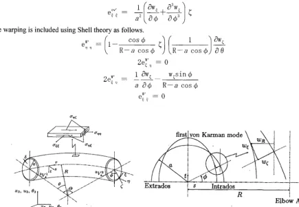
This section explains how the characteristics of the pipe element are formulated. In this study, we used the four-node isoparametric pipe element developed by [3]-[6]. In addition to the beam deformation, this element can analyze ovalization and warping effects based on pipe cross-section deformation. Its basic assumptions of this element are as follows:
(1)The plane normal to the central axis remains flat although it is no longer normal to the axis after the deformation.
(2)The circumferential strain e ¢ ¢ is zero at mid points between the inner and outer radii and the ~ ~"-plane is under a plane stress condition.
And the pipe-beam formulation of this element takes geometric nonlinearity into consideration. It is assumed that the additional stresses based on pipe-beam and cross-section deformation are under plain stress condition. For ovalization and warping [5 ], the following strains are employed.
0 2 0
Here, in actual analysis, ~ is approximated into based on the assumption of a completely round cross-section ® 0 r
shape of pipe element. And L denotes a length of a pipe element. In addition, in case of both ovalization and warping deformation of the straight pipe element, R ~ e o is assumed in the ovalization and warping formulation (7)-(14).
• The ovalization is included by using the von Karman ovalization modes with
W7 ~ - - n
O4) and
eOV _ w~s]n 4) + (3w~ cos ¢ - 1 c~2w~
- - a cos@ 8 ~ R - - a c o s ~ 802
2e°V'= 1 Ow e
" "~ R - - a cos 0 (3 0
(7)
(8)
ov,
__1 (o%v~ + c~aw~ 1
e ~ , - a~ 04) c~4) a The warping is included using Shell theory as follows." R a cos 4)
--
R a cos 4)--
c~0
2e~',, -- 01 Ow e w~sin 4) 2 e ~ ' -- - - -
a c~ 4) R-- a cos 4) IV' - - 0
e ~
(10)
(11)
(12) (13) (14)
on¢
"\" I" I X3, ~3, 03[ - " ~ . i " "
] ..1 i x . , ,
I , I
X2, U2, 02
~ K
arman mode~
i i
i
i i ; i i
m.
Extrados ! s Intrados i
r . . .
, I
I
R
;
Elbow Axis
Figure. 1 Coordinate system and displacement of pipe element
F O R M U L A T I O N OF THE D Y N A M I C C O M B I N A T I O N A N A L Y S I S
The dynamic virtual work equation of rate form due to the updated Lagrangian method with a constraint condition X (t'u) = 0 at time t' - (t + A t) based upon the penalty method is given by equation (15). We added the potentials of the imaginary springs as the penalty method to this dynamic virtual work equation. This means that the displacements of adjacent elements can be made to match at the connection points, and changes in cross-sectional shape are transferred across the connections. Since pipe elements and elasto-plastic solid elements have different degrees of freedom, we used coordinate conversion to convert all the motions of the pipe elements into displacements alone for the solid elements, as shown below.
Iv t' ot, ii" 6 u d v + I~ t ' s " 6~'Edv-- t
Is
t' i" " 6 uds --i
P t g " 6 udv ÷f
a 2; " 6 X d ~ -- 0 (15)Here, U and V show the joint displacement of a solid element and the degree of freedom (of joint) of pipe element, o t', tt' S ,
" ' t'
t ' E t ' t and p t g s h o w the mass density, the relative second Piola-Kirchhoff stress, the relative Green-Lagrange strain,
t ' '
the surface force, and the body force; c~ shows the penalty parameter and ~ is the domain in which the constraint condition is given. Provided that matrix G is assumed as the transformation from V to U (U (or U2)and V (or V2) denote the joint displacement of a solid element and the degree of freedom (of joint) of pipe element), the constraint condition is given by
X = t ' U 2 - G t ' V 2 ( 1 6 )
solid e l e m e n t UI
piPe e l e m e n t £2 U2 U2 p i p e e~lement Figure 2. Pipe-solid combination model.
A N A L Y S I S E X A M P L E S
A N A L Y S I S M O D E L
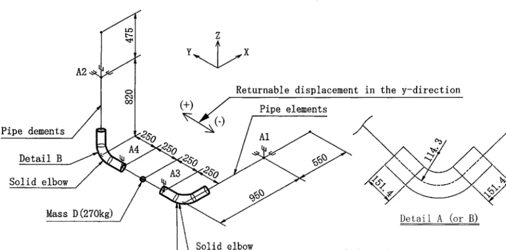
The analysis model, as shown in Figure 3, assumes pipes with a diameter of 89.1 mm and thickness of 5.5mm with two elbow fittings, where ratcheting is expected to occur. Therefore, in this analysis, taking into consideration the effects of the plastic deformation based on ratcheting, these elbow fittings and the pipe areas connected at both their ends are modeled by the elasto-plastic 3D solid finite elements and the other parts are modeled by the pipe finite elements. Also connected are three-axis rotation-flee supports (the other degrees of freedom are restricted) at the locations shown by A~ and A 2 and z-axis displacement-fixing supports (the other degrees of freedom are flee) at the locations shown by As and A4. A mass of 270 kg is added to the point D. And an internal pressure to produce stress equivalent to the deviation stress Sm which is defined in ASME SectionllI is applied to the solid elements and the pipe elements.
In this analysis, we assume seamless piping made of carbon steel seamless pipe. This analysis employs the kinematics hardening law including the parameters C 1=2000 and C2=25 of nonlinear Ziegler evolution law as the material characteristic, yield stress is 294 N/mm 2, and young modulus E = 203000 N/mm 2. A Poisson ratio of 0.3 is employed. The input material stress-strain curve is assumed as shown in Figure 4. We employ the input seismic wave shown in Figure 5 for this dynamic analysis. This wave is multiplied as five times of the design seismic wave that is caused by the extreme design earthquake at the operation floor level of a reactor building in a nuclear power plant through the seismic structural analysis.
A2
Pipe dements
D e t a i l B Solid elbow
Mass D
g)
-)
R e t u r n a b l e d i s p l a c e m e n t in the Y - d i r e c t i o n Pipe elements
A1
Detail A (or B) S~_~id elbow
Detail A (unit • mm)
9 0 0 . . . 8 0 800
700 600 500 400 300 200 100
J
J
J
r~ 402o
. o 0
,-~ 20
o
¢~ 40 -60
o -80 L _ _
0 0.01 0.02 0.03 0.04 0 05 0 5 10 15 20 25 30 35
strain (-) time (sec)
40 45
Figure 4. Input material characteristic. Figure 5. Input seismic wave.
In addition, the time step of this dynamic analysis is A t = 0.002 sec. The Newmark-/3 method (/3 = 0.3025, ~" = 0.6) is used during the time integration, and there is no repetition calculation. The conventional Euler method is used for the stress integration in the elasto-plastic analysis. Only a numerical damping is hypothesized for the solid elements.
A N A L Y S I S R E S U L T S
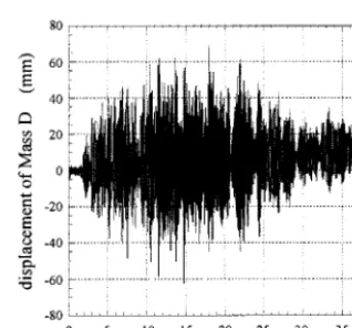
In case of the analysis model shown in Figure 3, the maximum Y-direction displacement at the mass D is solved in this analysis. We show the acceleration and displacement histories in the y-direction at the center of mass D as shown in Figure 6 and 7. Especially, the progression of displacement history for (+) side direction shown in Figure 3 is observed in this analysis result.
200 -
150
100
5o
o
0
o ~- -50
o -100
time (sec)
-150
0 5 10 15 20 25 30 35 40
8 0 , . . . . i . . . .
"~" 60
g
40
20 0 0
-20
¢)
E
o - 4 0 r ~
;.~ -60 !
I . . .
i i . . . . i
-8o . . . . i . . . i . . .
0 5 10 15 20 25 30 35 40
time (sec)
Figure 6. Acceleration history at the center of mass D. Figure 7. Displacement history at the center of mass D.
Figure 8 shows the reference part of the circumferential strain history. Figure 9 shows the circumferential strain history of the analysis at the reference point (the flank of elbow fitting A) with nonlinear Ziegler evolution law. In this analysis, the strain is gradually and linearly progressing until at = around 15 sec. However, the strain progression reduces gradually since t = around 15.0 sec and begins to be saturated since t = around 25.0 sec, including little reduction. According to these analysis results shown in Figure 9, the amplitude of the strain history is around 0.2 % and the level of strain progression reaches around 4 % at t = around 20 sec.
In the shaking test [2], the crack penetration was experientially observed at the flank of an elbow fitting, where the strain progression reached the level of around 4 %, including the strain amplitude of around 1.5 %. On the amplitude of the strain history, this analysis result is smaller than the test result. And on the level of strain progression, this analysis result is the approximately same as the test result from around 20 sec to around 40 sec.
In accordance with the premises of this analysis, the input wave is multiplied as five times of the seismic wave that is caused by the extreme design earthquake at the operation floor level of a reactor building in a nuclear power plant through the seismic structural analysis. For this reason, the strain progression level and strain amplitude under the seismic wave, as
the fifth of this input wave, may be smaller than the results of this analysis and the other shaking test.
Reference Part 0.05
/ ~ f o r the circumferential ,7- 0.04 Top ~ 0.03
~
~
o
.~
o.0~E
q'~ 0.01 °
• ~- 0
~'~-'- C C-...~C o , ~ B 27 ottom -001
............... ~ t=20.0s~~
t=5.
time (sec)
315 4o
Figure 8. Detail A shown in Figure 3 Figure 9. Strain histories at the side of elbow fitting A in the circumferential direction.
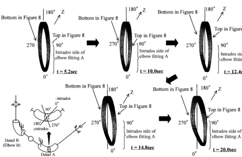
Figure 10 shows the cross-section deformation in an axial direction ( warping ) at the center cross-section of elbow fitting A. And Figure 11 shows the cross-section deformation in a radius direction ( ovalization ) at the center cross-section of elbow fitting A.
Until t = around 10.0 sec, it is demonstrated that the ovalization of cross-section is regularly deforming with warping as shown in Figure 10. In accordance with the reduction of input acceleration, the warping reduces gradually at the intrados cross-section of elbow fitting A. And, in this analysis, the increase and decrease of warping is influenced by the piping response behavior.
However, from t = around 15 sec, in accordance with the reduction of input acceleration amplitude shown in Figure 5, the cross-section shape is hardly remained as its initial shape of cross-section as shown in Figure 10.
Bottom in Figure 8
270
180 ° 180° Z
I
O 0
Z
I Bottom in Figu
Top in Figure 8
f
270 °] 90°
|Intrados side of I elbow fitting A
) t = 5 . 2 s e c
Bottom in Figure "intrados
0 o 90 °
270 °
Detail B (Elbow B)
Detail A (Elbow A) Reference part
Bottom in Fig
0
Top in Figure 8
/./t90° Intrados side of I ~ elbow fitting A
t = l O . O s e c
Z
!
Top in Figure 8
f
Bottom in Figure 270 °
" 9 0 "
Intrados side of elbow fitting A
t = 14.8sec
270 °
0 0
180 ° Z
!
Top in Figure 8
Y
t
90
Intrados side of elbow fitting A
t = 12.4see
Z
I
p in Figure 8
p0 °
ntrados side of ,qbow fitting A
t = 2 0 . 0 s e e
Figure 10. Cross-section deformation (warping) of elbow fitting A.
Top in Figure 8
9 0 o , ~ / /
180 ° 0 °
Bottom in Figure 8 270 ° Intrados side of
elbow fitting A
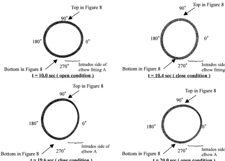
t = 10.0 sec ( o p e n c o n d i t i o n )
Top in Figure 8
90 ° ~ / /
180 ° 0 °
Intrados side of
Bottom in Figure 8 270° elbow A
t = 19.6 see ( close condition )
9 0 ~ / / T o p in Figure 8
180° i I
0
270 ° Bottom in Figure 8 /
t = 10.4 s e c ( c l o s e c o n d i t i o n )
Intrados side of elbow fitting A
Top in Figure 8
90 ° ~ /
180 ° 10 °
Bottom in Figure 8 270° elbowIntrad°SA side of
t = 20.0 sec ( o p e n c o n d i t i o n )
Figure 11. Cross-section deformation (ovalization) of elbow fitting A.
Figure 12 shows the diameter deformation histories of 0 ° -180 ° and 90 ° -270 ° locations at the cross-section of elbow fitting A. In this analysis, it is demonstrated that both 0 ° -180 ° and 90 ° -270 ° diameters histories of elbow fitting A are progressing in the direction of making these diameters expand until t - around 20 s. However, from t - around 20 s, it demonstrated that the 90 ° -270 ° diameter progression is under reduction.
9 5 ~ . . . . ~ . . . . ~ . . . . ~ . . . ~ . . .
i. ... 1 ~ ... i ... i ... i ...
"~'~ 9394-.iii-. .. . . ii~iiii.i iili i ... ti...i... !...t!11 ... ~ ;.-i .... ... i
f
o ... , - ~ ! ~ i i , ,-ii ... ,~ ... , ~ , , ~
90
iit
... 1 ~ _ ~ ... i ... i ...° ...
.... ...
... i i i
I
0 5 10 15 20 25 30 35 40
time (sec)
0 ° -180 ° d i a m e t e r h i s t o r y
94~
93! ... i ... ~ ... i ... !i ... ~ ... i ... ! ... i
91 . . .
°
9 o ~ ... il ...I ji~ ilr L!!i ~,tt~l i,~ !~l;~=i i J !~ .... i
l i i i~, -... i i ! ... ... i
87
0 5 10 15 20 25 30 35 40
time (sec)
90 ° -270 ° d i a m e t e r h i s t o r y
Figure 12. Diameter deformation histories at elbow fitting A
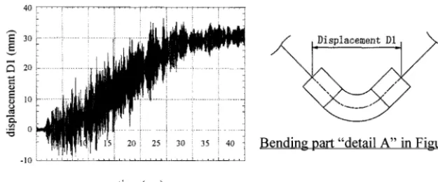
And the displacement history between the ends of a solid bending pipe area A are shown in Figure 13. The progression
of displacement history for an open side direction is observed in this analysis.
4 0 i . . . ! . . . . I . . . . i ........
~ 2 o ~ F i .
o
0 .... i ...
20 25 30 35 Bending part "detail A" in Figure 3
t i m e ( s e c )
Figure 13. Displacement history between the ends of a solid bending pipe area A
C O N C L U S I O N
We performed the elasto-plastic and dynamic analysis of the piping system under the input seismic wave with the elasto- plastic FE analysis program [ 1 ]. This wave was multiplied as five times of the seismic wave that was caused by the extreme design earthquake at the operation floor level of a reactor building in a nuclear power plant through the seismic structural analysis.
In this analysis, we investigated the elasto-plastic deformation of a piping system. Through the numerical results, the behavior of strain and cross-section deformation was demonstrated. At the elbow fitting fitting, ratchet is observed due to the response of the piping system under the earthquake wave loading condition. By performing this analysis, we recognized that the elasto-plastic deformation of a piping system was the complex phenomenon, because the deformation and the strain progression are occurred. And taking into consideration the approximate comparison between the test result [2] and these numerical results, we estimated that the strain in the piping system may causes no penetration crack under the extreme design earthquake.
R E F E R E N C E S
1. Nobuyoshi Iriki, Toshiaki Hisada, Hiroshi Watanabe, Tetsundo Nakatogawa, and Koichiro Oketani, Ratchet Analysis of Piping Systems by Dynamic Elasto-plastic FEM, SMiRT-15, K12/4, IX-153, 1999
2. K. Yoshino, R. Endou, T. Sakakida, H. Yokota, T. Fujwaka, Y. Asada, and K. Suzuki, study on Seismic Design of Nuclear Power Plant piping in Japan : Part3-Componemt Test Results, PVP-Vol.407, 131-137, 2000.
3.Bathe, K. J. and Almedia, C. A., ASME J. Appl. Mech, Vol. 47, 93, 1980. 4. Bathe, K. J. and Almedia, C. A., ibid, Vol. 49, 165, 1982.
5. Bathe, K. J. and Almedia, C. A., ibid, Vol. 49, 914, 1982.
6. Bathe, K. J., Almedia, C. A. and Ho, L. W., Comput. Struct., Vol. 17, 659, 1983. 7. ADINA R&D, Inc., The ADINA Pipe Elements Report ARD 91-16, October 1991. 8. Benson, D. J. and Hallquist, J. O., Int. J. Num. Meth. Eng., Vol. 12, 723, 1986. 9. Park, K. C. and Saczalski, K. J., Trans. ASME, J. Eng. Ind., Vol. 96, 1041, 1974.
10. Tong, P. and Rossetos, J. N., Comput. Struct., Vol. 7, 109, 1977.
11. Belytschko, T., Schwer, L. and Klein, M. J., Int. J. Num. Meth. Eng., Vol. 11, 65, 1977. 12. Kleiber, M. and Rojek, J., Proc. Structural Mechanics in Engineering, Vol. 2, 1, 1994. 13. Fujita, Shiraki, Kitade and Nakamura, Kiron, 44-386, 3437, 1978.