Design and Analysis of Low Power Dual Binary ML MAP
Decoder Using VLSI Technology
S.DivyaP 1
PR,R Dr.P.Maniraj KumarP 2
P
P
1
P
PG Scholar, PSNA College of Engg. & Technology, Dindigul, India, 30T[email protected]30T
P
2
P
Professor, Dept.of ECE, PSNA College of Engg. & Technology, Dindigul, India, 30T[email protected]30T
Abstract
Error correction codes are the essential components of the digital communication and data storage system to ensure robust operation of digital applications wherein turbo code is one of the most attractive near optimal error correction codes. Speed is one of the key factors beside the power consumption and area usage for efficient implementation of turbo decoders. In high speed digital communication such as broadband wireless access based on IEEE 802.16e standard and the fourth generation cellular systems, the design of turbo decoder with high throughput is a critical issue. The iterative nature of turbo-decoding algorithms increases their complexity compared to conventional FEC decoding algorithms. So, for real-time implementation of turbo codes, reducing the decoder complexity while preserving bit error- rate (BER) performance is an important design consideration. In this paper, we propose scalable max-log maximum a posteriori algorithm (ML-MAP) processors designs which can support both single-binary (SB) and dual binary (DB) CTC decoding.
Keywords:Convolutional Encoder, Maximum A Posteriori (MAP) Decoder, Turbo Decoder,ML-MAP Decoder.
1.Introduction
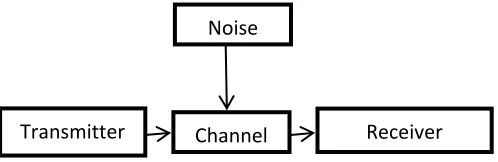
With rapid growth of multimedia services, the convolutional turbo code (CTC) has been widely adopted as one of forward error correcting (FEC) schemes of wireless standards to have a reliable transmission over noisy channels. Single-binary (SB) CTC, proposed in 1993, has been the well-known FEC code that can achieve high data rates and coding gains close to the Shannon limit.
Their decoding complexity was very high for them to be efficiently implemented in hardware when compared with a decoder for convolutional codes like a Viterbi decoder. Demand for turbo codes in wireless communication systems has been increasing since their appearance in the early 1990s, due to their outstanding performance in terms of bit error rate (BER) . In our existing communication systems, reliability of the communication link depends upon block channel codes. To obtain high performance and good quality of service, source data
is encoded into a codeword that adds some redundancy to the transmission of information bits from the source as parity bits. Then, these parity bits are utilized by the decoder at the receiver side to perform forward error correction (FEC).
A Mathematical Theory of Communications, Shannon stated that “a code did exist that could achieve a data rate close to capacity with negligible probability of error”. Turbo code, proposed by Berrou in 1993, shows error correcting performance close to the Shannon limit.
Fig 1:Communication Systems
This turbo code has been used some applications where realtime processing is not required, such as satellite communications, due to its hardware complexity and decoding delay. Since then, a great deal of research effort has been taken to improve the performance of the Turbo code. Recently, high-end portable/mobile devices become prevalent in wireless markets. There are large growing emergence and demands for an inexpensive solution to access the ubiquitous wireless services. Meanwhile, these wireless standards, such as 3GPP and WiMAX standards, adopted CTC schemes with different coding parameters and different throughput rates.
In this paper, we propose a new critical path reduction technique referred to as block-interleaved pipelining (BIP), which Leads to pipelined ACS kernel with less area overhead compared to conventional high - throughput architectures. The MAP algorithm which is used in the turbo decoders is
Transmitter Channel Receiver
Noise
ISSN 2348 – 7968
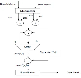
operated in the logarithmic domain in order to reduce the computational complexity. The computation of log likelihood ratio with the values of state metrics is more complicated with log exponential sum calculation. The log exponential sum can be simplified by Jacobian algorithm by adding a correction term along with the max operator. The correction function calculation is critical because of the performance and complexity of the turbo decoder. So a lot of methods are used to simplify the computation to satisfy the performance requirements.
2. Convolutional Encoder
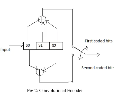
The convolutional encoder maps a continuous information bit stream into a continuous bit stream of encoder output. The convolutional encoder is a finite state machine, which is a machine having memory of past inputs and also having a finite number of different states.
Convolutional codes are commonly specified by three parameters; (n, k, m).
n = number of output bits k = number of input bits
m = number of memory registers Where, n>k
Fig 2: Convolutional Encoder
The quantity k/n is called as code rate. it is a measure of the efficiency of the code . The quantity L is called the constraint length of the code and is defined by Constraint Length, L = k (m-1).The constraint length L represents the number of bits in the encoder memory that affect the generation of the n output bits. The constraint length L is also referred to by the capital letter K, which can be confusing with the lower case k, which represents the number of input bits.
3. Turbo Decoding
Turbo decoding is based on the principle of comparing the probability of a received soft input data being a ‘1’ and ‘0’. The Turbo Decoder uses a decoding scheme called the MAP (Maximum Aposteriori Probability) algorithm. The algorithm determines the probability of whether each received data symbol is a ‘1’ as well as a ‘0’. This is done with the help of the data, parity symbols, and the decoder knowledge of the encoder trellis. A trellis is a form of a state transition table, of the encoder input/output [4] [5]. Based on the data and parity information, the MAP decoder computes the probability of the encoderbeing in a particular state.
Fig 3: Turbo Decoder
The turbo decoder structure represents two soft-input soft-output (SISO) decoders and one interleaver/deinterleaver between them. Decoding process in a turbo decoder is performed iteratively through the two SISO decoders via the interleaver and the deinterleaver. As shown in Figure 3. When the Max-Log Maximum A Posteriori (MAP) algorithm is applied to each SISO decoder.The Turbo Decoder IP core uses the logarithm of the probability to reduce computation; this is known as Log Likelihood Ratio (LLR).
The computation of the probabilities is done iteratively to obtain a reliable result. Once the result is considered reliable, one can make a final decision as to whether the data symbol is a “1” or “0”.
L (D) = log 𝑃(𝐷=0)𝑃(𝐷=1) (1)
The Log Likelihood Ratio is the probability that the received data bit is a „0‟ divided by the probability that the received data bit is a ‘1’. Thus, taking the logarithm we will have a positive value if P(D=1) > P(D=0), and negative value for the opposite. A positive value means the data value is a “1”, otherwise a “0”. For one complete cycle of
iteration, one needs to compute the LLR using parity for non-interleaved as well as interleaved data.
4. MAP Decoder
Turbo decoders require input soft-output decoding algorithms, among which the maximum a posterior probability (MAP) algorithm is widely adopted for its excellent performance for high throughput; highly parallelized decoder architectures are needed. Turbo-Decoders consist of component decoders which exchange information iteratively. Between iterations, this information is reordered following an interleaving scheme. MAP decoders are superior with respect to communications performance and for that reason preferred in advanced implementations.
5. MLMAP Decoder
The ML-MAP algorithm can be used for reduced complexity decoder implementation [4].The decoding process in MAP algorithm performs calculations of the forward and backward state metric values to obtain the log likelihood ratio (LLR) values, which have the decoded bit information and reliability values.The input sequence consisting of information bits Xk parity bits Yk may includeadditive white Gaussian noise at time k. The MAP decoded output, the log-likelihoodratio of information bits dk can be derived from Equations.
The log likelihood ratio values are calculated by the following equation:
𝐿(𝑑𝑚) = 𝑙𝑛∑∑𝑆𝑚∑∑𝑆𝑚−1𝛾𝛾10(𝑆(𝑆𝑚−1𝑚−1,,𝑆𝑆𝑚𝑚)𝛼(𝑆𝑚−1)𝛽(𝑆𝑚)
𝑆𝑚−1 )𝛼(𝑆𝑚−1)𝛽(𝑆𝑚)
𝑆𝑚 (2)
Forward state metric can be calculated by α(𝑆𝑚) = 𝑙𝑛 ∑𝑆𝑚−1exp (ln 𝛾�𝑆𝑚−1,𝑆𝑚� +
ln 𝛼(𝑆𝑚−1)) (3)
Backward state metric can be calculated by β(𝑆𝑚) = 𝑙𝑛 ∑𝑆𝑚+1exp (ln 𝛾�𝑆𝑚,𝑆𝑚+1� +
ln 𝛽(𝑆𝑚+1)) (4)
where the branch metric (γ) is calculated by the a priori information (Le), channel reliability value (Lc), input symbols (x and y1), the systematic bit (ums) and the parity bit (ump).
Branch metric can be calculated by
γ(𝑆𝑚−1, 𝑆𝑚) = (𝐿𝑒𝑢𝑚𝑠 + 𝐿𝑐𝑥𝑢𝑚𝑠 + 𝐿𝑐𝑦1𝑢𝑚𝑝) (5)
The above equations consists logarithm function. So, it is converted into max log function by the well know approximation, called Jacobi algorithm and which is given below
ln(𝑒𝑥+𝑒𝑦)=max(x,y)+ln(1+𝑒−|𝑥−𝑦|) (6)
6. Metric LLR Calculation
6.1 Pipelined Metric Architecture
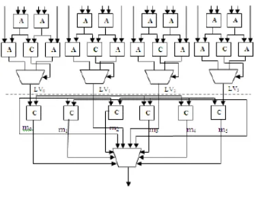
Fig 4:Conventional LLR Unit
In order to compute the LLR values forward (α) and backward (β) states, and branch metric (γ) values of all states are required. Figure shows the conventional architecture of LLR unit[3]. In the conventional architecture, a total of Adders required is 16. A 3-stage compares and select process is used to identifying the max LLR value. This LLR unit can be pipelined in order to reduce the critical path delay.
This proposed architecture consists of three adders, a subtractor, a comparator, one Selection MUX, Trellis MUX and logic. Since, the add-compare select operation is more complex than Trellis MUX, a pipelined architecture is proposed.
ISSN 2348 – 7968
Fig 5: Pipelined Metric Architecture
6.2 Dual Mode Single Binary/Double Binary (SB/DB) MAP Decoding
The radix-4 SB and radix-4 DB MAP is reformulated to achieve high hardware usages and fully-shared storages of the dual mode MAP decoding. In this paper, the shared module design of dual-mode MAP is described in detail. Based on silicon area evaluations, the hardware overhead of dual mode MAP is less than 10% compared with the individual radix-4 SB MAP or individual radix-4 DB MAP.
6.2.1 Radix-4 SB MAP Decoding
The SB CTC encodes one binary bit uk at time k. For decoding two binary bitsat a time, the radix-4 SB ML-MAP algorithm has been derived in by a look-ahead technique. The arithmetic operations of the radix-4 SB ML-MAP are described as follows.
𝛼𝑘(𝑆𝑘) =𝑆𝑘−1,𝑀𝐴𝑋𝑆𝑘−2(𝛾𝑘�𝑆𝑘−2,𝑆𝑘� + 𝛼𝑘−2(𝑆𝑘−2)) (7)
𝛽𝑘(𝑆𝑘) =𝑆𝑀𝐴𝑋
𝑘+1,𝑆𝑘+2�𝛾𝑘+1�𝑆𝑘,𝑆𝑘+2�
+ 𝛽𝑘−2(𝑆𝑘−2)� (8)
𝛾𝑘�𝑆𝑘−2,𝑆𝑘� = Λ𝑎𝑝𝑟,𝑘−1(𝑢𝑘−1) + 𝑦𝑠(𝑘−1)𝑥𝑠(𝑘−1)+
∑ 𝑦𝑚 𝑘−1𝑝𝑖
𝑖=1 𝑥𝑘−1𝑝𝑖 + �Λ𝑎𝑝𝑟,𝑘(𝑢𝑘) + 𝑦𝑠𝑘�𝑥𝑠𝑘+
∑ 𝑦𝑚𝑖=1 𝑝𝑘𝑥𝑝𝑘 (9)
6.2.2 Radix-4 DB MAP Decoding
In DB mode two binary bits are encoded uk=u1k, u2k. The arithmetic operations of the Radix-4 DB MAP are described as,
𝛼𝑘(𝑆𝑘) = 𝑀𝐴𝑋𝑆𝑘−1(𝛾𝑘(𝑆𝑘−1, 𝑆𝑘) + 𝛼𝑘−1(𝑆𝑘−1)) (10)
𝛽𝑘(𝑆𝑘) = 𝑀𝐴𝑋𝑆𝑘+1�𝛾𝑘+1�𝑆𝑘,𝑆𝑘+1� +
𝛽𝑘+1(𝑆𝑘+1)� (11)
𝛾𝑘�𝑆𝑘−1,𝑆𝑘� =Λ(𝑧)𝑎𝑝𝑟,𝑘(𝑢𝑘= 𝑧) + 2𝑦𝑘𝑠1𝑥𝑘𝑠1
+ 2𝑦𝑘𝑠2𝑥𝑘𝑠2+ 2 � 𝑦𝑘𝑝𝑖 𝑚
𝑖=1 𝑥𝑘 𝑝𝑖 (12)
Fig 6: The Block Diagram Of The Dual-Mode MAP Decoder
The “Mode” is used to select the mode of operation.(SB or DB). When “Mode” is active low, the dual-mode LLR calculator is in SB mode. In the dual mode architecture, some of the connections are dummy.
Fig 7: LLR Calculator Of The Dual-Mode SB MAP Decoder
Fig 8: LLR Calculator Of The Dual-Mode DB MAP Decoder
7. Results and Discussion
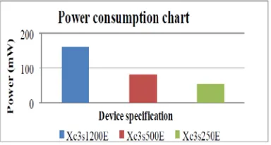
A number of performance evaluation and resource utilization parameters are being used in the design ofpipelined metric MAP decoder. The present research is focused on the design and development of pipelined metric MAP decoder for low power applications. The parameters considered for investigation include number ofslices(S), number of LUTs(Look up table),Slice latches(SL),Occupied Slice latches(OSL) ,IOBs Latches(Input-Output Block),Input IBUFs (Input Buffers),gate counts(GA),Latency(L) and Power consumption(PC).
Fig 9: Comparisons Of Power Consumption
Fig 10: Graphical Representation Of Hardware Utilization
8. Conclusion
The proposed architecture has comparatively simpler code and flexible configuration when compared to other architectures and saves silicon area through efficient device utilization. This work reduces gate count and requires only a one-line buffer memory. Our MAP processor achieved high throughput rates with low energy efficiency and high area efficiency. The Proposed system has minimum number of blocks compared to the conventional System.
References
[1] C. Shannon, “A Mathematical Theory of Information”, Bell System Technical J., vol. 27, July 1948, pp. 379-423.
[2] M. M. Mansour and N. R. Shanbhag, “VLSI architectures for SISO-APP decoders,” IEEE Trans. Very Large Scale Integr. (VLSI) Syst., vol. 11, no. 4, pp. 627–650, Aug. 2003.
[3] S.-J. Lee, N. R. Shanbhag, and A. C. Singer, “Area-efficient highthroughput MAP decoder architectures,” IEEE Trans. Very Large Scale Integr. (VLSI) Syst., vol. 13, no. 8, pp. 921–933, Aug. 2005.
[4] Chen-Hung Lin, Chun-Yu Chen, An-Yeu Wu (Andy),” Area-Efficient Scalable MAP Processor Design for High Throughput Multistandard Convolutional Turbo Decoding” IEEE Transactions on Very Large Scale Integration (VLSI) Systems, Vol. 19, No. 2, February 2011
[5] C. Schurgers, F. Catthoor, and M. Engels, “Memory optimization of MAP turbo decoder algorithms,” IEEE Trans. Very Large Scale Integr.(VLSI) Syst., vol. 9, no. 2, pp. 305–312, Apr. 2001.
ISSN 2348 – 7968
[6] Z.Wang, Z. Chi, and K. K. Parhi, “Area-efficient high-speed decoding schemes for turbo decoders,” IEEE Trans. Very Large Scale Integr.(VLSI) Syst., vol. 10, no. 6, pp. 902–912, Aug. 2002.
[7] S. Shiyamala and V. Rajamani, “A Novel Area Efficient Folded Modified Convolutional Interleaving Architecture for MAP Decoder,” International Journal of Computer Applications, Vol. 9, No. 9, pp-18-22, Nov. 2010.
[8] PerttuSalmela, Harri Sorokin, and JarmoTakala, “A Programmable Max-Log-MAP Turbo Decoder Implementation,” Research Article in VLSI Design, Vol. 2008, 2008.
[9] J. Kaza and C. Chakrabarti, “Design and implementation of low-energy turbo decoders,” IEEE Trans. Very Large Scale Integr. (VLSI) Syst., Vol. 12, no. 9, pp. 968–977, Sep. 2004.
[10] C.-M. Wu, M.-D. Shieh, C.-H.Wu, Y.-T.Hwang, and J.-H. Chen, “VLSI architectural design tradeoffs for sliding-window Log-MAP decoders,”IEEE Trans. Very Large Scale Integr. (VLSI) Syst., Vol. 13, no. 4, pp. 439–447, Apr. 2005.
[11] L. R. Bahl, J. Cocke, F. Jelinek and J. Raviv, “Optimal decoding of linear codes for minimizing
symbol error rate”, IEEE Trans. on Information Theory, pp. 284-287, March 1974.
[12] S. Benedetto, D. Divsalar, G. Montorsi and F. Pollara, “Soft-Output Decoding Algorithms in Iterative Decoding of Turbo Codes”, The Telecommunications and Data Acquisition Progress Report 42-124, Jet Propulsion Laboratory, Pasadena, California, pp. 63-87, February 15, 1996.
[13] Z. Wang, H. Suzuki, and K. K. Parhi, “VLSI Implementation issues of turbo Sdecoder design for wireless applications,” Proc. IEEE Signal Processing Systems (SiPS): Design and Implementation, pp. 503– 512, Oct. 1999.
[14] Cheng-Hung Lin, Chun-Yu Chen, An-Yeu (Andy) Wu, and Tsung- Han Tsai ,”Low-Power Memory-Reduced Traceback MAP Decoding for Double-Binary Convolutional Turbo Decoder”, IEEE Transactions on circuits and systems-I, vol. 56, no. 5, May 2009.
[15] A. J. Viterbi, “An Intuitive Justification and a Simplified Implementation of the MAP Decoder for Convolutional Codes”, IEEE Journal on Selected Areas in Communications, Vol. 16, no. 2, pp. 260-264, February 1998.