Effect of Ground Plane for Enhancing the
Bandwidth and Virtual Size Reduction of
Modified Rectangular Microstrip Antenna
SyedaRafath Ara1, Dr. S. N. Mulgi2
Research Student, Department of Applied Electronics, Gulbarga University, Gulbarga, Karnataka, India1
Professor, Department of Applied Electronics, Gulbarga University, Gulbarga, Karnataka, India2
ABSTRACT: This paper presents the design of a simple rectangular microstrip antenna (RMSA) for wide bandwidth and large virtual size reduction. The conventional RMSA has been modified by using only microstripline feed with reduced substrate area. The modified RMSA gives 3.71% of bandwidth and resonates at 4.59 GHz. This bandwidth has been enhanced to 90.70% with a virtual size reduction of 33.33% by using a ground plane 64.50% smaller than the ground plane used in the modified RMSA. If the ground plane is reduced to 74.50% the antenna gives a highest virtual size reduction of 50%. The enhancement of bandwidth and virtual size reduction are achieved without altering the size of the rectangular patch and nature of broadband radiation characteristics. The proposed antennas are simple in their design and they may find application in WLAN.
KEYWORDS:Modified rectangular microstrip antenna, single microstripline feed, bandwidth, virtual size reduction, WLAN.
I.INTRODUCTION
Today’s wireless communication system requires that an antenna should not only have the wide bandwidth but also a simple structure, compact size, easy integration with the system circuit, stable gain and suitable radiation pattern to cover many applications [1-6]. Microstrip patch antenna is a low profile, light weight, low cost, ease of installation and planar configuration device. But the main drawback is that it shows narrow bandwidth.Many researchers have made an effort to overcome the problem of narrow bandwidth. Various techniques are available in the literature for increasing the bandwidth these include use of different patch configuration, introducing slots on the patch, use of various feeding techniques, use of stacked patches [7-16] etc. In the present scenario the requirement is that, the antenna should have wide bandwidth and compact in size. Because wide bandwidth antennas are more attractive for wireless communication applications. The large ground plane used for the conventional printed antenna is one of the main limitations. Recently the changes in the ground plane have received much attention in improving the antenna parameters. The modified geometry of RMSA and the effect of change in the ground plane of modified RMSA have been reported for wide bandwidth and large virtual size reduction. This kind of study is found to be rare in the literature.
II.ANTENNA STRUCTURE AND DESIGN
The geometries of conventional rectangular microstrip antenna (CRMSA), modified rectangular microstrip antenna (MRMSA) and Antenna-1 are shown in Fig. 1 to 3 respectively. These antennas are located in X-Y plane. As shown in Fig. 1 the CRMSA consists of rectangular geometry patch of length ‘L’ and width ‘W’ fed by using microstripline feed of length ‘Lf’ and width ‘Wf’. The quarter wave transformer of length ‘Lt’ and width ‘Wt’ is used between the patch and
50Ω microstripline feed for matching their impedances. The bottom surface is full copper which is a ground plane. In
Fig. 1 Geometry of CRMSA Fig. 2 Geometry of MRMSA
(a) Top view geometry of Antenna-1 (b) Bottom view geometry of Antenna-1 Fig. 3 Geometry of Antenna-1
The total area of CRMSA is 8 × 8 cm2,MRMSA and Antenna-1 is 6 × 6 cm2. The CRMSA has been designed for 3 GHz on easily available modified glass epoxy substrate material of thickness 0.16 cm with dielectric constant of 4.2.The various antenna parameters of figures 1, 2 and 3 are given in Table-1.
Table-1: Designed parameters of proposed antennas
Parameter in cm L W Lf Wf Lt Wt Ls` Ws`
III.RESULTS AND DISCUSSION
The simulation is carried out by using Ansoft high frequency structure simulation (HFSS) software. The proposed antennas are operates between 1-5 GHz. Figure 4 and 5 shows the variation of return loss versus frequency of CRMSA and MRMSA respectively. From Fig. 4 it is clear that, the CRMSA resonates at 2.66 GHz which is very close to the designed frequency of 3GHz. The antenna resonates between 2.60 to 2.71 GHz and bandwidth is found to be 3.67%. The peak gain of this antenna is found to be 3.66 dB. From Fig. 5 it is clear that, the MRMSA resonates at 4.59 GHz gives 3.71% of bandwidth. The shift in resonance frequency fr from design frequency 3 GHz to 4.59 GHz is due to the
coupling effect of microstripline feed and patch
.
1 2 3 4
-20 -10 0
R
e
tu
rn
L
o
ss
[
d
B
]
Frequency [GHz]
BW1= 3.67%
fr=2.66 GHz
Fig. 4 Return loss versus frequency of CRMSA
3.6 3.8 4.0 4.2 4.4 4.6 4.8 5.0
-20 -18 -16 -14 -12 -10 -8 -6 -4 -2 0
R
e
tu
r
n
L
o
ss
[
d
B
]
Frequency [GHz] BW2=3.71%
fr=4.59 GHz
Fig. 5 Return loss verses frequency ofMRMSA
1 2 3 4 -40 -35 -30 -25 -20 -15 -10 -5 0 R et u r n L o ss [ d B ] Frequency [GHz] Lg=2.13cm Lg=1.93cm Lg=1..73cm Lg=1..53cm f1 f2 f3 f4 f1=3.01 GHz f2=1.65 GHz f3=1.51 GHz f4=1.38 GHz BW3=90.70%
Fig. 6 Variation of return loss versus frequency of Antenna-1 when Lg=2.13, 1.93, 1.73, 1.53 cm
When size of the ground plane is varied to 1.93, 1.73 and 1.53 cm the obtained virtual size reduction, bandwidth and gain is given in the Table-2. From this table it is clear that, the maximum virtual size reduction of 50% is achieved when size of ground plane is kept at 1.53 cm. However the gain of the antenna is maximum (3.56 dB) when Lg is 1.73cm but in this case the antenna gives marginally lesser bandwidth which is 34.5%. Hence Lg is the parameter and may be varied to control bandwidth, virtual size reduction and gain of the antenna. Figure 7 (a) and (b) shows the variation of bandwidth and virtual size reduction with respect to change in the value of Lg.
Table-2: Results for the proposed Antenna-1 for figure 6
Parameter Lg in
cm
Resonance frequency fr in
GHz
Return Loss in dB
B.W. in %
Virtual Size Reduction in %
Gain in dB
1.53 1.38 -15 35.2 50.00 3.09
1.73 1.51 -22 34.5 47.30 3.56
1.93 1.65 -28 49.4 42.62 3.26
2.13 3.01
1.96
-50 90.7 33.33 2.17
1.4 1.6 1.8 2.0 2.2 2.4
30 40 50 60 70 80 90 100 B a n d w id th i n %
Lg in cm
1.5 1.6 1.7 1.8 1.9 2.0 2.1 2.2 30 40 50 V ir tu a l S iz e R e d u c ti o n i n %
Lg in cm
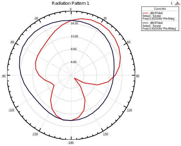
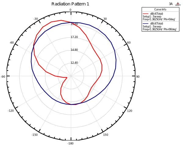
The radiation characteristics of CRMSA, MRMSA and Antenna-1 are also studied. The typical E and H-plane radiation patterns of the proposed antennas are illustrated in Fig. 8 to 10 measured at their resonant frequency. From Fig. 8 to 13 it is clear that, the patterns are broadsides and linearly polarised.
Fig. 8 Typical radiation pattern for E and H-plane of CRMSA measured at 2.66 GHz
Fig. 9 Typical radiation pattern for E and H-plane of MRMSA measured at 4.59 GHz
-20.00 -10.00 0.00 10.00
90 60 30
0
-30
-60
-90
-120
-150
-180
150
120
786-4
Radiation Pattern 2 ANSOFT
Curve Inf o dB(rETotal) Setup1 : Sw eep Freq='4.5775GHz' Phi='0deg'
Fig. 10 Typical radiation pattern for E and H-plane of Antenna-1 measured at 3.01 GHz
Fig. 11 Typical radiation pattern for E and H-plane of Antenna-1 measured at 1.65 GHz
6.00 9.50 13.00 16.50
90 60 30
0
-30
-60
-90
-120
-150
-180
150
120
1
Radiation Pattern 1 ANSOFT
Curve Inf o dB(rETotal) Setup1 : Sw eep Freq='1.6525GHz' Phi='0deg'
dB(rETotal) Setup1 : Sw eep Freq='1.6525GHz' Phi='90deg' -19.00
-13.00 -7.00 -1.00
90 60 30
0
-30
-60
-90
-120
-150
-180
150
120
786-5
Radiation Pattern 1 ANSOFT
Curve Info dB(GainTotal) Setup2 : Sw eep Freq='3.01GHz' Phi='0deg'
Fig. 12 Typical radiation pattern for E and H-plane of Antenna-1 measured at 1.51 GHz
Fig. 13 Typical radiation pattern for E and H-plane of Antenna-1 measured at 1.38 GHz
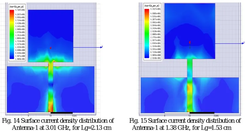
Since Antenna-1 gives highest bandwidth of 90.70% with a virtual size reduction of 33.33% when Lg=2.13 cm. Its current distribution is shown in Fig. 14. The Antenna-1 gives the highest virtual size reduction of 50% when Lg=1.53 cm. Its current distribution is shown in Fig. 15. From these two figures it is clear that, the current is mainly concentrated on the top and bottom portion of the patch with very low density at the centre and it is distributed along the edges of the patch indicates wide band operation
.
6.50 10.50 14.50 18.50
90 60 30
0
-30
-60
-90
-120
-150
-180
150
120
2
Radiation Pattern 1 ANSOFT
Curve Inf o dB(rETotal) Setup1 : Sw eep Freq='1.5175GHz' Phi='0deg'
dB(rETotal) Setup1 : Sw eep Freq='1.5175GHz' Phi='90deg'
12.40 14.80 17.20 19.60
90 60 30
0
-30
-60
-90
-120
-150
-180
150
120
3A
Radiation Pattern 1 ANSOFT
Curve Inf o dB(rETotal) Setup1 : Sw eep Freq='1.3825GHz' Phi='0deg'
Fig. 14 Surface current density distribution of Fig. 15 Surface current density distribution of Antenna-1 at 3.01 GHz, for Lg=2.13 cm Antenna-1 at 1.38 GHz, for Lg=1.53 cm
IV.CONCLUSION
From the detailed study it is found that, the bandwidth and virtual size reduction can be enhanced without any modification of the rectangular patch. The CRMSA is simplified by using single microstripline feed. The technique used in this study is found to be more simple and easy. The 25% smaller substrate area compare to the substrate area of CRMSA are used for the construction of MRMSA gives 3.71% of bandwidth. This bandwidth has been enhanced to 90.70% with a virtual size reduction of 33.33% by using 64.5% smaller ground plane compare to the ground plane used for MRMSA. Further highest virtual size reduction of 50% is obtained by using 74.5% smaller ground plane compare to ground plane of MRMSA. The reduction of ground plane also enhances the gain of CRMSA from 2.17 to 3.56 dB. The enhancement of bandwidth, virtual size reduction and gain does not affect much the nature of broad band characteristics. The proposed antennas may find application in WLAN.
REFERENCES
[1] Constantine A. Balanis, “Antenna Theory - Analysis and Design,” John Wiley & Sons, Inc., New York, 1982.
[2] David M. Pozar and Daniel H.Schaubert, “Microstrip Antennas: The Analysis and Design of Microstrip Antennas and Arrays,” IEEE,
Antennas and Propagation Society, Sponsor, IEEE Press, Inc., New York, 1995.
[3] I. J. Bhal and P. Bhartia, “Microstrip Antennas,” Dedham, MA: Artech House, 1981.
[4] G. A. Deschamps, “Microstrip microwave antennas,” Presented at the 3rd USAF, Symposium on Antennas, 1953.
[5] Girish Kumar and K. P. Ray, “Broadband Microstrip Antennas,” Norwood, MA: Artech House, 2003.
[6] Kai-Fong Lee and Wei Chen, “Advances in Microstrip and Printed Antennas,” Wiley-Interscience Publication, John Wiley & Sons, INC. New
York 1997.
[7] L.Liu, S.W. Cheung, and T.I. Yuk, “Bandwidth improvement using Ground slots compact UWB Microstrip-fed Antennas,” PIERS
Proceedings, Suzhou, China, September 12-16, 2011.
[8] D. M. Pozar and B. Kaufman, “Increasing bandwidth of a microstrip antenna by proximity coupling,” Elect. Lett, vol. 23, no. 8, pp. 368-369,
Apr. 1987.
[9] Frank Zavosh and James T. Aberle, “Improving the performance of microstrip-patch antennas,” IEEE, Trans. Antennas Propagat. Magz, vol.
38, pp. 7-11, Aug. 1996.
[10] Jia Yi Sze and Kin Lu Wong, “Slotted rectangular microstrip antenna for bandwidth enhancement,” IEEE, Trans. Antennas Propag., vol. 48,
no. 8, pp. 1149-1152, Aug. 2000.
[11] Jen-Yea Jan andJia-Wei Su, “Bandwidth enhancement of a printed wide slot antenna with a rotated slot,” IEEE, Trans. Antennas Propag.,vol.
53, no. 6, pp. 2111-2114, Jun. 2005.
[12] Zhu Qi and Bao Liang, “Design of microstrip antenna with broader bandwidth and beam,” IEEE, Antennas Propag., Soc., Inter. National
Symp., vol. 3A, pp. 617-620, Jul. 2005.
[13] AlbertSabban, “A new broadband stacked two-layer microstrip antenna,” IEEE, AP-S, Int. Symp. Dig., pp. 63-66, 1983.
[14] H. C. Go and Y. W Jang, "Multi-band modified fork-shaped antenna with ground plane including dual-triangle microstrip monopole portion,
Electron. Lett.,” vo1.40, no.10,May. 2004.
[15] Gwo- yun Lee and Kin-Lu Wong, "Very- Iow-profile bent planar monopole antenna for GSM/DCS dual-band mobile phone," Microwave Opt.
[16] Wang-Sang Lee, Dong- Zo Kim, Ki-Jin Kim, and Jong-Won Yu Member, IEEE, “Wideband Planar Monopole Antennas With Dual Band- Notched Characteristics,” IEEE Transactions on Microwave theory and techniques, vol. 54, no. 6, jun. 2006.
BIOGRAPHY
SyedaRafathAra has pursued her Master’s degree and Master of Philosophy degree in Applied Electronics from Gulbarga University, Gulbarga in the year 1994 and 1997. Currently she is working as an Assistant Professor in the Department of Electronics, Govt. First grade College, Gulbarga, Karnataka State, India. Her area of research includes Microwave electronics. She is pursuing Ph.D. in Applied Electronics under the guidance of Dr. S.N. Mulgi, Professor of Applied Electronics, Gulbarga University, Gulbarga.