Mathematical modeling of transformable space
structure dynamics
Vladimir Zimin1,*, Alexey Krylov1, Sergey Churilin1, and Zikun Zhang1
1Bauman Moscow State Technical University, 2-nd Baumanskaya str., 5, building 1, 105005
Moscow, Russia
Abstract. Today large space structures are in focus of attention of engineers and designers of rocket and space equipment. In ground-based experiments, it is not always possible to carry out complex tests of large space structure functionality. Therefore, the development of mathematical models describing properly the transformable structure dynamics when they opened from the densely packed transport state to the operating position in the orbit becomes very important. To determine the stress-strain state of the frame elements when it is unfolding the shape of the framework is taken at the moments when relative velocities of the adjacent sections are maximal. Supposed, that at these moments the frame elements are getting on the stops limiting their relative angular displacements, and the structure behaves as an elastic rod with specified characteristics. Numerical analysis of the stress-strain state in the framework is carried out by means of a finite element model. Therefore, the represented mathematical model can be effectively used to predict the functional suitability of such transformable space structures already on the early stages of their development.
1 Introduction
Among the large space structures a special place is occupied by transformable structures allowing configuration changes [1-4]. Such structures are delivered to a near-earth orbit being folded and placed in a container. As a rule, the size of the container is very limited and it is impossible to place inside it large elements forming the main part of the load-bearing framework of large space systems. When the desired operational orbit is reached, the opening of the structure load-bearing framework (or its transformation) is fulfilled. Dimensions of the framework in the transport (folded) state can differ ten times from its dimensions in the unfolded operating state. Therefore, the design of the load-bearing framework for the transformable space systems contains a large number of elements connected by hinges. Usually at the end of the opening the framework elements are getting stand on the locks, i.e. they are rigidly fixed at the end of frame transformation. However, for some structures, stops providing the required shape of a load-bearing framework in the operating position can be used instead of the locks. Deployment of the transformable structure is executed by power drives that can be compressed or stretched springs, electric
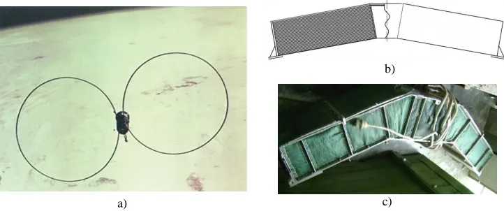
motors, drives made of materials with shape memory effect, etc. From currently developed transformable space systems, the simplest one is a flat multi-link structure made of one-type elements (Fig. 1).
a)
b)
c)
Fig. 1. Transformable space structure: a) spacecraft with two closed load-bearing framework; b) the load-bearing framework put into the container; c) external view of the container.
It should be noted that during the ground tests of deployment of the transformable space systems, it is impossible to repeat fully the orbital conditions of the deployment and to confirm the reliability and efficiency of the developed structures. At development time, correctness of technical solutions incorporated in a transformable structure can be estimated by means of the mathematical modeling of its unfolding stages. The numerical modeling makes it possible to consider various schemes of laying and opening, to reveal their advantages and disadvantages. Therefore, at the beginning steps of the development, generation of mathematical models that ensure effective calculation of the structural parameters and analysis of various variants of packing the structure for transportation and subsequent unfolding to the operating position in the orbit is an urgent task.
2 The mathematical model
To study the deployment dynamics of a multi-link load-bearing framework, a simple but good enough considering the structural features calculation scheme is adopted. It is a system of absolutely rigid bodies connected to each other by hinges. Masses and moments of inertia of these rigid bodies are taken equal to the masses and moments of inertia of the real framework elements. Equations of the framework motion in general form can be written as Lagrange equations of the second kind
, 1, 2,..., i
i i
d T T
Q i n
dt
, (1)
where T – kinetic energy of the system; i – generalized angular coordinates; i – generalized angular velocities; Qi – generalized forces; n – number of generalized coordinates.
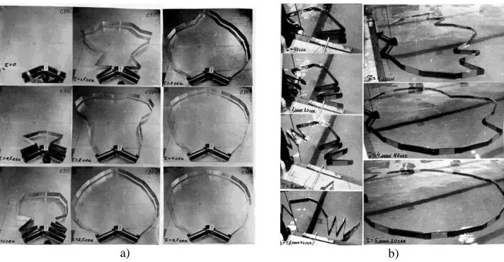
Torsion springs located in the hinges are modeled by a mass-less elastic and damping elements. When unfolding, the adjacent elements of the load-bearing frame can move towards each other and touch each other. To model such behavior the mass-less elastic elements with nonlinear dependence of the moment on the opening angle are used. Parameters of such mass-less elastic and damping elements modeling stops and holders were determined experimentally. For this purpose, experiments on the unfolding of the load-bearing framework with a diameter of 5 m assembled from elements of the real structure with a diameter of 20 m were carried out. From analysis and comparison of calculations and experimental data, characteristics of the mass-less elastic and damping elements modeling the stops were obtained (Fig. 2).
a) b)
Fig. 2. On-earth experimental tests on the adjustment of the framework unfolding: a) on a flat surface; b) in a pool
Operability of the transformable structure depends on the magnitude of the efforts arising in it when it is unfolding from the densely packed state to the operating position in orbit. The stress-strain state of elements of the transformable load-bearing framework during its opening is determined by the impact loads that appear when the adjacent structural elements are set on the stops [5]. As a calculation model of the structure the finite element model is accepted
[M]{ ( )} [ ]{ ( )} [ ]{ ( )}u t B u t K u t P( )t , (2)
where [M], [ ]B , [ ]K – mass, damping and stiffness matrices respectively; ( )P t – external
load vector; u( )t , u( )t – vectors of nodal displacements and velocities. In our case
( )t 0
P . When the frame as a system of absolutely rigid bodies is unfolding, velocities at the specified points at certain moments of time are calculated. They are accepted as initial conditions when stresses in the elastic frame are calculated by the finite element method. In this connection, the calculated model of the unfolding is being coordinated with the finite element model of the structure.
3 Results of calculations
and have thickness 0.8 mm (51 panels in each packet). From one side the packets are pivotally connected through a rigid base and from another side – through a short closing panel.
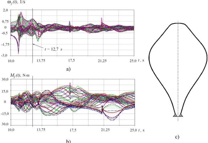
As a result of the numerical analysis of deployment dynamics of the transformable load-bearing frame on the base of the developed model by means of the software package MSC. Adams, coordinates, velocities and accelerations of the panel mass centers as well as their angular velocities and accelerations were obtained. Fulfilled calculations showed that when the framework had been unfolded from transport state to the operating position its elements set themselves on the stops at different moments of time. At each such a moment, the different groups of the elements from the certain frame parts set themselves on the stops. The several moments with maximal relative velocities of the adjacent elements belonging to the considered group were chosen (Fig. 3).
а)
с) b)
Fig. 3.Calculation results: а) the angular velocities of the panels belonging to the left branch of the framework; b) moments acting in the hinge joints when the panels are setting at the stops;
c) the shape of the unfolded framework at t12.7 s.
At each considered moment it was accepted that the hinge joints of the frame adjacent elements were on the stops, and the structure behaved as an elastic rod with specific characteristics. This approach gives the safety margin, since the mobility of the frame elements relative to each other leads to reduction of the real stresses due to the loss of kinetic energy in the joints [6].
Calculated values of velocities in the selected points of the frame model are accepted as initial conditions for calculation of the transient process in the software package MSC.Nastran, that is, when t0 : u( )t 0, u( ) =t u, where u( )t – vector of the nodal
displacements, u0( )t – vector of the initial nodal velocities. Velocity fields for each
а) b) c) d) Fig. 4. The velocity field at the nodes of the finite element model:
а) t 11.0 s; b) t 12.7 s; c) t13.5 s; d) t60.9 s
4 Results discussion
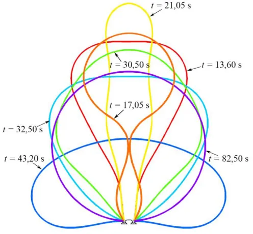
The numerical modeling of the unfolding dynamics of the closed multiple-link load-bearing framework with the diameter of 20 m showed that at certain moments of time approaching of the left and right branches of the structure was possible (Fig. 5).
Fig. 5. Intermediate shapes of unfolding of the closed load-bearing framework
As a result of fulfilled calculations taking into account contact interaction of the frame branches, it was determined the time of setting of the operating position, as well as the structure intermediate shapes during its deploy allowing to estimate the collision of its elements with the spacecraft structural elements. Analysis of the stress-strain state of the frame panels during deployment allows us to ascertain that the dynamic loads do not lead to their destruction during free opening. To avoid contact interaction between the frame elements and the branches of the closed structure, a controlled deployment of this structure instead of its free deployment is required.
When heated, the length of the alloy wire is reduced on 4...7% of the original length and even a thin wire is able to create a rather big force.
5 Conclusion
The developed mathematical model allows us to calculate the unfolding dynamics of the closed multi-link transformable structures and analyze the stress-strain state of their elements during the deployment at early stages of development and creation of unique large systems for operation in space.
References
1. A. V. Lopatin, M. A. Rutkovskaya, Vestnik Sibirskogo gosudarstvennogo aerokosmicheskogo universiteta im. akademika MF Reshetneva (Vestnik SibGAU) 2, 51-57 (2007)
2. S. V. E. Ponomarev, Vestnik Tomskogo gosudarstvennogo universiteta. Matematika i mekhanika 4, 110-119 (2011)
3. J. N. Footdale, J. Banik, In3rd AIAA Spacecraft Structures Conference, 0698 (2016) 4. Im. E. Thomson, M. Fang, H. Pearson, J. Moore, J. Lin, In AIAA SPACE 2007
Conference & Exposition, 9917 (September, 2007).
5. V. N. Zimin, V. E. Meshkovsky, WIT Transactions on Modelling and Simulation, 41
(2005)
6. A.V. Krylov, S.A. Churilin,. Izvestiya vysshikh uchebnykh zavedeniy. Fizika, 56 (7/3), 170-172 (2013)