Volume 2006, Article ID 54868, Pages1–13 DOI 10.1155/ASP/2006/54868
Vienna MIMO Testbed
Sebastian Caban, Christian Mehlf ¨uhrer, Robert Langwieser, Arpad L. Scholtz, and Markus Rupp
Institute of Communications and Radio-Frequency Engineering, Vienna University of Technology, Gusshausstrasse 25/389, 1040 Vienna, Austria
Received 2 December 2004; Revised 20 April 2005; Accepted 4 May 2005
While the field of MIMO transmission has been explored over the past decade mainly theoretically, relatively few results exist on how these transmissions perform over realistic, imperfect channels. The reason for this is that measurement equipment is ex-pensive, difficult to obtain, and often inflexible when a multitude of transmission parameters are of interest. This paper presents a flexible testbed developed to examine MIMO algorithms and channel models described in literature by transmitting data at 2.45 GHz through real, physical channels, supporting simultaneously four transmit and four receive antennas. Operation is per-formed directly from Matlab allowing for a cornucopia of real-world experiments with minimum effort. Examples measuring bit error rates on space-time block codes are provided in the paper.
Copyright © 2006 Sebastian Caban et al. This is an open access article distributed under the Creative Commons Attribution License, which permits unrestricted use, distribution, and reproduction in any medium, provided the original work is properly cited.
1. MOTIVATION
Investigating the performance of highly sophisticated wire-less systems, in particular with multiple transmit and receive antennas, is a difficult task. In most cases, this can only be performed via simulation, which means modeling complex behavior by simpler mathematical descriptions [1]. Matlab simulation [2], with its highly accurate double-precision nu-merical environment, is on the one hand a perfect tool for the investigation of algorithms. On the other hand many imper-fections of thereal-worldare neglected. In particular, fixed-point aspects of future products are often underestimated [3] as well as the true physical behavior of the wireless channel which is quite complex and not too well understood. Follow-ing the concept of simplification, uncertainties in MIMO de-coding algorithms usually do not attract much attention [4]. These uncertainties are mainly simplified assumptions like perfectly known noise levels, additive Gaussian noise, omit-ted synchronization, linear power amplification, and perfect channel knowledge, which often show too optimistic receiver performance in simulation.
1.1. Motivation for rapid prototyping
Prototypes were used in the past to allow for early testing of future products. In particular when new technology was in-volved, such prototyping was a crucial element in the design path for a new product. The advantage of prototyping was
to reduce the investment risk of the new product in case the new technology would hide unforeseen challenges. Also, one often obtained a flavour of how the new technology needs to be realized and a feeling for how the future product would look like. One could thus present it to potential customers, to work with them on particular features, long before the final product was available.
In wireless mobile communications, like personal com-munication, UMTS, WLAN, and so forth, time to market has become a real pressure. Since prototyping is cumbersome work, it is time and cost intensive, and thus a prototype with the above features may cost as much as the final product and may not be available earlier. Due to such reasons, prototyp-ing is nowadays often skipped, buildprototyp-ing products while rely-ingonlyon previous experience and simulation results.
However, experience has shown that such a procedure is quite risky, and a new movement, called rapid prototyping, has been established. In rapid prototyping, not the entire product is built but only the new and risky parts, possibly connected with already existing parts stemming from older products. It is not as thorough as the conventional prototyp-ing approach, but rapid prototypprototyp-ing can prevent high-risk decisions and allows for a first location of challenging areas.
Note that depending on the purpose, different technical terms are being used (see also [5]).
(i) Aprototypeis the initial realization of a research idea or a standard, either as a reference, a proof of concept, or as a vehicle for future development and improvement. (ii) Ademonstratormainly serves as a sales vehicle to show technology to customers. In general it will implement a new idea, concept, or standard that has already been established and has been finalized to some degree. (iii) Atestbed, on the other hand, is generally used for
re-search. It is a vehicle for further development, for ver-ification of algorithms, or ideas under real-world or real-time conditions. This results in the requirement for scalability, modularity, and extendibility.
We will thus refer to our development as testbed, rather than a prototype, throughout this article.
1.2. Motivation for the testbed
A multitude of development kits and prototyping boards are available, in particular supporting fast DSPs (e.g., C6x from TI [6] and SHARK from Analog) as well as FPGAs (e.g., from Xilinx and Altera). However, there are few concepts support-ing multiple DSPs cooperatsupport-ing with multiple FPGAs, as only such a flexibility can support the required complexity in real time. Very few concepts support fast AD and DA converters, as they are required in this field. The next stage in the radio transmission chain requires intermediate-frequency (IF) sig-nal generation. While we found very few companies support-ing this, we did not find any supportsupport-ing radio-frequency (RF) experimental boards. Thus we concluded that we have to at least develop the RF parts on our own, while for most other parts it would be advantageous to use existing platforms. We decided to utilize DSP and FPGA boards from Sundance [7] and IF boards from ICS [8,9].
Once such a flexible and scalable platform is available, only a part of the rapid prototyping environment has been built. A typical user, that is, an algorithmic designer investi-gating coding and decoding schemes, is usually not able to program DSPs and FPGAs due to a lack of time and spe-cialized knowledge. Therefore, he must be able to use such a testbed easily with nearly no effort directly out of an environ-ment he knows well. It is thus advisable to use programming tools like Matlab that can support at least a few DSPs and FPGAs. Although such environments [10,11] exist, they are still not suited to support an algorithmic designer without hardware experience, and they are not able to convert much more than a toy problem into a real-time experiment.
Note however, that many real-time experiments can be performed over a relatively small time period, say several mil-liseconds. In such cases, the complex DSP and FPGA plat-form is not really required. The data sequences can be pre-processed via Matlab and transmitted in burst mode over a real time air interface. Only the capturing of data needs to be performed in real time while the postprocessing can take place later in Matlab. Such operations simply require extensive data storage, which is not much of a cost factor
today. We therefore decided to support scalable and flexible hardware platforms but put emphasis on real-time experi-ments performed directly out of Matlab.
Furthermore, multiuser operation can be quite useful, al-lowing several people to perform different experiments on a single wireless platform. Such feature is supported by a local area network (LAN) interface, allowing people to be distantly located from the measurement equipment.
1.3. Further goals for the testbed
Currently, our research activities using the MIMO testbed are the following.
(i) Investigation and comparison of equalizer structures for the high-speed downlink packet access (HSDPA) mode for UMTS. First results are published in [12]. (ii) Investigation and comparison of corporate proposals
for the MIMO HSDPA mode, which are expected to be standardized in UMTS Release 7.
(iii) Other experiments include channel sounding and channel capacity measurements at 2.45 GHz.
Note that all these experiments are carried out at the same time by different research groups operating the single testbed from their own user PCs. More information on recent results can be obtained from [13].
After presenting the motivation and further goals in Section 1,Section 2provides the details of the testbed con-cept and the realizations of the various subsystems.Section 3 demonstrates first real-time transmissions and shows the measurement results achieved. Section 4finally reports on results when space-time codes are transmitted.
2. MIMO TESTBED DEVELOPMENT
2.1. Existing MIMO testbeds
Starting in 1998 with the first narrowband MIMO prototype [14], several MIMO prototypes were set up in the past to in-vestigate a particular field of interest. This was, for example, MIMO WCDMA transmission for 3G telephone systems (by Lucent Technologies) [15], a MIMO 3G prototype chip de-velopment for high-speed downlink packet access reception (by Lucent Technologies) [16], or MIMO OFDM transmis-sion for 4G telephone systems (by ETRI, Korea) [17]. While these prototypes and testbeds were very expensive, initial re-alizations of a research idea or standards, nowadays mostly testbeds are used in research due to their scalability, modu-larity, and extendibility.
and then transmitted and received to be stored in files and processed by a PC again. Nevertheless, all other testbed de-signs approximately follow the above described structure.
At the University of Duisburg, Germany, a MIMO testbed was set up by utilizing Sundance components for baseband processing and Atmel RF components [20]. At the McGill University, Montreal, Canada, a similar structure is used to create any signal which fits into 3.5 MHz by utilizing ICS boards and extensive hard-disk storage [21]. At the Rice Uni-versity, Houston, Tex, Nallatech FPGA boards are favored for their modular testbed approach [22]. Slightly different, at Young University, Brigham, Utah, USA, data samples are generated in “real-time embedded PCs” plus TI DSPs [23]. At Georgia Tech, Ga, USA, several synchronized Agilent 4438 arbitrary waveform generators are utilized as signal gener-ators for their testbed [24]. To show some more examples, MIMO testbeds are also assembled and operated at RWTH Aachen, Germany [25], at Virginia Tech, USA [26], and at ETH Zurich, Switzerland [27].
2.2. Our MIMO testbed concept
Our testbed resembles the above-mentioned examples and extends them by an easy to use Matlab interface to allow for a multitude of experiments with very different constraints. Our testbed is not developed for a single type of experiment or signal, which means that there is no need to redesign parts of the design or signal processing in order to allow several researchers and research teams to share the same expensive testbed hardware for different experiments. Any transmis-sion can be performed directly out of Matlab from any PC in the local area network (LAN) by utilizing the same conve-nient interface, the Matlab interface. Easy, flexible, and with-out requiring specific hardware knowledge, this platform in-dependent interface leads to reduced development time for a working prototype. Cost for hardware is reduced by sharing the testbed among several research teams.
The developed MIMO testbed [28,29] primarily consists of a PC with transmitter capabilities (transmit PC), channel realizations (in form of emulation or physical channel), a PC with receiver capabilities (receive PC), and one or more user PCs from where the transmit and receive PCs are being op-erated via a LAN connection as depicted inFigure 1.
The various components will be described in more de-tail in the following. Note that this concept allows the al-gorithmic designer to focus on digital baseband data pro-cessing on his ownPC. Via the so-called Matlab interface, the data streams of up to four transmit antennas are sub-mitted to the transmit PC. There, these samples are auto-matically up-converted to the intermediate frequency (IF), transmitted over a radio-frequency (RF) channel, and once they have been captured by the receive PC, they are finally down-converted to the baseband to provide the received raw (unfiltered) baseband data samples. The developed Matlab interface is so flexible that the length of the data stream, the data rate, and the selected IF can be selected from a wide range of parameters, simply handled by setting such param-eters in Matlab.
Matlab interface
LAN
User PCs
Matlab
DSPs + FPGAs See Fig. 10
Transmit PC Server software
Up-converter + DAC See Fig. 2
4x IF
Channel
Fig. 3 4x IF
Receive PC Server software Down-converter + ADC
See Fig. 9
Figure1: Block diagram of the testbed developed.
Complex baseband data samples 2x 14 bits/sample
FIFO polator Inter-4–252
Sin Cos Oscillator 0–100 MHz
+ 14-bit DAC
200 Msamples/s
A
nalog
IF
sig
nal,
F
ig
.3
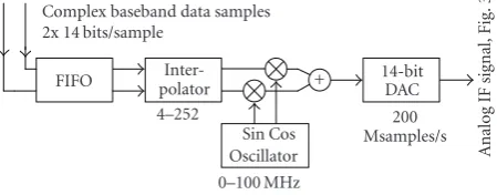
Figure2: Per channel data flow in the transmit PC.
This platform-independent approach allows multiple users to access the testbed directly out of Matlab from any-where in the LAN. This not only makes it very convenient to integrate real-time air transmissions into existing Matlab simulations by the use of a few Matlab commands, but also saves a lot of costs since very expensive hardware can be op-erated efficiently by several researchers simultaneously.1
2.3. The transmit PC
The user, operating the transmit PC directly out of Matlab, provides baseband data samples and a set of options, for ex-ample, the interpolation rate and the desired intermediate frequency. A server software processes these samples and also controls the ICS 564 plugin PCI board [8] which performs the signal conversion to the IF for all four channels as illus-trated inFigure 2.
The incoming samples (up to 50 Msamples/s on up to 4 channels) are buffered by a FIFO (128 ksamples per channel) and then interpolated (user definable between 4 and 252) to reduce the required baseband data rate. Up-conversion to the IF is carried out digitally before conversion to the analog
domain. Utilizing a low IF (user definable between 0 and 100 MHz), rather than baseband signals, avoids the problem of DC offset, carrier leakage, and IQ imbalance while saving half the numbers of DACs.
Furthermore, the Matlab interface allows for various extended options. A user may introduce a delay (user de-finable in milliseconds) between subsequent blocks and/or repeat one or more blocks automatically as desired. This is especially useful if a lot of different channel realizations are of interest.
2.4. The RF channel
The channel setup can either be a physical channel operated via the RF air interface at 2.45 GHz or channel emulators (e.g., Spirent Communications TAS4500 FLEX [30]), allow-ing to repeat experiments with a wide range of channel pa-rameters. The setup ofFigure 3was taken into operation to realize a 4×1 MIMO channel.
The RF front end consists of independent RF transmitters and receivers for each channel with the exception of a com-mon oscillator for all transmitters and receivers. The use of separate modules provides high flexibility for development and testing. Since no restrictions should apply with respect to the modulation scheme, all RF modules were designed to be highly linear. In order to fulfill the requirements for the WLAN standard IEEE 802.11b [31], the modules provide a maximum bandwidth of 20 MHz and about 20 dBm transmit power per channel. Unfortunately, the RF front end cannot be built as flexible as the Matlab interface. We thus had to fix the IF to 70 MHz and RF to 2.45 GHz.
Optionally, additional noise can be added by a UFX-EBNO-IF1 [32] noise source. This is in particular useful when comparing MIMO decoding algorithms for a single user operating at a dedicated SNR level.
2.4.1. Transmit via channel emulators
The usage of two Spirent TAS4500 FLEX channel emula-tors [30] is very beneficial when developing MIMO trans-mission systems. With the channel emulators, a controllable, predictable, and repeatable environment can be set up, al-lowing for various typical channel conditions. The ability to reproduce different measurement scenarios as accurately as possible is of great advantage for algorithmic evaluation and debugging. Furthermore, in this mode there is no need for operating licenses even when operating outside the ISM band because no radiation is emitted.
2.4.2. Transmit via antennas
Since all channel models are based on simplified assump-tions, a transmission via a realistic, physical channel may cover some important and maybe yet unknown aspects which are not taken into consideration by channel emulators. To transmit and receive the RF signal at 2.45 GHz,λ /4-monopoles mounted on a ground plane (seeFigure 4) are used as antennas. They are placed in a uniform linear array
4x RF transmitter
See Fig. 5
Channel emulators
Antennas See Fig. 4
RF receiver See Fig. 6
+ Noise source
70 MHz 2.450 GHz 70 MHz
A
nalog
IF
sig
nal,
F
ig
.9
4x
analog
IF
sig
n
al,
F
ig
.2
Figure3: MIMO channel setup utilizing emulators or the air inter-face.
A
ppr
o
x.
λ/
4
A
ppr
o
x.
λ/
4
(a) (b)
Figure4: Antenna (a) without and (b) with ground plane.
2.380 GHz Common oscillator
To the other channels
A
nalog
IF
sig
nal,
F
ig
.2
IF-to-RF up-converter
RF power amplifier
20 dBm
70 MHz 2.450 GHz
A
nalog
RF
sig
nal
Figure5: RF transmitter block diagram, per channel.
with variable element spacing. The MIMO testbed itself is not limited to this kind of antennas and can support other configurations.
2.4.3. RF transmitter
IF-to-RF up-converter
Since the IF output of the transmit PC is not filtered, higher harmonic frequencies are also created by the digital-to-analog conversion in addition to the desired IF signal. In the up-converter, at first this 70 MHz IF signal is filtered by us-ing a low-loss surface acoustic wave (SAW) filter with a 3 dB bandwidth of 20 MHz. In order to reduce out-of-band reflec-tions distorting the DAC operareflec-tions, an isolating attenuator is placed in front of the IF filter. The up-conversion from the IF to the RF is performed in one step by a double-balanced mixer. This mixer is followed by an amplifier and an RF bandpass filter to create an output signal with enough signal level to drive the channel emulators. The up-converter mod-ule is operated on a single 3 V voltage supply and a−15 dBm signal from the common oscillator.
RF power amplifier
Amplification to the transmit power level of 20 dBm is car-ried out in two stages, with RF bandpass filters placed in between. The power consumption of the power amplifier is about 2 W and it is operated on a single 5 V voltage supply.
2.4.4. RF receiver
The RF receiver consists of three modules for each channel: a low-noise amplifier (LNA), an RF-to-IF down-converter, and a gain-controlled amplifier (GCA). The common oscillator can be used by up to four down-converters.Figure 6shows the RF receiver block diagram.
Low-noise amplifier
At the input of the low-noise amplifier module, a receive fil-ter is needed to protect the following low-noise transistor from blocking because of many other radio applications in the 2.4 GHz ISM band and the nearby UMTS band. A second filter after the LNA is used to additionally suppress image fre-quency signals. This filter is followed by an amplifying buffer.
RF-to-IF down-converter
Down-conversion to IF is performed by a double-balanced mixer, using a common oscillator signal with a power level of
−10 dBm. A low-loss SAW IF filter follows to limit the noise bandwidth of the RF system to 20 MHz and to filter unde-sired spectral components to prevent aliasing in the follow-ing AD conversion. The mixer uses a sfollow-ingle 3 V supply, the low-noise amplifier is operated on a single 10 V supply.
Gain-controlled amplifier
The last module of the RF receiver is a gain-controlled am-plifier. Its gain can be defined in a range of 70 dB by a control voltage (GCTRL); therefore, it is possible to provide a con-stant mean power to the receive PC for receive signal levels
2.380 GHz Common oscillator
To the other channels
RF
sig
n
al
fr
om
the
ant
enna
LNA RF-to-IF
down-converter GCA
2.450 GHz 70 MHz GCTRL
A
nalog
IF
sig
nal,
F
ig
.9
Figure6: RF receiver block diagram, per channel.
0 −10 −20 −30 −40 −50 −60 −70 −80 −90 −100 PIF,o
ut
(dBm)
−110 −90 −70 −50 −30 −10 10
PIF, in(dBm)
Fundamental
Third-order intermodulation Fifth-order intermodulation
43 dB
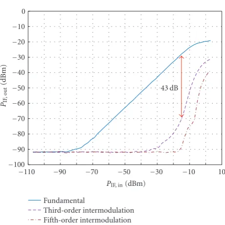
Figure7: Measured intermodulation for concatenated analog IF-to-RF up- and RF-to-IF down-converter modules.
from the noise floor (−100 dBm) to the maximum signal level expected for 1 m distance between transmit and receive antennas (−20 dBm).
2.4.5. RF measurements
Figure 7 shows the result of a two-tone experiment where the overall RF system was measured with the up- and down-converter modules concatenated via a 20 dB attenua-tor placed in between. Two synthesizers were used to create the 70 MHz±10 kHz input signal.
hp
C2
CH1S21 Log MAG 20 dB/ Ref 0 dB 1 : 2.533 dB 70.000 000 MHz BW: 14.423 322 MHz Cent: 72.461985 MHz Q: 5.0239 1
2
3 4
Center 70.000 000 MHz Span 40.000 000 MHz
Figure8: Measured frequency response for concatenated analog IF-to-RF up- and RF-to-IF down-converter modules.
Complex baseband data samples 2x 24 bits/sample
A
nalog
IF
sig
nal,
F
ig
.3
100 Msamples/s
14-bit ADC
Sin Cos Oscillator 0–50 MHz
Deci-mator 16–8192
FIFO
Figure9: Data flow in the receive PC, per channel.
2.5. The receive PC
The receive PC is remote-controlled by the transmit PC. It automatically down-converts the four incoming analog IF signals to digital baseband data samples at a maximum base-band sample rate of 6.25 MHz (seeFigure 9). This limits the maximum possible system bandwidth to about 6 MHz.
Down-conversion to baseband is carried out by an ICS 554 [9] PCI plug-in board and controlled by a server soft-ware which finally provides the received raw samples to the user of the testbed. Like in the up-converter boards, the down-conversion to baseband is carried out after the AD-conversion to avoid DC offsets and IQ imbalancing.
2.6. DSP/FPGA boards
In a rapid prototyping design flow, the first step for the algo-rithmic designer is to show the proof of concept by a Mat-lab implementation. In a second step, the algorithms can be mapped step-by-step on more realistic hardware plat-forms. To achieve this, the designer may extend his own PC (seeFigure 1) by FPGA and DSP boards (like the SMT 365 DSP/FPGA PCI plug-in boards [7] from Sundance) to inves-tigate critical parts of the design in a suitable real-time envi-ronment.
Complex baseband data samples 2x 24 bits/sample Main module:
RAM DSP FPGA
Optional extension modules:
RAM DSP FPGA
Figure10: Data flow in the DSP/FPGA modules.
These DSP/FPGA boards are equipped with a fixed-point DSP (600 MHz, 4800 MIPS peak performance, Texas Instru-ments TMS320C6416), a Xilinx FPGA (Virtex II XC2V1000-4-FF896), and 8 Mbytes of RAM as depicted inFigure 10.
By adding more DSP modules, a prototyping engineer can decide at a later stage how many DSPs are really required to meet real-time constraints since the 3L-Diamond oper-ation system also allows to map compiled procedures onto several DSPs.
High-speed data transfer (approximately 25 MBps) from/ to Matlab via the PC’s internal PCI bus is also possible; therefore, the initial, working, and tested receiver design implemented only in Matlab can be replaced part-by-part by signal processing algorithms executed directly on DSPs and/or FPGAs (Matlab MEX-files). This step-by-step replac-ing approach eases debuggreplac-ing and saves on code develop-ment time.
2.7. Matlab interface
An easy to use Matlab interface was developed to operate the overall testbed from one or more user PCs. Utilizing ordinary files to handshake and exchange data, this interface reduces code development and debugging time in a Matlab client ap-plication, in addition to making the testbed accessible from anywhere in the LAN (or even the internet by using a secure-FTP connection). Platform independence is guaranteed be-cause Matlab supports various operating systems. Optimized for the use as file servers, the transmit and receive PCs are able to store and provide user data without disrupting ongo-ing transmissions.
The following Matlab code presents a code example which transmits four identical 16-QAM signals on four chan-nels. Note that no hardware knowledge is needed to perform this transmission. In order to transmit data via the Matlab in-terface, a user sets up a channel and then the following steps need to be performed, all together not more than 15 lines of simple Matlab code.
(I)Generate complex baseband data sampleson a local PC in Matlab and it is optional to use DSP/FPGA boards. For example, four identical 16-QAM signals, RRC-filtered, four times oversampling, roll-offfactor=0.22 on each channel:
xTXData = [ randsrc(5000, 1, [-3 1 1 3]/3)...
+ j*randsrc(5000, 1, [-3 1 1 3]/3) ]; xFilter = rcosine (1, 4, ’fir/sqrt’, 0.22, 40); xTXData = rcosflt (xTXData, 1, 4, ’filter’, xFilter);
(II)Provide parameters. For example, transmit and re-ceive (3) the signal sixty times (60) with a delay of 40 ms (40) between subsequent blocks at a center frequency of 70.0 MHz (70.0) utilizing an interpolation of 64 (64) at the transmitter and of 32 (32) at the receiver. The other parameters can be used to utilize a lot of additional features as there are, for ex-ample, external clock synchronization, predesigned received signal filters implemented in the testbed hardware, and sev-eral possibilities of repeating measurements in order to re-ceive data for different channel realizations:
xTXOptions = [3,60,70.0,64,0,40,0,0,0,0,32,0,0]
(III)Save allthis to a .mat-file on a dedicated network path and create a second file to trigger the transmission:
xTXDir = ’\\Pollux\MIMO_TXData\’;
xFileName = ’Test 16 QAM’;
save([xTXDir xFileName ’.mat’],’xTXData’,’xTXOptions’); xFID=fopen([xTXDir xFileName ’.do’],’w’); fclose(xFID);
(IV)Wait for the received datato appear in a correspond-ing .mat-file file on a dedicated network path:
while size(dir([xTXDir xFileName ’.done’]),1)==0 pause(0.2); end;
(V)Process the receivedcomplex baseband datasamplesin Matlab (and it is optional to use DSP/FPGA boards to realize parts of the design in a real-time environment close to the final product). For example, print the magnitude of channel three of the 15th reception:
xRXDir = ’\\Castor\MIMO_RXData\’;
load([xRXDir xFileName ’_15.mat’]); stem(abs(double(xTXData(:,3))))
By using the Matlab interface, the user gains full flexibil-ity while it is still easy for him to perform and understand the first transmission of baseband data samples out of Mat-lab. Therefore, the user can focus on the data generation and reception algorithms (items 1 and 5) without “wasting” time devoted to hardware issues.
While the transmit PC and the receive PC load, process, and store data in real time and thus the whole data trans-mission is carried out in real time, the data transfer from and to the user PC (by the use of the Matlab interface) isnot real time. Especially if a form of real time feedback is not re-quired, this non-real-time transmission of data samples from and to the user PC does not change the investigation of, for example, an algorithm at all, but reduces cost on setting up the testbed in addition to making the overall testbed more convenient to use.
Up till now (April 2005), the testbed has been working flawlessly without any changes in hard- or firmware2for over 10 months.
2Only the RF frontend has been adapted for the needs of specific experi-ments.
Table1: Key parameters for typical testbed operation.
Channels Up to 4×4
Signal type (modulation) Any Samples per TX/RX blocka <131 072
TX DAC resolution 14 bits
TX intermediate frequency 70 MHz
Radio frequency 2.45 GHz
Transmit bandwidth <6.25 MHz RX intermediate frequency 70 MHz
RX ADC resolution 14 bits
Data transfer to hard disk <50 MBp/s
Time to fill hard disk (60 GB) approximately 20 min LAN transfer to client PC <9 MBp/s
aIf the sample data rate is smaller than 25 Msamples/s, a block can be up
to 20 000 000 samples long. (Otherwise the maximum block length is 131 072.)
2.8. Testbed summary
Real-time transmission experiments over an air interface are generally avoided due to the enormous costs, the hardware skills and software knowledge required, the uncontrollable and unpredictable environment of a real channel, and the unaffordable time until the first results may be achieved. Using the MIMO testbed developed, neither hardware pro-gramming skills nor a lot of time is needed to transmit and receive complex baseband data samples via air (or a pre-dictable channel built up of channel emulators).
The MIMO testbed developed (see Table 1) is able to transmit and receive complex baseband data samples on up to 4×4 antennas. Users can access this system from anywhere in the LAN by the use of simple Matlab commands (see code example). By implementing algorithms in Matlab and mi-grating their critical parts step-by-step in DSP/FPGA boards, researchers are enabled to detect design flaws in an upcoming product very early in the design process with minimum ef-fort. The experimental setup was kept very flexible (paramet-ric), allowing for various experiments supporting a multi-tude of wireless standards. While still maintaining flexibility, sharing the same RF hardware among several researchers and research teams significantly reduces the arising costs.
3. FIRST MEASUREMENTS
Since most MIMO systems are based on underlying SISO sys-tems, it appears useful to develop the baseband processing for a MISO implementation on the basis of a suitable suc-cessfully tested SISO link. Therefore, a 16-QAM transmitter and receiver was implemented in Matlab before continuing with further MISO transmissions.
100
10−1
10−2
10−3
10−4
10−5
BER
−3 0 3 6 9 12 15
SNR/bit (dB)
Theoretical Over IF
Over RF
Over RF and channel emulator 16-QAM
4-QAM
Figure11: Measured BER for a static SISO RF channel.
ZF, MMSE, and ML receiver. A detailed description of the applied synchronization will be given inSection 4when the succeeding MIMO implementation will be discussed.
3.1. End-to-end operation
First measurements were carried out by bypassing the chan-nel (seeFigure 1) and thus directly connecting the IF outputs of the transmit PC to the IF inputs of the receive PC, using a lowpass filter to suppress higher harmonics generated by the DA conversion. One Gbyte of data was transmitted error free using this setup.
3.2. Measurements via channel emulators
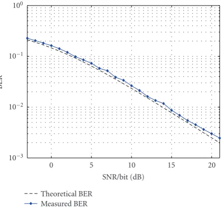
After successfully proving the basic transmitter and receiver operation, further SISO measurements were carried out uti-lizing channel emulators, and a noise generator. For a static channel (AWGN,Figure 11), as well as a slowly varying Ray-leigh fading channel (Figure 12), the measured bit error rate curves for 4-QAM modulation showed exact matching with well-known theoretical results within a margin of 0.2 dB.
3.3. Wireless SISO measurements
First measurements via an air interface were performed to get an impression on how the testbed works under real chan-nel conditions. The testbed configuration used in the above measurements was extended by a power amplifier and two of the earlier describedλ/4-monopole antennas. The receiver antenna (RX) was placed at a distance of about eight me-ters from the transmit antenna (TX) in a non-line-of-sight (NLOS) scenario (Figure 13). This kind of scenario was cho-sen because MIMO experiments will be accomplished using the same scenario.
100
10−1
10−2
10−3
BER
0 5 10 15 20
SNR/bit (dB) Theoretical BER
Measured BER
Figure12: Measured BER for a flat Rayleigh fading SISO RF chan-nel (4-QAM).
An RRC-filtered (roll-off= 0.22) 4-QAM signal with a block length of 8 000 symbols was transmitted in order to measure the BER of the received signal. The block length corresponds to a transmission time of approximately 5 mil-liseconds. Since the measurement was carried out inside a laboratory, and only slowly moving scatterers occurred, a constant channel can be assumed during the transmission of one data block. Additionally, since the symbol duration of 640 nanoseconds is about one order of magnitude larger then the delay spread of the indoor channel, we assume a chan-nel without any time dispersion. Because of the nonconstant measurement environment, the SNR of every received data block has to be estimated. Together with the calculated BER value, this gives the coordinates for one BER measurement point.
Figure 14 depicts the theoretical result for an AGWN channel compared to the measured data block results (cross-es). This comparison of BER values measured in a small-scale scattering environment with an AWGN channel is in-deed possible because of the separate SNR estimation of each received data block. Different SNR values were generated by varying the transmit power. By using the maximum available transmit power, an SNR value of about 25 dB was measured at the receiver.
4. MEASUREMENTS WITH MISO SPACE-TIME BLOCK CODES
Channel adaptive extended Alamouti code
2
.
9m
0.5 m 1.9 m
RX
C
o
rri
d
o
r
5
.
8m
1.9 m
3
.
5m
TX
7.7 m
Figure13: Measurement setup for the SISO transmission over the air: antennas are 1.4 m above the floor; room height is 3.5 m; the room contains a lot of tables, chairs, computers, and so forth.
100
10−1
10−2
10−3
10−4
10−5
BER
−3 −1 1 3 5 7 9 11 SNR/bit (dB)
Measured via air Theoretical (AWGN)
Figure14: Measured BER in smale-scale scattering setup.
were carried out to investigate this behavior for physical, im-perfect channels. Different channel realizations were created by channel emulators to obtain reproducible results.
4.1. Matlab transmitter
The transmitter, fully implemented in Matlab, generates complex data symbols from a 4-QAM constellation and per-forms extended Alamouti coding for four transmit antennas. Root raised cosine (RRC) filters produce the complex base-band samples of the transmit signals from the given symbols. These samples are transferred to the transmit PC via the Mat-lab interface as depicted inFigure 15.
. . . s4, s3, s2, s1
Code selection
Coding
Extended Alamouti space-time coding
Transmit filters
RRC filters Matlab interface
14-bit
comple
x
samples
Figure15: The CAEAC transmitter implemented in Matlab.
4.2. Channel setup
As described in Section 2.4, the channel is mainly com-posed of RF up- and down-converters and channel emulators which were used to generate flat Rayleigh fading. After the down-conversion process, the noise generator corrupts the IF signal with white Gaussian noise to allow BER over SNR measurements (seeFigure 3). The emulators can be substi-tuted by amplifiers and antennas to facilitate measurements over a real-time air interface once the correct functionality of the codes-under-test has been successfully proven.
4.3. Matlab receiver
The Matlab receiver, which obtains samples of the received IF signal via the Matlab interface, consists of the following blocks as illustrated inFigure 16.
Since the receiver PC does not know about the optimum sampling time instant, at least timing and frame synchro-nization have to be performed in Matlab. The frequency off -set estimation was initially also performed in Matlab, but to reduce calculation time, we decided to synchronize the frequency by using an external cable. This optional cable pro-vides a direct connection between the internal oscillator of the transmit PC (Figure 2) and the internal oscillator of the receive PC (Figure 9) to lock them in frequency.
The synchronization process is further simplified by the fact that the Matlab interface itself ensures (by triggering via the LAN) that the data is transmitted and received approx-imately at the same time. Although this does not by any means exactly synchronize transmitter and receiver, it does help to approximately know where the received data block starts. This knowledge allows for the later described maxi-mum search.Figure 17illustrates the synchronization algo-rithm which was implemented in Matlab to synchronize tim-ing and frame separately for every transmitted data block.
24-bit
comple
x
samples
Matlab interface
RRC filter Receive
filter
Synchro-nization See Fig. 17 Sampling time Frame (Frequency)
Feedback for code selection (0,1, or 2 bit)
Channel estimation
Channel coefficients
Detector
To BER measurement
To BER measurement
ZF, MMSE, ML
Figure16: CAEAC receiver implemented in Matlab.
1.5625 Msymbols/s
16 Correlator
Correlates received samples with the 4 training sequences First 100
training symbols of every transmit
antenna
6.25 Msamples/s Received samples
(4 times oversampled)
4 Interpolation filter Matlab spline interpolation
16 1.5625 Msymbols/s Received symbols
Figure17: Synchronization scheme in Matlab.
transmission frame. At last a down-sampling to symbol rate is performed and the receive symbols are delivered to the suc-ceeding stages of the Matlab receiver.
The synchronized data samples are then used for estimat-ing the channel coefficients in a least squares estimator. The channel estimator also selects the optimum extended Alam-outi space-time code for the transmission. This code selec-tion uses a feedback of at most two bits per frame to select one out of four codes. The actual implementation of the feed-back is described inSection 4.4.
By the use of the estimated channel coefficients, the detector reconstructs the transmitted symbols. A low-com-plexity solution of the maximum likelihood receiver [34] was implemented to measure the bit error rates for different numbers of feedback bits.
4.4. “Virtual” feedback
In the case of channel adaptive extendeded Alamouti codes, channel information is required to be fed back to the trans-mitter in order to select a code. The therefore needed real-time operation would typically require an implementation in FPGAs and/or DSPs. To avoid this time intensive task, the feedback necessary for the CAEAC was only implemented “virtually” which means transmitting all four possible codes in one large transmit block as depicted inFigure 18and se-lecting the optimum block in the receiver, rather than in the transmitter.
The transmitted block consists of four small data blocks, each coded with a different EAC, and a midamble as training
320 symbols code 3
320 symbols code 1
4×511 training symbols
320 symbols code 2
320 symbols code 4
Figure18: Structure of one transmit block.
Table2: Number of channel realizations per measurement point.
−3 dB≤SNR/bit<8 dB 15 000 channels 8 dB≤SNR/bit<12 dB 30 000 channels 12 dB≤SNR/bit≤17 dB 60 000 channels
sequence. The calculated feedback bits are not sent back to the transmitter; they are only used to select the optimum ex-tended Alamouti code block (for evaluating the BER) in the receiver. This procedure also allows for measuring the BER for 0 (just code 1 is used), 1 (either code 1 or code 2 is used), and 2 bit feedback (all four codes are used) with the same blocks of received data.
4.5. Measurement results with channel emulators
Smooth BER curves require a huge amount of data to be transmitted.Table 2indicates the number of different chan-nel realizations used for measuring the following BER curves. We used less channel representations for the lower-SNR regions since the BER is expected to be higher there. This amount of transmit data also required a large computational capacity. A cluster of ten personal computers running Matlab needed about one day to evaluate the received data.
Since the received data provided by the Matlab interface was already split up in files for the different SNR values, it suited perfectly the needs of a parallel processing cluster: self-written server-software-managed 14 client PCs, each evaluat-ing the BER for a specific block. By collectevaluat-ing all these results, the final BER plot (e.g.,Figure 19) was obtained. The effort needed to set up this processing cluster was still negligible compared to the effort which would have been necessary to code all these algorithms into DSP/FPGAs in order to gain more speed.
100
10−1
10−2
10−3
10−4
10−5
10−6
BER
−2 0 2 4 6 8 10 12 14 16 SNR/bit (dB)
ML-simulated 2-bit, 1-bit, 0-bit feedback Perfect 4x, 2x, 1x diversity
ML-measured 2-bit, 1-bit, 0-bit feedback
0 bit 0 bit 1 bit 2 bits 1 bit 2 bits 4x diversity
2x diversity No diversity
Figure 19: Measured BER curve for CAEAC coding (maximum
likelihood receiver).
4.6. Summary of measurements
The first SISO measurements performed on the MIMO testbed showed the perfect interaction of Matlab, the Matlab interface, the digital baseband hardware, the radio-frequency hardware, and the channel emulators. For static and fading channels, the measured bit error rate curves showed exact matching with well-known theoretical results.
The MISO measurements verified the simulated diversity improvement of the feedback used in channel adaptive ex-tended Alamouti codes.
5. CONCLUSION
Combining the advantages of Matlab and a DSP/FPGA en-vironment close to the final product, the MIMO testbed de-veloped allows for rapid verification of baseband algorithms and their critical parts with minimum effort. Proof of oper-ation has already been achieved by the successful implemen-tation of a channel adaptive extended Alamouti space-time code transmission showing excellent performance. Sharing very expensive equipment while still maintaining flexibility and ease of use directly out of Matlab (from any PC in the network), a testbed has been provided that allows for many new coding and modulation schemes to be conveniently in-vestigated in shortest time.
ACKNOWLEDGMENTS
The authors would like to thank Lukas Mayer, Ernst Aschbacher, Werner Keim, Stefan Geirhofer, Georg Maier, and Biljana Badic for their help and suggestions on improv-ing the testbed. This work has been funded by the Christian Doppler Laboratory for Design Methodology of Signal Pro-cessing Algorithms (http://www.nt.tuwien.ac.at/cdlab/).
REFERENCES
[1] D. Gesbert, M. Shafi, D.-S. Shiu, P. J. Smith, and A. Naguib, “From theory to practice: an overview of MIMO space-time coded wireless systems,” IEEE Journal on Selected Areas in Communications, vol. 21, no. 3, pp. 281–302, 2003.
[2] The MathWorks, MATLAB,http://www.mathworks.com/. [3] M. Rupp, A. Burg, and E. Beck, “Rapid prototyping for
wire-less designs: the five-ones approach,”Signal Processing, vol. 83, no. 7, pp. 1427–1444, 2003.
[4] M. Rupp, “On the influence of uncertainties in MIMO decod-ing algorithms,” inProceedings 36th Asilomar Conference on Signals, Systems and Computers, vol. 1, pp. 570–574, Monterey, Calif, USA, November 2002.
[5] A. Burg and M. Rupp, Chapter: Demonstrators and Testbeds, EURASIP Book on SMART Antennas, 2004,
http://www.nt.tuwien.ac.at/cdlab/ConferencePresenation/ DemonstratorsTestbeds.ps.
[6] Texas Instruments Incorporated, TMS320C6XXX DSPs,http: //dspvillage.ti.com/docs/allproducttree.jhtml?pageId=C6. [7] Sundance Multiprocessor Technology, SMT 365, http://
www.sundance.com/edge/files/productpage.asp?STRFilter= SMT365.
[8] Interactive Circuits Systems, ICS 564 Analog Output Boards,
http://www.ics-ltd.com/info/productInfo.cfm?ID=13&prod= 2.
[9] Interactive Circuits Systems, ICS 554 Analog Input Boards,
http://www.ics-ltd.com/info/productInfo.cfm?ID=10&prod= 1.
[10] Xilinx, System Generator, http://www.xilinx.com/products/ software/sysgen/features.htm.
[11] The Mathworks, Embedded Target for TI C6000, http:// www.mathworks.com/products/tic6000/.
[12] S. Geirhofer, C. Mehlfuhrer, and M. Rupp, “Design and real-time measurement of HSDPA equalizers,” in Proceedings of 6th IEEE Workshop on Signal Processing Advances in Wire-less Communications (SPAWC ’05), New York, NY, USA, June 2005.
[13] C. Mehlfuhrer, S. Geirhofer, S. Caban, and M. Rupp, “A flexi-ble MIMO testbed with remote access,” inProceedings of 13th European Signal Processing Conference (EUSIPCO ’05), An-talya, Turkey, September 2005.
[14] P. W. Wolniansky, G. J. Foschini, G. D. Golden, and R. A. Valenzuela, “V-Blast: an architecture for realizing very high data rates over the rich-scattering wireless channel,” in Pro-ceedings of International Symposium on Signals, Systems, and Electronics (ISSSE ’98), pp. 295–300, Pisa, Italy, September– October 1998.
[15] A. Adjoudani, E. C. Beck, A. P. Burg, et al., “Prototype ex-perience for MIMO BLAST over third-generation wireless system,”IEEE Journal on Selected Areas in Communications, vol. 21, no. 3, pp. 440–451, 2003.
[16] D. Garrett, G. Woodward, L. Davis, G. Knagge, and C. Nicol, “A 28.8 Mb/s 4×4 MIMO 3G high-speed downlink packet ac-cess receiver with normalized least mean square equalization,” inProceedings of IEEE International Solid-State Circuits Con-ference (ISSCC ’04), vol. 1, pp. 420–536, San Francisco, Calif, USA, February 2004.
[18] T. Kaiser, A. Wilzeck, M. Berentsen, and M. Rupp, “Proto-typing for MIMO systems - an overview,” inProceedings of 12th European Signal Processing Conference (EUSIPCO ’04), pp. 681–688, Vienna, Austria, September 2004.
[19] J. Rinas, R. Seeger, and K. D. Kammeyer, “A demonstrator for multi-antenna transmission - real channels and their impact on MIMO algorithms,” inProceedings of IEEE Radio and Wire-less Conference (RAWCON ’04) Workshop 2 on MIMO Imple-mentation Aspects, Atlanta, Ga, USA, September 2004. [20] T. Kaiser, A. Wilzeck, and R. Tempel, “A modular multi user
testbed,” inProceedings of IEEE Radio and Wireless Confer-ence (RAWCON ’04) Workshop 2 on MIMO Implementation Aspects, Atlanta, Ga, USA, September 2004.
[21] R. Morawski, T. Le-Ngoc, and O. Naeem, “Wireless and wire-line MIMO testbed,” inProceedings of IEEE Canadian Con-ference on Electrical and Computer Engineering (CCECE ’03), vol. 3, pp. 1913–1916, Montreal, Canada, May 2003.
[22] P. Murphy, F. Lou, A. Sabharwal, and J. P. Frantz, “An FPGA based rapid prototyping platform for MIMO systems,” in Pro-ceedings of 37th Asilomar Conference on Signals, Systems and Computers, vol. 1, pp. 900–904, Monterey, Calif, USA, Novem-ber 2003.
[23] J. W. Wallace, B. D. Jeffs, and M. A. Jensen, “A real-time mul-tiple antenna element testbed for MIMO algorithm develop-ment and assessdevelop-ment,” inProceedings of IEEE Antennas and Propagation Society Symposium (APS ’04), vol. 2, pp. 1716– 1719, Monterey, Calif, USA, June 2004.
[24] G. L. Stuber, J. R. Barry, S. W. McLaughlin, Y. Li, M. A. Ingram, and T. G. Pratt, “Broadband MIMO-OFDM wireless commu-nications,”Proceedings of the IEEE, vol. 92, no. 2, pp. 271–294, 2004.
[25] D. Borkowski and L. Br¨uhl, “Hardware implementation for real-time multi-user MIMO systems,” inProceedings of IEEE Radio and Wireless Conference (RAWCON ’04) Workshop 2 on MIMO Implementation Aspects, Atlanta, Ga, USA, September 2004.
[26] S. Ellingson, R. Mostafa, and J. H. Reed, “MIMO development efforts at virginia tech,” inProceedings of IEEE Radio and Wire-less Conference (RAWCON ’04) Workshop 2 on MIMO Imple-mentation Aspects, Atlanta, Ga, USA, September 2004. [27] S. H¨ane, D. Perels, D. S. Baum, et al., “Implementation aspects
of a real-time multi-terminal MIMO-OFDM testbed,” in Pro-ceedings of IEEE Radio and Wireless Conference (RAWCON ’04) Workshop 2 on MIMO Implementation Aspects, Atlanta, Ga, USA, September 2004.
[28] S. Caban, R. Langwieser, C. Mehlfuhrer, et al., “Design and verification of a flexible and scalable 4×4 MIMO testbed,” inProceedings of IEEE Radio and Wireless Confer-ence (RAWCON ’04) Workshop 2 on MIMO Implementation Aspects, Atlanta, Ga, USA, September 2004.
[29] E. Aschbacher, S. Caban, C. Mehlfuhrer, G. Maier, and M. Rupp, “Design of a flexible and scalable 4×4 MIMO testbed,” inProceedings of 11th IEEE Digital Signal Processing Workshop (DSP ’04),pp. 178–181, Taos Ski Valley, NM, USA, August 2004.
[30] Spirent, TAS4500 FLEX RF Channel Emulator, http://www. atsweb.it/Images/Documenti/TAS DS 4500.pdf.
[31] 802.11b, Part 11: Wireless LAN Medium Access Control (MAC) And Physical Layer (PHY) Specifications: Higher-speed
Physical Layer Extension In The 2.4 GHz Band, pp. i–90. IEEE Standard 802.11b-1999, 2000, http://ieeexplore.ieee. org/iel5/6642/17714/00817038.pdf.
[32] Noisecom, UFX-EBNO-IF1 Precision Noise Generator,
http://www.noisecom.com/content/Products/Components/
UFX EbNo/UFX EbNo.pdf.
[33] B. Badic, M. Rupp, and H. Weinrichter, “Quasi-orthogonal space time block codes for data transmission over four and eight transmit antennas with very low feedback rate,” in5th International ITG Conference on Source and Channel Coding (SCC), pp. 157–164, Erlangen-N¨urnberg, 2004.
[34] C. F. Mecklenbr¨auker and M. Rupp, “Generalized Alam-outi codes for trading quality of service against data rate in MIMO UMTS,”EURASIP Journal on Applied Signal Process-ing, vol. 2004, no. 5, pp. 662–675, 2004.
Sebastian Cabanwas born in Vienna, Aus-tria, on March 13, 1980. Studying electri-cal engineering at the Vienna University of Technology, he received several scholarships as the best student of the college. During his diploma thesis he worked at the university’s Institute of Communications and Radio-Frequency Engineering where he codevel-oped the MIMO testbed presented in this paper. Currently he is continuing his study
of communication engineering at the University of Illinois at Urbana-Champaign, USA. His research interests focus on rapid prototyping of MIMO systems.
Christian Mehlf¨uhrerwas born in Vienna, Austria, in 1979. In 2004 he received his Dipl.-Ing. degree in electrical engineering from the Vienna University of Technology. Besides his diploma studies he worked part-time at Siemens AG where he performed integration tests of GSM carrier units. Af-ter finishing his diploma thesis on imple-mentation and real-time testing of space-time block codes at the Institute of
Com-munications and Radio-Frequency Engineering, Vienna Univer-sity of Technology, he started working on his doctoral thesis at the same institute. His research interests include rapid prototyp-ing, experimental investigation of MIMO systems, the upcoming UMTS MIMO HSDPA mode, and the MIMO extension for WLAN (802.11n).
Robert Langwieserreceived his Dipl.-Ing. degree in electrical engineering from the Vienna University of Technology, Austria, where he is currently working towards his Ph.D. degree at the Institute of Communi-cations and Radio-Frequency Engineering. He is employed as a Project Assistant and is Member of the Christian Doppler Labora-tory for Design Methodology of Signal Pro-cessing Algorithms. The focus of his recent
Arpad L. Scholtzwas born on January 19, 1947 in Kecskemet, Hungary. In 1956 he moved to Austria and received the Austrian citizenship in 1960. He studied telecommu-nications at the Vienna University of Tech-nology, where he earned his Masters de-gree in 1972 and the Ph.D. dede-gree in 1976, both with distinction. From 1972 to 1982, Dr. Scholtz worked as an Assistant Profes-sor for radio-frequency engineering at the
Institute of Communications and Radio-Frequency Engineering. Since 1982, Dr. Scholtz additionally has been serving at the same Institute as a Lecturer, and in 1992 he was given the title of Asso-ciate Professor. Arpad L. Scholtz is Author or Coauthor of more than a hundred scientific publications. He teaches radio-frequency engineering with emphasis on electronic circuit design, antennas, and point-to-point communications. His hobbies are amateur ra-dio and digital photography.
Markus Ruppreceived his Dipl.-Ing. degree in 1988 from the University of Saarbr¨ucken, Germany, and his Dr.-Ing. degree in 1993 from the Technische Universitaet Darm-stadt, Germany, where he worked with Eberhardt Haensler on designing new al-gorithms for acoustical and electrical echo compensation. From November 1993 until July 1995, he had a postdoctoral position at the University of Santa Barbara, California,