Type of the Paper (Article)
1
Open Source Completely 3-D Printable Centrifuge
2
Salil S. Sule1, Aliaksei L. Petsiuk2 and Joshua M. Pearce 2,3,4*
3
1 Department of Mechanical Engineering–Engineering Mechanics, Michigan Technological University,
4
Houghton, MI, 49931; [email protected]
5
2 Department of Electrical & Computer Engineering, Michigan Technological University, Houghton, MI,
6
49931; [email protected]
7
3 Department of Material Science & Engineering, Michigan Technological University, Houghton, MI, 49931;
8
9
3 Department of Electronics and Nanoengineering, School of Electrical Engineering, Aalto University, Espoo,
10
Finland, FI-00076; [email protected]
11
* Correspondence: [email protected]; Tel.: +01-906-487-1466
12
13
Abstract: Centrifuges are commonly required devices in medical diagnostics facilities as well as
14
scientific laboratories. Although there are commercial and open source centrifuges, costs of the
15
former and required electricity to operate the latter, limit accessibility in resource-constrained
16
settings. There is a need for low-cost, human-powered, verified and reliable lab-scale centrifuge. This
17
study provides the designs for a low-cost 100% 3-D printed centrifuge, which can be fabricated on
18
any low-cost RepRap-class fused filament fabrication (FFF) or fused particle fabrication (FPF)-based
19
3-D printer. In addition, validation procedures are provided using a web camera and free and open
20
source software. This paper provides the complete open source plans including instructions for
21
fabrication and operation for a hand-powered centrifuge. This study successfully tested and
22
validated the instrument, which can be operated anywhere in the world with no electricity inputs
23
obtaining a radial velocity of over 1750rpm and over 50N of relative centrifugal force. Using
24
commercial filament the instrument costs about US$25, which is less than half of all commercially
25
available systems; however, the costs can be dropped further using recycled plastics on open source
26
systems for over 99% savings. The results are discussed in the contexts of resource-constrained
27
medical and scientific facilities.
28
Keywords: 3-D printing; additive manufacturing; biomedical equipment; biomedical engineering;
29
centrifuge; design; distributed manufacturing; laboratory equipment; open hardware; open source;
30
open source hardware; medical equipment; medical instrumentation; scientific instrumentation
31
32
1. Introduction
33
Adopting an open-source model of technological development enables equipment designers to
34
quickly build upon one another’s works [1-3]. This democratization of design assists many
35
individuals to effectively work together by making a range of contributions over time using open
36
source tools [4-6]. Some of the most effective tools for encouraging widespread open hardware
37
designs are themselves means of digital distributed manufacturing [7,8]. For example, the open
38
source nature of the self-replicating rapid prototyper (RepRap) 3-D printer [9-11] radically increased
39
the accessibility to additive manufacturing (AM) while eviscerating the costs of rapid prototyping
40
and product fabrication [12-16]. RepRaps and derivative commercial variants have obtained
41
mechanical 3-D printed part strengths [17] and qualities of interest to the scientific community [18].
42
Many open source digitally fabricated devices are now widely used by the scientific community
[19-43
21]. For example, 3-D printed parts are used in chemical mixing [22-25], optical and mechanical
44
testing [26-28], water quality testing [29-32], and syringe pumping [33-36] (which can be in turn used
45
for more complicated systems like fabricating microfluidics and metafluidics [37-39] or slot die
46
deposition [40]). In addition to offering scientists the ability to customize their equipment and fully
47
control its function, the open source 3-D printable tools are much less expensive than equivalent or
48
inferior commercial systems [19,41, 42]. In general, these economic savings are greater for the higher
49
percentage of the components able to be 3-D printed [43]. A high return on investment (ROI) is
50
realized for distributed manufacturing with commercial polymer 3-D printing filament based on
51
downloaded substitution values [44,45]. In order to continue to ‘stand on the shoulders of giants’ in
52
open hardware [46] this paper describes the design of an open source completely 3-D printable
53
centrifuge.
54
A centrifuge is a machine that holds rapidly rotating containers while applying centrifugal force
55
to the fluids inside the containers to separate them based on different densities. Centrifuges are
56
commonly required devices in medical diagnostics facilities because they are used for determining
57
the concentration of pathogens and parasites in biological fluids, DNA preparation, and extraction of
58
plasma from whole blood needed for immunoassays or haematocrit analysis. There are many
59
commercial laboratory centrifuges and a number of open source variants including the open
60
analytical ultracentrifugation (AUC) [47], the laser cut OpenFuge [48], Polyfuge [49], several
61
variations of mini centrifuges [50-52], and one that uses a Dremel and 3-D printed chuck [53]. These
62
open hardware tools do provide for those without access to more expensive proprietary tools [54],
63
however, they all depend on access to electricity. Unfortunately, an estimated 1.1 billion people (e.g.
64
14% of the global population) do not have access to electricity [55]. In addition, even many of those
65
that do have access to electricity, have unreliable power. For example, in Nigeria power outages over
66
extended times have forced a shift to expensive and polluting captive power generation in the
67
majority of businesses [56]. To overcome this challenge of reliable electric power, several open source
68
hand powered centrifuges have been developed including the paperfuge [57], a salad spinner
69
centrifuge [58], and an eggbeater centrifuge [59]. All of which are functional, but lack either large
70
volume capabilities [57] or reliability. To overcome this, several companies have commercialized
71
relatively robust hand-crank centrifuges, which cost US$60-100 [60,61]. These costs can still be
72
prohibitive and as centrifugation is the first key-step for most diagnostic assays [62], there is a need
73
low-cost, portable, human-powered centrifuge that can be used by scientists and medical personnel
74
especially for diagnostics in resource-limited environments [62-64].
75
This study provides the designs for a low-cost 100% 3-D printed centrifuge apparatus, which
76
can be fabricated on any low-cost RepRap-class fused filament fabrication (FFF) or fused particle
77
fabrication (FPF)-based 3-D printer. In addition, a validation procedure for quantifying the rotational
78
speed is provided, which makes use of a smart phone or web camera. The design is fabricated and
79
tested and the results are discussed in the contexts of resource constrained medical and scientific
80
facilities.
81
82
2. Materials and Methods
83
2.1 Design
84
The design goal for this apparatus was to provide 1200 rotations per minute (rpm) with a handle
85
rotational speed of the operator (N1) of 120 rpm (i.e. 2 rotations in 1 second). This centrifuge
86
apparatus uses one set of spur gears and one set of bevel gears to achieve the desired gear ratio.
87
2.1.1. Gear designing and final drive calculations
88
Considering the rotational speed of the handle by the operator, N1 is 120 rpm the rotational speed
89
for the 2nd spur gear, N2 is:
90
N2= N1T1 / T2 (1)
91
Teeth on 1st Spur gear : T1 = 60
93
Teeth on 2nd Spur gear : T2 = 15
94
Teeth on 1st Bevel gear : T3 = 50
95
Teeth on 2nd Bevel gear : T4 = 20
96
So N2 is 480 rpm and as the 2nd spur gear and 1st bevel gear are coupled together,
97
N2 = N3 (2)
98
Thus,
99
N4= N3T3 / T4 = N2T3 / T4 (3)
100
So, N4 is 1200 rpm. Similarly, for N1 of 150 rpm (i.e. 2.5 rotations of the handle per second) the final
101
rotor speed is 1500 rpm.
102
Thus, for this apparatus the number of test-tube rotations (rt) is given by
103
rt = Crh (4)
104
Where the hand rotations per minute (rh) can be measured and C is a constant of 10. With these
105
parameters it is also possible to calculate the relative centrifugal force (RCF), which is the amount of
106
acceleration that is exerted on the sample in the apparatus. The RCF is dependent on the speed of the
107
rotor and the distance of the matter in the test tubes from the center of the rotation. When the unit of
108
rotation (N4) is in rpm, RCF is given by:
109
RCF = 1.118 x 2 x 10-6 x R [mm] x N42 [rpm] (5)
110
Where R is the radius of rotor to the center of test tubes used added to the test tube length (mm) and
111
N4 is given by equation 3. In the example shown here with the radius of the rotor (50mm) test tubes
112
used and length of test tubes (100mm) providing a total of 150 mm and N4 of 1500 rpm the RCF is
113
755.
114
115
2.1.2 Operation of design
116
1. Rotating the handle will rotate the bigger spur gear, which will start the motion. The two spur
117
gears in contact have equal modules. Module is the ratio of the reference diameter of the gear to the
118
number of teeth on the gear. The bigger spur gear has 60 teeth and a module of 2. Although a larger
119
spur gear would have yielded a higher gear ratio, it would also have increased the size of the casing
120
and in turn the size of whole apparatus. A spur gear with 60 teeth and a module of 1.5 module was
121
chosen considering the need of the final required rotations of the rotor (N4). Meshed to the bigger
122
spur gear is a smaller spur gear with an equal module. To mesh and rotate a set of any gears, it is
123
necessary that both the gears should have the same profile and an equivalent module. This smaller
124
spur gear is coupled with a larger bevel gear to eliminate the overhang and also another component
125
required to hold the two together. The bigger bevel gear has 50 teeth and a module of 2. The bevel
126
gear is used to transmit the motion in perpendicular direction. A smaller bevel gear is then meshed
127
with the large one to increase the rotations per minute of the test tubes.
128
2. High rotational speeds of 1200-2000 rpm are required to carry out typical medical tests. Thus,
129
this gear train is designed in such a way that, with every two rotations per second, the rotor will
130
rotate at 1200 rpm. With every two and half rotations per second of the handle, the rotor will rotate
131
at 1500 rpm and with three rotations per second, it can do 1800 rpm. The commercial equivalent
132
products are capable of rotating at 1800 rpm, which is equal to the rotational capability of this 3-D
133
printed centrifuge apparatus. The speeds can be easily increased if the number of teeth on either of
134
the bevel or spur or both bigger gears are increased and the source code in FreeCAD is made available
135
3. The dimensions of the handle is designed in such a way that, it will not interfere with rotation
137
of the test tubes. The grip is designed keeping the ergonomics of the human hand and its motion
138
while rotating the handle in mind. Enough grip is provided on the grip bar that freely rotates around
139
the centerpiece of handle. The horizontal motion of grip is constrained by implementing a ball-socket
140
joint at the end of the handle.
141
4. Test tubes are placed in the test rings, which are specifically designed for standard test tubes.
142
However, there is a wide variety of test tubes that are available on the market. All the part files in
143
FreeCAD are made available and open source so that others can adapt the tube holders to meet other
144
sizes of test tubes. The test rings that hold the test tubes are locked in the rotor by using rotor snaps.
145
These snaps can easily withstand the high centrifugal forces acting on them as they are tightly fit in
146
the rotor itself. The rotor diameter is 120 mm, which is enough to generate high centrifugal force
147
following equation 4.
148
2.1.3 Bill of Materials
149
The bill of materials (BOM) is made up of all 3-D printed components, which are summarized in
150
Table 1.
151
Table 1. Bill of materials for the 3-D printed open source centrifuge.
152
Component Quantity Description Image of Component
Part A 1 Front plate
Part B 1 Back plate
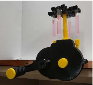
Part C 1 Bigger spur gear with locking pin
Part D 1
Smaller spur gear with large bevel
Part E 1 Smaller bevel gear
Part F 1
Clamping ring for smaller bevel gear
(Part E)
Part G 1 Rotor for test tubes
Part H 1 Clamping for Part D
Part I 4 Rings for test tube
Part K 2 Bolts for clamping body
Part L 2 Base clips for the bolts
Part M 1
Smaller bevel gear holder
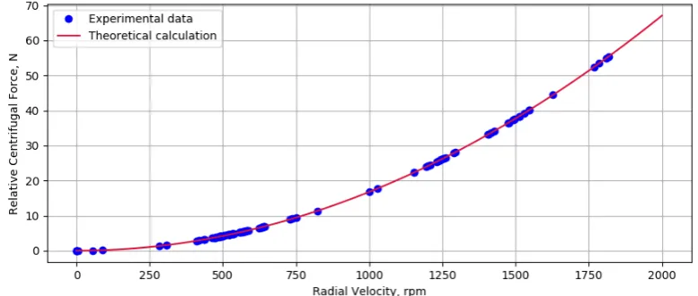
Part N 1 Handle
Part O 1 Grip for handle
Part P 1 Locking clip for handle
2.2 Fabrication
153
The components shown in Table 1 and available on the Open Science Framework [66] in both
154
from a creative commons-licensed C-clamp design [68]. All of the parts were 3-D printed with
glycol-156
modified polyethylene terephthalate (PETG) IC3D filament of diameter 2.85mm on a Lulzbot TAZ 6
157
(Aleph Objects, Loveland CO). The objects were sliced with Cura Lulzbot edition v.3.6.3 [69] using
158
the standard settings summarized in Table 2.
159
160
Table 2. Slicer settings for each 3-D printed part
161
Part Name Pre-defined settings (layer height)
Infill (%)
A High speed (0.38 mm) 40
B High speed (0.38 mm) 40
C Standard (0.28mm) 65
D Standard (0.28mm) 60
E Standard (0.28mm) 60
F High speed (0.38 mm) 90
G High speed (0.38 mm) 40
H High speed (0.38 mm) 40
I Standard (0.28mm) 50
J Standard (0.28mm) 60
K Standard (0.28mm) 50
L High speed (0.38 mm) 50
M High speed (0.38 mm) 65
N High speed (0.38 mm) 75
O High speed (0.38 mm) 45
P High speed (0.38 mm) 40
2.3 Assembly
162
All the parts of the centrifuge apparatus are shown in Table 1 from Part A through part O. The
163
assembly of the open source centrifuge can be accomplished after the printed parts are prepared as
164
follows. Part C is the big spur gear whose end part (square shaped) needs to be scraped with a knife
165
or any sharp object before starting the assembly. Make sure to scrape a little material from the four
166
edges on the square shaped end of Part C to ensure a tight fit between Part C and the handle (Part
167
N). This is an important step as a tight fit will make rotating the handle easy and effective. All the
168
holes on Part A and Part B need to be scraped a little to ensure smooth rotations of the respective
169
gears. This problem is created due to non-uniform printing by the FFF printer. The four sockets on
170
Part A are to be scraped as well for perfect fitting of the ball joints of Part B. Carefully remove small
171
amount of material from all four sockets if the ball joints are not fitting inside the sockets. This
172
operation may require some extra force. Part A and Part B are the two casings, which cover the gear
173
train of the apparatus. Start assembling with Part B as the gears are meshed inside this part.
174
176
Figure 1. Assembling Parts B and C
177
Part B has two holes of equal diameters where the gears are placed in order to carry out correct
178
meshing. The right hand side of the part B has smaller diameter casing than the left hand side. Place
179
Part C, which is the bigger spur gear through the hole on the right hand side (smaller casing side as
180
seen in Figure 1). Lock the spur gear from the backside with the small connecting pin, which is
181
included in the Part C. This will help to constrain the horizontal movement of the spur gear and
182
will keep the shaft in place while rotating.
183
184
Figure 2. a) Inserting Part E into Parts B and b) inserting Part D.
185
186
Now insert Part E through the bigger circle situated on the top of Part B and hold it at the top
187
(Figure 2a). Then insert Part D, which is the part with coupled gears, through the hole on the left side
188
of Part B (Figure 2b).
189
190
Figure 3. a) Attaching Part H and b) Part E.
191
Attach part H from the backside of the Part B in the Part E’s hole, which will hold the couple
192
gears in one place and stop it from swiveling abruptly while rotating (Figure 3a). Then, place Part F
193
195
Figure 4. a) Inserting part M and b) assembling Parts K and c) L.
196
Part A is the other half of the casing, which is used to cover the gear train and clamping. Part A
197
and Part B are clamped to each other using four ball-socket joints. Insert Part M through the Part E’s
198
square end and fix it to the casing through the three given holes (Figure 4a). This will help the small
199
bevel gear to align perfectly in the vertical direction during rotations. Part K and Part L are used to
200
clamp the whole centrifuge body to any even surface. Join both parts after the Part K is passed
201
through the Part A’s internal threading. Join Part K and Part L using the ball-socket joint (Figure 4b).
202
203
204
Figure 5. a) Attaching handle N, and b) grip and c) lock.
205
206
Part N, Part O and Part P are the components of the handle. Lock the Part N in the square end
207
of Part C. Make sure to scrape some material with the help of knife or any sharp object from the
208
Part C’s square end to tight fit Part C with Part N. If sufficient material is not scraped then Part C
209
will not fit with Part N, and if it is scraped more than the handle will fit loosely which will create
210
snapping problem while rotating the handle. Part O is the grip, which is used to rotate the handle.
211
Fix Part O and Part P with the ball-socket joint to fix the Grip.
212
213
Figure 6. Assembling a) Part G, b) Part I and c) Part J.
214
215
Part G, Part I and Part J are the parts of the rotor assembly. Part G is the rotor that will hold the
216
rings (Part I) and the snaps (Part J). Place the rings in the rotor and clamp the rings by placing the
217
snaps into the rotor. This will prevent the rings from falling during the motion due to high centrifugal
218
force.
219
After completing the assembly, clamp the centrifuge apparatus on one side of a table (preferably
221
a rectangular table and not a circular one). Place the test tubes in the test tube rings carefully. It is
222
extremely important to balance the weight of the test tubes equally. Leaving out test tubes or heavily
223
loading one will cause vibrations and will make the whole apparatus unstable while in operation. If
224
only 3 of the test tubes are used for sample testing, make sure to fill the fourth test tube with water
225
or a liquid that is of similar density that of the sample. This will ensure equal distribution of weight.
226
Crank the handle, which is equipped with a grip.
227
2.5 Validation
228
As the working part of the centrifuge rotates at a speed of up to 2,000 rpm, it may be difficult to
229
track its motion since the majority of regular web cameras are operating at a frequency of 25-30 Hz.
230
Thus, as the whole system represents a mechanical transmission with the fixed gear ratio, an indirect
231
method was chosen to calculate the angular velocity of the tubes based on the speed of rotation of
232
the centrifuge handle (Figure 7).
233
A Python-based software was developed to automatically measure the rotational speed of the
234
centrifuge. The OpenCV library [70] for segmentation and tracking a visual marker located on the
235
centrifuge handle, and PyQt library [71] were used for creating an open source guided graphical user
236
interface (GUI) application (Figure 8) [72].
237
238
Figure 7. Image-based markers segmentation a) Cropped frame of the centrifuge with the visual
239
markers, b) Masked image c) Calculated handle orientation.
240
241
The developed application allows users to crop an arbitrary region of interest of the captured
242
camera frame and set RGB thresholds for tracking the visual markers of any distinctive colors. It
243
counts the number of centrifuge handle revolutions and calculates angular velocity of the tubes. With
244
the given information about the tube length, the program also computes its relative centrifugal force.
245
In the case of normal manual rotation, the central marker will be periodically covered by the
246
hand/arm of the user, so it is possible to set the x and y coordinates of the origin point in the program
247
code.
248
250
Figure 8. A screenshot of the open source biometical centrifuge interface for camera-based RPM
251
and RCF calculations.
252
The main computer vision algorithm is provided below. The RPM and RCF calculations are
253
based on tracking the coordinates of the traveler marker located on the centrifuge handle. By
254
applying the specified color thresholds and morphological operations of “opening” and “closing” to
255
a cropped camera frame the user can mask the marker as a single separated color region. To find the
256
coordinates of its centroid the method of moments is employed, which will allow the centrifuge
257
handle orientation relative to the center of rotation to be calculated. To do this 𝑅𝑅𝑅𝑅𝑅𝑅𝑇𝑇, the rotational
258
velocity of the tubes in rpm is given by:
259
260
𝑅𝑅𝑅𝑅𝑅𝑅𝑇𝑇 =𝐺𝐺 ⋅60Δ𝑡𝑡 (6)
261
262
where, G, is the gear ratio and Δ𝑡𝑡 is the time interval for a single revolution in seconds. The RCF
263
in Newtons is given by:
264
265
𝑅𝑅𝑅𝑅𝑅𝑅= 1.118⋅10−6⋅ 𝐷𝐷 ⋅ 𝑅𝑅𝑅𝑅𝑅𝑅 𝑇𝑇
2 (7)
266
Where D is the length of the test tube with the radius of the centrifuge rotor in mm. A series of
267
eight experiments for various rotational speeds for an RCF(RPM) plot are performed to compare the
268
theory to experiment. Such a validation experiment is recommended for those building their own
269
centrifuge before deployment. Depending on the critical nature of the application of the open source
270
centrifuge, users may wish to record and run the validation for every experiment or simply keep
271
track of the approximate number of rotations and rotations/minute of the handle to obtain an
272
approximate RPM/RCF.
273
274
As can be seen in Figure 8, the user can set the RGB thresholds and crop the region of interest in the
275
video. Users can also set the tube length and gear ratio to calculate the RPM and RCF. The RCF and
276
relative velocity are plotted in real time. The pseudo code is given as follows:
277
278
Computing angular velocity and relative centrifugal force Input: an image frame from a camera or a video sequence Output: RPM and RCF values for the test tubes
crop the region of interest of the image frame apply linear filtering to blur the cropped region mask color marker using RGB thresholds
apply operations of opening and closing to remove noise after RGB masking find the contours of the masked area
if the traveler marker is detected do:
find the centroid location of the color marker applying the method of moments calculate the radius of rotation and the angle of the centrifuge arm
if the angle is in a specified zero range do: increase number of revolutions by one
update timer and compute the time period for one revolution calculate the tubes RPM
calculate the tubes RCF end if
end if end while
2.6 Economic Analysis
279
In order to determine the costs for the apparatus the entire device was massed on a digital scale
280
+/-0.01 kg. The total cost (Tc) of the apparatus can be determined by:
281
Tc = mCe + mCp (8)
282
Where m is the mass of all the 3-D printed parts (e.g. the whole apparatus), Ce is the cost of the
283
electricity per kg to print and Cp is the cost of plastic per kg. The electricity to operate the Lulzbot Taz
284
6 is about 9.11 kWh per kg as measured by a multimeter +/- 0.01 kWh. The average cost of commercial
285
electricity in the U.S. is $0.1029/kWh [73]. This value was used assuming that the device was
286
fabricated at a university or government laboratory, which would be considered a mid-range value
287
between those fabricating it using residential electricity rates (higher) and distributed solar
288
photovoltaic electricity (lower). The cost of IC3D filament from Lulzbot was US$45/kg [74].
289
3. Results
290
All of the parts of the open source centrifuge can be printed on the standard RepRap-class
FFF-291
based 3-D printer. Here all the parts were printed on a Lulzbot Taz 6 using standard print settings in
292
PETG. Part A and Part B are the longest prints, which take more than 8 hours to complete each. All
293
the gears are printed with more than 60 % fill, thus they have the printing times of more than 3 hours.
294
The total printing time for all the parts is about 35 hours. The printing time can be reduced if the
295
‘High speed’ (0.28mm z height) pre-defined setting is used with reduction in the infill percentage up
296
to certain level. In addition, a nozzle with a larger orifice would also speed printing.
297
The open source centrifuge takes about 30 minutes to assemble after printing all the parts if all
298
the instructions in Section 2.3 are carefully followed. The open source centrifuge is shown fully
299
assembled in the pre-spin state clamped to a desk in Figure 9. The complete system with filled test
300
tubes is shown during rotation in Figure 10a and a screen capture of a centrifuge cam used for the
301
GUI is shown in Figure 10b. Note the blue tape on the handle end to enable easy computer vision
302
analysis. The same functionality can be obtained using a different colored 3-D print for part P,
303
coloring it with a marker, or using a sticker. To see the device in operation see the Video S1:
304
306
Figure 9. Fully assembled open source centrifuge in the pre-spin state.
307
308
309
Figure 10. a) complete system with filled test tubes during rotation and b) a screen capture of a
310
centrifuge cam used for the GUI. Tracking of the handle marker, time, angle, number of revolutions,
311
RPM and RCF are all shown in real time.
312
During validation experiments with filled test tubes, the RCF(RPM) function was obtained for a
313
wide range of rotational velocities and compared to theory (Figure 9). As can be seen in Figure 9 the
314
316
Figure 11. Relative centrifugal force as a function of the rotational velocity of the centrifuge test
317
tubes.
318
4. Discussion
319
This study successfully described, tested and validated a completely open source centrifuge,
320
which can be fabricated using only open source tools, validated with a laptop computer with webcam
321
using only free and open source software, and operated anywhere in the world with no electricity
322
inputs. In addition, this device can be fabricated for far less than commercial proprietary tools. The
323
total mass of the apparatus is 0.550 kg, which results in about US$0.50 in electricity costs and $24.75
324
in commercial costs of filament for a total cost of US$25.26. This compares to commercial systems,
325
which cost US$60-100 [60,61] and do not have a means of easy field validation without the use of the
326
open source GUI disclosed here. Thus, a considerable saving of 57-75% decrease in cost can be
327
achieved with this device. However, as this device is primarily developed for applications in
328
resource-constrained settings, further cost reductions are needed.
329
The economics of using commercial 3-D printing filament are somewhat attractive, however,
330
they can be improved by using filament fabricated with a recyclebot [75-77] from recycled waste
331
polymers. Former 3-D printed polymers can be recycled with acceptable mechanical strengths for
332
about five cycles [78,79]. Thermopolymers, which already demonstrated with recyclebot processing,
333
include: polylactic acid (PLA) [77-81], PET and PETG [82-84], high-density polyethylene (HDPE)
334
[76,84-89], acrylonitrile butadiene styrene (ABS) [84,88-92], polystyrene (PS) [84], polypropylene (PP)
335
[84,], elastomers [93] as well as polypropylene blends [94] and composites like waste wood
336
biopolymers [95] and carbon fiber reinforced plastics [96]). Modern recyclebots can make filament
337
from waste plastic for electricity costs between 2.4 [92] and 3.6 [77] cents/kg. As the design here
338
massed as 0.550 kg, it would cost between 1.3 and 2 cents in recycled filament and about 91 cents to
339
print, which results in a total cost of about US$0.92-$0.93. This provides savings of 98-99% compared
340
to commercial offerings. However, there are two ways these costs can be even further reduced. The
341
first involves using a previously acquired solar photovoltaic powered recyclebot [80,89,91] and
342
solar powered 3-D printer [89,91,97-99]. The electricity costs are then avoided dropping the marginal
343
costs of materials and energy near zero, although the capital cost would need to be amortized by
344
printing many valuable products or be given as a donation. In addition, direct fused particle
345
fabrication (FPF) or fused granular fabrication (FGF) can be used to recycle a wide range of materials
346
including PET, PP, ABS, and PLA [100]. Directly printing shredded waste plastic takes the cost of the
347
materials and processing of the open source centrifuge down under US$0.50. The commercial open
348
source FPF/FGF systems have high capital costs although they can fabricate generally large valuable
349
products that provide users with a high return on investment if they are used frequently [101].
350
This study indicates several areas of future work. First, more research is needed to make
small-351
scale FPF/FGF 3-D printers to fabricate waste plastic into open source centrifuges for resource
352
also look at the potential for a 3-D printable waste plastic shredder – again ideally solar or manual
354
powered that could be used to complete the entire tool chain from waste to finished scientific
355
instrument. It should be noted in the cost calculations above, the labor costs were not included. Future
356
work can address the labor costs in a range of contexts, however, past analysis of open hardware for
357
science by Trivedi et al. [102] have shown that zero labor costs are relevant for several scientific
358
instrument situations where: i) there is no opportunity cost to using existing salaried employee (e.g.,
359
lab managers, research assistants, teaching assistants or other position that is paid a fixed cost, and
360
for which there is no opportunity cost for them working on the fabrication of the device); ii)
361
fabrication of the instruments is used as a learning aid [103,104]; or iii) the labor is provided by unpaid
362
interns or volunteers (e.g., undergraduate students volunteering for research experience). In general,
363
in resource-constrained settings as well as most academic institutions these conditions can be met.
364
For those settings where this is not the case, the tasks to order and deploy a commercial product
365
should be compared to the relatively low-time investment of printing (only set up and take off
366
necessary as the 3-D printers can be left unattended) and assembling the open source centrifuge.
367
5. Conclusions
368
This paper provides the complete open source plans including the BOM, instructions for
369
fabrication and operation, and open source software for a hand-powered centrifuge. This study
370
successfully described, tested and validated this completely open source centrifuge, which can be
371
fabricated using only open source tools (e.g. RepRap-class 3-D printer). Further, the validation itself
372
uses only open source and readily available tools of a computer with webcam. The instrument can
373
be operated anywhere in the world with no electricity inputs obtaining a radial velocity of over
374
1750rpm and over 50N of relative centrifugal force. Using commercial filament the instrument costs
375
about US$25, which is less than half of all commercially available systems; however, the costs can be
376
dropped further using recycled plastics on open source systems for over 99% savings.
377
Supplementary Materials: Video S1: MOST_CENTRIFUGE_VIDEO.avi.
378
Author Contributions: Conceptualization, Joshua M. Pearce; Data curation, Aliaksei L. Petsiuk; Formal analysis,
379
Salil S. Sule, Aliaksei L. Petsiuk and Joshua M. Pearce; Funding acquisition, Joshua M. Pearce; Investigation, Salil
380
S. Sule and Aliaksei L. Petsiuk; Methodology, Salil S. Sule, Aliaksei L. Petsiuk and Joshua M. Pearce; Resources,
381
Joshua M. Pearce; Software, Aliaksei L. Petsiuk; Supervision, Joshua M. Pearce; Validation, Aliaksei L. Petsiuk;
382
Visualization, Salil S. Sule and Aliaksei L. Petsiuk; Writing – original draft, Salil S. Sule, Aliaksei L. Petsiuk and
383
Joshua M. Pearce; Writing – review & editing, Salil S. Sule, Aliaksei L. Petsiuk and Joshua M. Pearce.
384
Funding: This research was funded by Aleph Objects and the Richard Witte Endowment.
385
Acknowledgments: The authors would like to thank Shaunak P. Mhatre for technical assistance.
386
387
Conflicts of Interest: The authors declare no conflict of interest. The funders had no role in the design of the
388
study; in the collection, analyses, or interpretation of data; in the writing of the manuscript, or in the decision to
389
publish the results.
390
References
391
1. Gibb, A. Building Open Source Hardware: DIY Manufacturing for Hackers and Makers; Pearson
392
Education, 2014; ISBN 978-0-321-90604-5.
393
2. Costa, E.T. da; Mora, M.F.; Willis, P.A.; Lago, C.L. do; Jiao, H.; Garcia, C.D. Getting started with
open-394
hardware: Development and control of microfluidic devices. ELECTROPHORESIS 2014, 35, 2370–2377.
395
3. Ackerman, J.R. Toward Open Source Hardware. U. Dayton L. Rev.2008, 34, 183–222.
396
4. Powell, A. Democratizing production through open source knowledge: from open software to open
397
hardware. Media, Culture & Society2012, 34, 691–708.
398
5. von Hippel, E. Democratizing innovation: The evolving phenomenon of user innovation. JfB2005, 55, 63–
399
6. Blikstein, P. Digital fabrication and ‘making’in education: The democratization of invention. FabLabs: Of
401
machines, makers and inventors 2013, 4, 1-21.
402
7. Gershenfeld, N. 2012. How to Make Almost Anything: The Digital Fabrication Revolution. Available from
403
internet: http://cba.mit.edu/docs/papers/12.09.FA.pdf.
404
8. Wittbrodt, B.; Laureto, J.; Tymrak, B.; Pearce, J. Distributed Manufacturing with 3-D Printing: A Case Study
405
of Recreational Vehicle Solar Photovoltaic Mounting Systems. Journal of Frugal Innovation2015,1 (1): 1-7.
406
9. Sells, E.; Bailard, S.; Smith, Z.; Bowyer, A.; Olliver, V. RepRap: The Replicating Rapid
Prototyper-407
Maximizing Customizability by Breeding the Means of Production. Proceedings in the World Conference
408
on Mass Customization and Personalization, 2010. Cambridge, MA, USA, 7-10 October 2007.
409
10. Jones, R.; Haufe, P.; Sells, E.; Iravani, P.; Olliver, V.; Palmer, C.; Bowyer, A. RepRap-the Replicating Rapid
410
Prototyper. Robotica2011, 29 (01): 177–91.
411
11. Bowyer, A. 3D Printing and Humanity’s First Imperfect Replicator. 3D Printing and Additive Manufacturing
412
2014, 1 (1): 4–5.
413
12. Kietzmann, J.; Pitt, L.; Berthon, P. Disruptions, decisions, and destinations: Enter the age of 3-D printing
414
and additive manufacturing. Business Horizons2015, 58, 209–215.
415
13. Lipson, H.; Kurman, M. Fabricated: The New World of 3D Printing; John Wiley & Sons, 2013; ISBN
978-1-118-416
41694-5.
417
14. Lipson, H.; Kurman, M. Fabricated: The New World of 3D Printing; John Wiley & Sons, 2013; ISBN
978-1-118-418
41694-5.
419
15. Gwamuri, J.; Wittbrodt, B.; Anzalone, N.; Pearce, J. Reversing the Trend of Large Scale and Centralization
420
in Manufacturing: The Case of Distributed Manufacturing of Customizable 3-D-Printable Self-Adjustable
421
Glasses. Challenges in Sustainability2014, 2(1), 30-40.
422
16. Attaran, M. The rise of 3-D printing: The advantages of additive manufacturing over traditional
423
manufacturing. Business Horizons2017, 60, 677–688.
424
17. Tanikella, N.G.; Wittbrodt, B.; Pearce, J.M. Tensile strength of commercial polymer materials for fused
425
filament fabrication 3D printing. Additive Manufacturing2017, 15, 40–47.
426
18. Pearce, J.M. Building Research Equipment with Free, Open-Source Hardware. Science2012, 337, 1303–1304.
427
19. Pearce, J. Open-source lab: how to build your own hardware and reduce research costs; 2013; ISBN
978-0-428
12-410462-4.
429
20. Baden, T.; Chagas, A.M.; Gage, G.; Marzullo, T.; Prieto-Godino, L.L.; Euler, T. Open Labware: 3-D Printing
430
Your Own Lab Equipment. PLOS Biology2015, 13, e1002086, doi:10.1371/journal.pbio.1002086
431
21. Coakley, M.; Hurt, D.E. 3D Printing in the Laboratory: Maximize Time and Funds with Customized and
432
Open-Source Labware. J Lab Autom.2016, 21, 489–495.
433
22. Costa, E.T. da; Mora, M.F.; Willis, P.A.; Lago, C.L. do; Jiao, H.; Garcia, C.D. Getting started with
open-434
hardware: Development and control of microfluidic devices. ELECTROPHORESIS2014, 35, 2370–2377.
435
23. Zhang, C.; Wijnen, B.; Pearce, J.M. Open-Source 3-D Platform for Low-Cost Scientific Instrument
436
Ecosystem. J Lab Autom.2016, 21, 517–525.
437
24. Dhankani, K.C.; Pearce, J.M. Open source laboratory sample rotator mixer and shaker. HardwareX2017, 1,
438
1–12.
439
25. Trivedi, D.K.; Pearce, J.M. Open Source 3-D Printed Nutating Mixer. Applied Sciences2017, 7, 942.
440
26. Zhang, C.; Anzalone, N.C.; Faria, R.P.; Pearce, J.M. Open-Source 3D-Printable Optics Equipment. PLOS
441
ONE2013, 8, e59840.
442
27. Winters, B.J.; Shepler, D. 3D printable optomechanical cage system with enclosure. HardwareX2018, 3, 62–
443
81.
444
28. Agcayazi, T.; Foster, M.; Kausche, H.; Gordon, M.; Bozkurt, A. Multi-axis stress sensor characterization and
445
testing platform. HardwareX2019, 5, e00048.
446
29. Anzalone, G.C.; Glover, A.G.; Pearce, J.M. Open-Source Colorimeter. Sensors2013, 13, 5338–5346.
447
30. Kelley, C.D.; Krolick, A.; Brunner, L.; Burklund, A.; Kahn, D.; Ball, W.P.; Weber-Shirk, M. An Affordable
448
Open-Source Turbidimeter. Sensors2014, 14, 7142–7155.
449
31. Wijnen, B.; Anzalone, G.C.; Pearce, J.M. Open-source mobile water quality testing platform. Journal of Water,
450
Sanitation and Hygiene for Development2014, 4, 532–537.
451
32. Wittbrodt, B.T.; Squires, D.A.; Walbeck, J.; Campbell, E.; Campbell, W.H.; Pearce, J.M. Open-Source
452
33. Wijnen, B.; Hunt, E.J.; Anzalone, G.C.; Pearce, J.M. Open-Source Syringe Pump Library. PLOS ONE2014,
454
9, e107216.
455
34. Bravo-Martinez, J. Open source 3D-printed 1000μL micropump. HardwareX2018, 3, 110–116.
456
35. Pusch, K.; Hinton, T.J.; Feinberg, A.W. Large volume syringe pump extruder for desktop 3D printers.
457
HardwareX2018, 3, 49–61.
458
36. Garcia, V.E.; Liu, J.; DeRisi, J.L. Low-cost touchscreen driven programmable dual syringe pump for life
459
science applications. HardwareX2018, 4, e00027.
460
37. Pearce, J.M.; Anzalone, N.C.; Heldt, C.L. Open-Source Wax RepRap 3-D Printer for Rapid Prototyping
461
Paper-Based Microfluidics. J Lab Autom.2016, 21, 510–516.
462
38. Kong, D.S.; Thorsen, T.A.; Babb, J.; Wick, S.T.; Gam, J.J.; Weiss, R.; Carr, P.A. Open-source,
community-463
driven microfluidics with Metafluidics. Nature Biotechnology2017, 35, 523–529.
464
39. Niezen, G.; Eslambolchilar, P.; Thimbleby, H. Open-source hardware for medical devices. BMJ Innovations
465
2016, 2, 78–83.
466
40. Beeker, L.Y.; Pringle, A.M.; Pearce, J.M. Open-source parametric 3-D printed slot die system for thin film
467
semiconductor processing. Additive Manufacturing2018, 20, 90–100.
468
41. Pearce, J.M. Laboratory equipment: Cut costs with open-source hardware. Nature2014, 505, 618.
469
42. Pearce, J.M., Impacts of Open Source Hardware in Science and Engineering. Bridge 2017, 47, 24-31.
470
43. Hietanen, I.; Heikkinen, I.T.S.; Savin, H.; Pearce, J.M. Approaches to open source 3-D printable probe
471
positioners and micromanipulators for probe stations. HardwareX2018, 4, e00042.
472
44. Pearce, J. Quantifying the Value of Open Source Hardware Development. Modern Economy2015, 6 (1):
1-473
11.
474
45. Pearce, J.M. Return on investment for open source scientific hardware development. Science and Public
475
Policy2016, 43(2), pp.192-195.
476
46. Dryden, M.D.M.; Fobel, R.; Fobel, C.; Wheeler, A.R. Upon the Shoulders of Giants: Open-Source Hardware
477
and Software in Analytical Chemistry. Anal. Chem.2017, 89, 4330–4338.
478
47. Cölfen, H.; Laue, T.M.; Wohlleben, W.; Schilling, K.; Karabudak, E.; Langhorst, B.W.; Brookes, E.; Dubbs,
479
B.; Zollars, D.; Rocco, M.; et al. The Open AUC Project. Eur Biophys J2010, 39, 347–359.
480
48. CopabX, OpenFuge Available online: https://www.instructables.com/id/OpenFuge/ (accessed on Mar 28,
481
2019).
482
49. Polyfuge: A DIY Open-Source Microcentrifuge for Everyone Available online:
483
https://www.kickstarter.com/projects/1733191226/polyfuge-a-diy-open-source-microcentrifuge-for-eve
484
(accessed on Mar 28, 2019).
485
50. Warejoncas, Z.; Stewart, C.; Giannini, J. An Inexpensive, Open-Source Mini-Centrifuge. ambt2018, 80, 451–
486
456.
487
51. ProgressTHFollow 3D Printed DIYbio Mini-Centrifuge Available online:
488
https://www.instructables.com/id/3D-Printed-DIYbio-Mini-Centrifuge/ (accessed on Mar 28, 2019).
489
52. Thingiverse.com el-cheapo tabletop minifuge by tinytim Available online:
490
https://www.thingiverse.com/thing:33818 (accessed on Mar 28, 2019).
491
53. Garvey, C. Thingiverse.com DremelFuge - A One-Piece Centrifuge for Rotary Tools by cathalgarvey
492
Available online: https://www.thingiverse.com/thing:1483 (accessed on Mar 28, 2019).
493
54. Chagas, A.M. Haves and have nots must find a better way: The case for open scientific hardware. PLOS
494
Biology2018, 16, e3000014.
495
55. Energy Access Outlook 2017. International Energy Agency. Available online:
496
https://www.iea.org/access2017/ (accessed on Mar 28, 2019).
497
56. Edomah, N. Governing sustainable industrial energy use: Energy transitions in Nigeria’s manufacturing
498
sector. Journal of Cleaner Production2019, 210, 620–629.
499
57. Bhamla, M.S.; Benson, B.; Chai, C.; Katsikis, G.; Johri, A.; Prakash, M. Hand-powered ultralow-cost paper
500
centrifuge. Nature Biomedical Engineering2017, 1, 0009.
501
58. Brown, J.; Theis, L.; Kerr, L.; Zakhidova, N.; O’Connor, K.; Uthman, M.; Oden, Z.M.; Richards-Kortum, R.
502
A hand-powered, portable, low-cost centrifuge for diagnosing anemia in low-resource settings. Am. J. Trop.
503
Med. Hyg.2011, 85, 327–332.
504
59. Wong, A.P.; Gupta, M.; Shevkoplyas, S.S.; Whitesides, G.M. Egg beater as centrifuge: isolating human
505
60. Hand-Driven Centrifuge | Southern Labware Available online:
https://www.southernlabware.com/hand-507
driven-508
centrifuge.html?utm_source=google_shopping&gclid=EAIaIQobChMIgIyF37yl4QIVwrfACh22aAlgEAQ509
YASABEgJNE_D_BwE (accessed on Mar 28, 2019).
510
61. Hand-Driven Centrifuge | Carolina.com Available online:
511
https://www.carolina.com/catalog/detail.jsp?prodId=701816&s_cid=ppc_gl_products&utm_source=googl
512
e&utm_medium=cpc&scid=scplp701816&sc_intid=701816&gclid=EAIaIQobChMIgIyF37yl4QIVwrfACh2
513
2aAlgEAQYAiABEgLe4PD_BwE (accessed on Mar 28, 2019).
514
62. Mabey, D.; Peeling, R.W.; Ustianowski, A.; Perkins, M.D. Tropical infectious diseases: Diagnostics for the
515
developing world. Nature Reviews Microbiology2004, 2, 231–240.
516
63. Urdea, M.; Penny, L.A.; Olmsted, S.S.; Giovanni, M.Y.; Kaspar, P.; Shepherd, A.; Wilson, P.; Dahl, C.A.;
517
Buchsbaum, S.; Moeller, G.; et al. Requirements for high impact diagnostics in the developing world. Nature
518
2006, 444, 73–79.
519
64. Dineva, M.A.; Mahilum-Tapay, L.; Lee, H. Sample preparation: a challenge in the development of
point-520
of-care nucleic acid-based assays for resource-limited settings. Analyst2007, 132, 1193–1199.
521
65. Mariella, R. Sample preparation: the weak link in microfluidics-based biodetection. Biomed Microdevices
522
2008, 10, 777.
523
66. Available online: https://osf.io/besmf/ (accessed on April 16, 2019).
524
67. GNU GENERAL PUBLIC LICENSE Version 3, 29 June 2007 gnu.org Available online:
525
https://www.gnu.org/licenses/gpl-3.0.en.html (accessed on Mar 29, 2019).
526
68. Johann Joe. Fully printable C-Clamp licensed under creative commons –attribution license. Available
527
online: https://www.thingiverse.com/thing:1673030 (accessed on Mar 29, 2019).
528
69. Cura LulzBot Edition Available online: https://www.lulzbot.com/cura (accessed on Apr 2, 2019).
529
70. OpenCV (Open Source Computer Vision Library) Available online: https://opencv.org/ (accessed on
530
April 16, 2019).
531
71. PyQt Available online: https://wiki.python.org/moin/PyQt (accessed on April 16, 2019).
532
72. MOST_Centrifuge_GUI Available online: https://github.com/apetsiuk/MOST_Centrifuge_GUI (accessed
533
on April 16, 2019).
534
73. EIA. Electric Power Monthly. Available online:
535
https://www.eia.gov/electricity/monthly/epm_table_grapher.php?t=epmt_5_6_a (accessed on April 16,
536
2019).
537
74. PETg 3D Printer Filament | IC3D Filament Available online:
https://www.lulzbot.com/store/filament/ic3d-538
petg (accessed on Apr 2, 2019).
539
75. Recyclebot. Appropedia. http://www.appropedia.org/Recyclebot (accessed on Apr 2, 2019).
540
76. Baechler, C.; DeVuono, M.; Pearce, J. M. Distributed recycling of waste polymer into RepRap feedstock.
541
Rapid Prototyping Journal 2013, 19, 118–125, doi:10.1108/13552541311302978.
542
77. Woern, A. L.; McCaslin, J. R.; Pringle, A. M.; Pearce, J. M. RepRapable Recyclebot: Open source 3-D
543
printable extruder for converting plastic to 3-D printing filament. HardwareX 2018, 4, e00026,
544
doi:10.1016/j.ohx.2018.e00026.
545
78. Cruz Sanchez, F., Lanza, S., Boudaoud, H., Hoppe, S., & Camargo, M. Polymer Recycling and Additive
546
Manufacturing in an Open Source context: Optimization of processes and methods. In 2015 Annual
547
International Solid Freeform Fabrication Symposium-An Additive Manufacturing Conference, Austin, Texas (USA)
548
2015 (pp. 10-12).
549
79. Cruz Sanchez, F. A. C., Boudaoud, H., Hoppe, S., & Camargo, M. Polymer recycling in an open-source
550
additive manufacturing context: Mechanical issues. Additive Manufacturing 2017, 17, 87-105.
551
80. Zhong, S., Rakhe, P., & Pearce, J. M. Energy Payback Time of a Solar Photovoltaic Powered Waste Plastic
552
Recyclebot System. Recycling, 2017, 2(2), 10.
553
81. Anderson, I. Mechanical Properties of Specimens 3D Printed with Virgin and Recycled Polylactic Acid. 3D
554
Printing and Additive Manufacturing2017, 4, 110–115, doi:10.1089/3dp.2016.0054.
555
82. Woern, A.L.; Pearce, J.M. 3-D Printable Polymer Pelletizer Chopper for Fused Granular Fabrication-Based
556
Additive Manufacturing. Inventions2018, 3, 78.
557
83. Zander, N.E.; Gillan, M.; Lambeth, R.H. Recycled polyethylene terephthalate as a new FFF feedstock
558
84. Pepi, M.; Zander, N.; Gillan, M. Towards Expeditionary Battlefield Manufacturing Using Recycled,
560
Reclaimed, and Scrap Materials. JOM2018, 70, 2359–2364.
561
85. Chong, S., Pan, G.-T., Khalid, M., Yang, T. C.-K., Hung, S.-T., Huang, C.-M. Physical Characterization and
562
Pre-assessment of Recycled High-Density Polyethylene as 3D Printing Material. Journal of Polymers and the
563
Environment, 2017, 25(2), 136-145. doi:10.1007/s10924-016-0793-4.
564
86. Kreiger, M., Anzalone, G. C., Mulder, M. L., Glover, A., & Pearce, J. M. Distributed recycling of
post-565
consumer plastic waste in rural areas. MRS Online Proceedings 2013, 1492, 91-96.
566
87. Kreiger, M. A., Mulder, M. L., Glover, A. G., & Pearce, J. M. Life cycle analysis of distributed recycling of
567
post-consumer high density polyethylene for 3-D printing filament. Journal of Cleaner Production, 2014, 70,
568
90-96.
569
88. Mohammed, M. I., Mohan, M., Das, A., Johnson, M. D., Badwal, P. S., McLean, D., Gibson, I. A low carbon
570
footprint approach to the reconstitution of plastics into 3D-printer filament for enhanced waste reduction.
571
KnE Engineering, 2017, 2, 234–241.
572
89. Mohammed, M.I.; Wilson, D.; Gomez-Kervin, E.; Rosson, L.; Long, J. EcoPrinting: Investigation of Solar
573
Powered Plastic Recycling and Additive Manufacturing for Enhanced Waste Management and Sustainable
574
Manufacturing. In Proceedings of the 2018 IEEE Conference on Technologies for Sustainability (SusTech); 2018;
575
pp. 1–6.
576
90. Mohammed, M. I., Das, A., Gomez-Kervin, E., Wilson, D., Gibson, I. EcoPrinting: Investigating the use of
577
100% recycled Acrylonitrile Butadiene Styrene (ABS) for Additive Manufacturing. Solid Freeform
578
Fabrication 2017. Proceedings of the 28th Annual International Solid Freeform Fabrication Symposium. 2017.
579
http://sffsymposium.engr.utexas.edu/sites/default/files/2017/Manuscripts/EcoprintingInvestigatingtheUs
580
eof100Recycle.pdf
581
91. Mohammed, M.I.; Wilson, D.; Gomez-Kervin, E.; Vidler, C.; Rosson, L. and Long, J., The recycling of
E-582
Waste ABS plastics by melt extrusion and 3D printing using solar powered devices as a transformative tool
583
for humanitarian aid. Conference: Proceedings of the 29th Annual International Solid Freeform Fabrication
584
Symposium, At: Austin, TX; 2018.
585
http://sffsymposium.engr.utexas.edu/sites/default/files/2018/007%20TheRecyclingofEWasteABSPlasticsby
586
MeltExtr.pdf
587
92. Zhong, S., & Pearce, J. M. Tightening the loop on the circular economy: Coupled distributed recycling and
588
manufacturing with recyclebot and RepRap 3-D printing. Resources, Conservation and Recycling, 2018, 128,
589
48-58.
590
93. Woern, A. L.; Pearce, J. M. Distributed Manufacturing of Flexible Products: Technical Feasibility and
591
Economic Viability. Technologies2017, 5, 71, doi:10.3390/technologies5040071.
592
94. Zander, N.E.; Gillan, M.; Burckhard, Z.; Gardea, F. Recycled polypropylene blends as novel 3D printing
593
materials. Additive Manufacturing2019, 25, 122–130.
594
95. Pringle, A. M.; Rudnicki, M.; Pearce, J. Wood Furniture Waste-Based Recycled 3-D Printing Filament. Forest
595
Products Journal. 2018, 68, 1, 86-95. doi:10.13073/FPJ-D-17-00042
596
96. Tian, X.; Liu, T.; Wang, Q.; Dilmurat, A.; Li, D.; Ziegmann, G. Recycling and remanufacturing of 3D printed
597
continuous carbon fiber reinforced PLA composites. Journal of Cleaner Production2017, 142, 1609–1618,
598
doi:10.1016/j.jclepro.2016.11.139.
599
97. King, D.L.; Babasola, A.; Rozario, J.; Pearce, J.M. Mobile Open-Source Solar-Powered 3-D Printers for
600
Distributed Manufacturing in Off-Grid Communities. Challenges in Sustainability; 2014, 2, 18–27.
601
98. Gwamuri, J.; Franco, D.; Khan, K.Y.; Gauchia, L.; Pearce, J.M. High-Efficiency Solar-Powered 3-D Printers
602
for Sustainable Development. Machines2016, 4, 3.
603
99. Khan, K.Y.; Gauchia, L.; Pearce, J.M. Self-sufficiency of 3-D printers: utilizing stand-alone solar
604
photovoltaic power systems. Renewables: Wind, Water, and Solar2018, 5, 5.
605
100. Woern, A.L.; Byard, D.J.; Oakley, R.B.; Fiedler, M.J.; Snabes, S.L.; Pearce, J.M. Fused Particle Fabrication
3-606
D Printing: Recycled Materials’ Optimization and Mechanical Properties. Materials2018, 11, 1413.
607
101. Byard, D.J.; Woern, A.L.; Oakley, R.B.; Fiedler, M.J.; Snabes, S.L.; Pearce, J.M. Green fab lab applications of
608
large-area waste polymer-based additive manufacturing. Additive Manufacturing2019, 27, 515–525.
609
102. Trivedi, D.K.; Pearce, J.M. Open Source 3-D Printed Nutating Mixer. Applied Sciences2017, 7, 942.
610
103. Schelly, C.; Anzalone, G.; Wijnen, B.; Pearce, J.M. Open-source 3-D printing technologies for education:
611
104. Bailey, M.; Grieco, J.; Speights, A.; Weiss, R.G. 3D printing in the classroom and laboratory. J. Comput. Sci.