A Novel Field-Line-Circuit Hybrid Algorithm for Transient
Responses Prediction of Transmission Lines Based on FDTD Method
Xiao Han, Jian Wang*, and Yin-Shui Xia
Abstract—A novel field-line-circuit hybrid algorithm based on finite difference time domain (FDTD) method is devoted to predicting the electromagnetic responses of transmission line with multi-ports network in a shelter in this paper. The full wave FDTD method, transmission line FDTD method, and the modified nodal analysis (MNA) are combined to be compatible with the multi-level electromagnetic (EM) coupling progress of the electromagnetic interference (EMI) problem. The proposed method divides the EM couplings among the spatial EM fields, antennas, transmission line networks, and terminal circuits in some typical electronic systems into different levels with appreciate simulation techniques used. The accuracy of the hybrid method is verified by comparing the terminal transient voltage responses of transmission lines with the results obtained by PSPICE, and good agreements are achieved. Numerical calculations are further performed to show the terminal coupling voltages and currents, and the effects of incident directions and polarizations of the illuminated electromagnetic pulse (EMP) are both taken into account.
1. INTRODUCTION
With the rapid development and wide use of electronic information systems, more and more attention has been attracted to electromagnetic compatibility (EMC) features due to the complex and poor electromagnetic environment in these structures [1–6]. Generally, these electronic structures include antennas, transmission line networks, terminal circuits, etc., and EM interaction is very complex. In order to give an accurate description of the EM coupling effects at different levels, a hybrid method should be investigated in which the field, transmission line, and circuit numerical solvers are combined. In the past years, there are a lot of researches focusing on the EMC effects of various electronic information systems [7–17], including prediction methods, design, protections, etc. In [7], Baum firstly decomposed an entire complex electronic information system into a few small areas by using the concept of electromagnetic topology, and then the whole simulation was carried out in independent parts. In [8] and [9], the external electric fields were obtained by using the time domain integral equation (TDIE) method, and inside cable guide potter was calculated by finite different time domain (FDTD) method. However, the efficiency and stability of TDIE method are questionable. [10] presented a modified FDTD method for solving the transient responses of multi-conductor transmission line, and [11] proposed a technique to express coaxial cables for FDTD-based surge simulations. The modified FDTD methods in [10] and [11] were all verified accurately and efficiently, but they did not take external fields into account. Furthermore, [12, 13], and [14] tried to give some co-simulation methods considering fields, transmission lines, and circuit modules simultaneously. Unfortunately, most of them focused on simple cases such as linear circuit loads and illumination of plane wave. Besides, a variety of hybrid FDTD methods have been adopted for predicting the electromagnetic effects in some shield and periodic structures [15, 17]. Unfortunately, most of them did not consider the effect of antenna-cable coupling
Received 28 August 2016, Accepted 9 January 2017, Scheduled 17 February 2017 * Corresponding author: Jian Wang ([email protected]).
process, and the range of their applications is also limited due to the restriction of computational efficiency in multi-scale problems.
In this paper, a feasible scheme is developed for the resolution of simulation challenges in modeling EM coupling effects of complex transmission line networks, and the main concept is summarized in three parts: full-wave electromagnetic simulation, transmission line equations and the equivalent simulation of circuit module. The field and transmission line solvers are based on 3D and 1D FDTD methods, respectively, and we can accomplish the information exchange between space outside and inside the cables by using an equivalent feeding model [18] that is compatible with the FDTD method. In the circuit solver, the complex circuit termination is characterized and solved by the modified nodal analysis (MNA) method [19]. The proposed method is verified by an example of monopole antenna fed by a transmission line network illuminated by an intension electromagnetic pulse (EMP). In the final part of this paper, a two-conductor transmission line multi-port network is discussed by comparing the transient voltage responses of the termination with PSPICE, and good agreement is achieved.
2. HYBRID FDTD METHOD
2.1. Equivalent Coaxial Feeding Model
The structure shown in Fig. 1(a) consists of different components such as antennas, transmission lines and circuit loads, and its EMC analysis should be given by a coupling model to characterize the antenna-cable feeding boundary accurately. In this model, the coupling effects of external fields can be given through introducing extra force excitation terms into the transmission line equation. As shown in Fig. 1(b), the coaxial aperture is a boundary surface between the cable and the antenna where equivalent source representation can be introduced. Here, we want to further modify the magnetic updating equations given in [18] to be applicable to the Cartesian coordinate system, in which an equivalent magnetic-frill current of the coaxial aperture can be represented by
M(x, y, z) = −2V inca(t) +Z0·I(t)
ln(b/a) (1)
where Vinc(t) is the excitation voltage; I(t) is the current at the aperture; Z0 is the characteristic
impedance of the transmission line;aandbare inner and outer conductor radii of the cable, respectively.
(a) (b)
I(t) can be calculated by the Ampere’s law. The updated equations ofHx component are given by
Hn+1/2
x (if eed, jf eed+ 1/2, kf eed) = Hxn−1/2(if eed, jf eed+ 1/2, kf eed)
−(Δt/(μ0Δz))Eyn(if eed, jf eed+ 1/2, kf eed)
+2Δt/(μ0Δy)(ln(Δy/a))Ezn(if eed, jf eed+ 1, kf eed)
−(Δt/(μ0Δz)(−2Vincn +Z0·In)/(Δy/2) ln(Δy/a) (2) I(t) =In+1/2(ktop+ 1/2) = Δy
Hyn+1/2
if eed+1/2,jf eed,1/2 −Hy
n+1/2
if eed−1/2,jf eed,1/2
−Δx
Hxnif eed+1/,j2f eed+1/2,1/2 −Hxnif eed+1/,j2f eed−1/2,1/2
(3)
where if eed, jf eed and kf eed are the spatial indexes of the feed cell in the x-, y- and z-directions, respectively, and Δtis the discretized time step.
According to the theory of transmission line, the total voltage Vab at the aperture, together with the reflected voltage Vref, can be determined by
Vab = 2Vinc−Z0·In (4)
Vref = Vinc−Z0·In (5)
whereVinc(t) is set to be zero in our simulation.
2.2. Transmission Line with Nonlinear and Complex Termination
The coupling current can be obtained and introduced into the transmission line as a connector condition by the antenna coupling model. Considering a coaxial model with good shielding effect, the transmission line can be described by the following time-domain telegrapher’s equations:
∂I(z, t)
∂z +C
∂V(z, t)
∂t = −GV(z, t) (6)
∂V(z, t)
∂z +L
∂I (z, t)
∂t = −RI(z, t) (7)
where L, R, C, G are the per unit length of inductance, resistance, capacitance and conductance parametric in N ×N matrix, respectively. The V(z, t) and I(z, t) represent the voltage and current along the transmission line, respectively. Based on the current information at the feeding port, the terminal voltage of the transmission line can be updated by
Un+1k
top
=
CΔz Δt+
G 2Δz
−1
CΔz Δt−
G 2Δz
Unk
top
−In+1/2k
top+1/2
−In+1/2k
top−1/2
(8)
whereU(ktop ) =Vab is the voltage between the inner core and transmission line at the feeding port, as shown in Fig. 1(b). In order to guarantee the stability of algorithm, it is necessary to meet
Δt≤Δz/v (9)
wherev represents the transmission speed of the electromagnetic wave in transmission line.
In order to describe the characteristic of nonuniform transmission line, we make some modification to the transmission line equations to acquire the terminal transient response. Using the central-difference scheme, the voltage and current updating equations are obtained by
L(k)Δz Δt +
R 2Δz
In+3/2(k) =
L(k)Δz Δt −
R 2Δz
In+1/2(k)−Vn+1(k+ 1)−Vn+1(k) (10)
C(k)Δz Δt +
G 2Δz
Vn+1(k) =
C(k)Δz Δt −
G 2Δz
Vn(k)−
In+1/2(k)−In+1/2(k−1)
(11)
where,L(k) andC(k) are related to the spatial location and can be generally set as functions ofkwhich is the unit spatial step.
In our method, the complex network is replaced by the equivalent circuit model [20], and then MNA is adopted to solve the circuit model. The voltage current characteristics of complex circuit network can be described as below:
Q≡ −Vn+1
N+1+X·VNn+1+Y ·I
n+1/2
N +g
Vn+1
N+1, VNn+1, I
n+1/2
N
= 0 (12)
whereX andY are the linear lumped elements. Thegfunction is corresponding to the terminal voltage and current at the n+ 1, n, and n+ 1/2 time steps of nonlinear elements respectively. The above nonlinear equation can be solved with Newton-Simpson method which is an algorithm iterates from a given initial value constantly. The iterative increment can be obtained by series expansion ofQ.
2.3. Field-Line-Circuit Co-Simulation Method
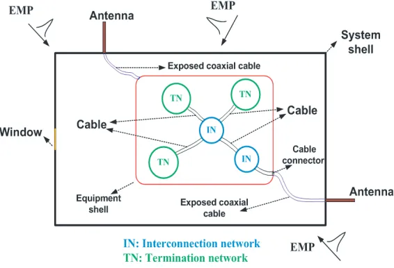
Generally, the cables are connected to termination network or interconnection network consisting of many lumped circuits in electronic information system, as shown in Fig. 2, thus the analysis of the EMC effect for the cable network needs overall consideration to the cable network and circuit loads. The excitation source for the termination network is the voltage or current source introduced from the coaxial cables.
Figure 2. The structure of cable network.
Our method includes three parts: (1) updating the spatial field information by using full wave FDTD method, (2) updating voltage and current for each transmission line, and (3) establishing coupling equations of cables and lumped parameter network according to the Kirchhoff’s law. In step (1), the whole three-dimensional scene will be meshed and simulated by FDTD method, where the transmission line network will be set as thin wire models. By using the Ampere’s law, the 3D field information can be transformed into current source which will be set as the force terms in the telegram equations of the transmission line network. In our method, the FDTD solver for cable calculation and the MNA method for circuit analysis are non-dependent. The two ports equivalent circuit model of the each cable can be described by Fig. 3.
In order to guarantee the consistency of port current and voltage in time and space, equivalent conductanceGeqis added into the circuit network. The equation of source port wherek= 0 is modified as follows:
In+1
S =I n+1/2
SH +GeqVn
+1
0 (13)
where
Geq = Δz
G
2 +
C
Δt
Figure 3. Two-port model of the transmission line circuit model.
In+1/2
SH = 2I n+1/2 1 2
−In S + Δz
G 2 − C Δt Vn 0 (15)
In+1
L = I n+1/2
LH +GeqVn
+1
N (16)
In+1/2
LH = −2I n+1/2
N− 12 −I n L+ Δz
G 2 − C Δt Vn N (17)
The analysis of the multi-port network in each time step can be summarized as
(1) Updating the spatial electric fieldE and magnetic field H, and then transforming them into the current source at the feeding port;
(2) Updating the node voltageVkn+1,(k= 0,1, . . . , N−1) and node currentIkn+1+1//22,(k= 0,1, . . . , N−1) of transmission line by using FDTD method;
(3) Getting the two-port currentISH and ILH from formulas (14) and (16);
(4) Solving circuit equations of interconnection network and terminal network by MNA method; (5) Calculating the port voltage and current.
3. NUMERICAL RESULTS AND DISCUSSION 3.1. Example 1
We firstly consider a transmission line loaded with a 1 pF capacitance, as shown in Fig. 4, which is assumed lossless with distributed parameters L = 250 nH/m and C = 100 pF/m. The exciting signal source is a trapezoidal voltage with its rising edge and falling edge both 0.1 ns, and its voltage amplitude is 1 V with pulse width of 1 ns. 30000 time steps with Δt= 1 ps are carried out in this simulation, and the terminal voltage response Vout is shown in Fig. 5. It can be seen that the calculation results have good numerical stability and meet great agreement by comparing with the PSPICE. It is noted that the accuracy of the results becomes worse at the time range near the falling edge (9 ns) or rising edge (10.2 ns), shown in the zoom of Fig. 5. The reason is that the FDTD method cannot simulate the high frequency components accurately due to the district of its numerical dispersive error.
3.2. Example 2
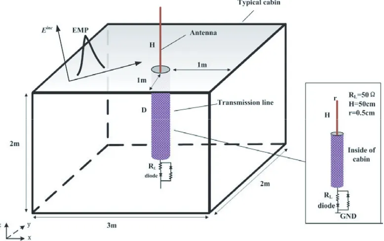
A structure with an antenna on the top of a shelter excited by a lossless transmission line loaded with a complex circuit network, as shown in Fig. 5 is considered in this section. The length D of the transmission line is 1 m. The heightH of the antenna is equal to 50 cm, and the radiusr is 0.5 cm. The impedanceRL is set as 50 Ω. The characteristic of the diode modeled only with nonlinear resistance is described by:
ID =IA(exp(V/VT)−1) (18)
(a) (b)
Figure 4. (a) Transmission line loaded with a capacitance; (b) Comparison of transient voltage responses obtained by PSPICE and FDTD.
Figure 5. Transmission line loaded with nonlinear network in a shelter.
The polarization α is the angle between the direction of electric field and k×z where k is the wave vector andzthe unit coordinate vector. In our FDTD simulation, convolutional perfectly matched layer (CPML) is used as the boundary condition in the solving domain.
Firstly, the method for simulating nonuniform transmission line is applied in obtaining terminal voltage. The uniform transmission line is assumed lossless with L = 250 nH/m and C = 100 pF/m. The nonuniform transmission line is assumed lossless withL= 250/[2 + 0.6 sin(πx/8 +π/4)] nH/m and
C = 100[2 + 0.6 sin(πx/8 +π/4)] pF/m. Both simulators run 10000 times with Δt = 36.5 ps. The result is shown in Fig. 6(b). It is observed that the terminal voltage has great difference between two transmission lines which indicates that the nonuniform characteristic will have a serious impact on signal transmission.
(a) (b)
Figure 6. (a) Gaussian pulse in time-domain; (b) Comparison of terminal voltage transient response for uniform and non-uniform transmission lines.
(a) (b)
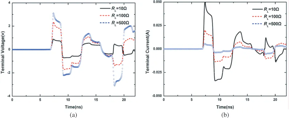
Figure 7. Comparison of transient voltage and current responses loaded with differentRL. (a) Voltage responses; (b) Current responses.
simulation adopts three different loads withRL= 10 Ω, 100 Ω, and 500 Ω, respectively, and the terminal voltage responses of uniform transmission line are shown in Fig. 7(a). It is found that the amplitude of coupling voltage is nearly 3 V which has a serious impact on our circuit. Further, we find that the reflection coefficient is smaller when the nonlinear load impedance is matched with the characteristic impedance of the transmission line. Furthermore, the transient current response of the transmission line is shown in Fig. 7(b). On the contrary, the current reaches its maximum when RL = 10 Ω depending on the volt-ampere characteristic of the circuit loads.
3.3. Example 3
Figure 8. The two-conductor transmission line network.
(a) (b)
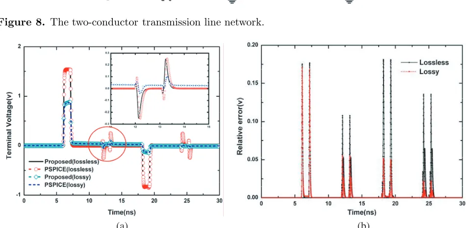
Figure 9. (a) Comparison of the terminal voltage with PSPICE when C1 = 2 pF, C2 = 0.5 pF; (b)
Relative error of lossless and lossy transmission line.
(a) (b)
Figure 10. (a) Comparison of the terminal voltage with PSPICE when C1 = 8 pF, C2 = 1 pF; (b) Relative error of lossless and lossy transmission line.
Figure 11. Two-conductor transmission line network placed inside of the vehicle cabin.
(a) (b)
Figure 12. Comparison of the transmission line terminal response in different polarizations. (a) Voltage response and (b) current response.
For further accuracy comparison between our method and PSPICE, we calculate the relative error, shown in Fig. 9(b), by setting PSPICE as the reference value. The absolute percentage error is less than 1.9% except for some peak points (closed to 1%) for lossless transmission line, and the maximum absolute percentage error is less than 6% for lossy transmission line which provides a good support to verify the accuracy of our method.
Then, we change the capacitance C1, C2 into 8 pF and 1 pF in Fig. 10(a), respectively and
Finally, we put the two-conductor transmission line into a typical cabin, and the structure of the network with parameters marked is shown in Fig. 11. The height H of the antenna is equal to 50 cm, and radius r is 0.5 cm. The capacitance C1 = 2 pF and C2 = 0.5 pF. The incident EMP is selected
as Gaussian pulse propagating along with the direction of θ = 90◦ and ϕ = 45◦. Fig. 12 shows the terminal voltage and current responses in different polarizations α, respectively. It is found that, when the polarization α= 90◦, the voltage and current responses are nearly twice as big as that of α= 45◦. It is because the coupling current from the antenna is the biggest when the antenna and electric field are in the same direction.
4. CONCLUSION
In this paper, a hybrid FDTD method for predicting electromagnetic responses of transmission line with different circuit loads in a vehicle shelter is proposed. Based on full-wave electromagnetic simulation, we can obtain the electromagnetic field distribution of the whole system. Further, the external electromagnetic information can be introduced into the cable network through force current terms based on the equivalent antenna coupling model. MNA method is used to get the equivalent characteristic of the internal circuit which is set as a terminal boundary condition of the transmission line updating equation. Through adopting the antenna coupling model and the transmission line-circuit hybrid model, our simulation method combines the field solver, transmission line solver and circuit model to achieve the field-line-circuit co-simulation of the electronic information system. Its advantage is that the simulation for the whole coupling system is carried out simultaneously at each time step, which provides an accurate and fast solution for such complex cable-loaded EMC/EMI problems. The terminal voltage and current responses have been obtained and compared with the results obtained by PSPICE. The simulation results show that the absolute percentage error is less than 1.9% except for some peak points, which indicates high accuracy of our method. Finally, the proposed method is successfully applied to predict transient responses of a multi-port transmission line network terminated with nonlinear circuits, and further parametric studies are also carried out to show its efficiency and applicability. In fact, our method can be used as a powerful simulation tool for the prediction and analysis to EMC performance evaluation and electromagnetic environmental effects of typical electronic information system designs.
ACKNOWLEDGMENT
This work is supported by the NSFC under Grants No. 61671257, 61631012, and the NSAF under Grant No. U1530121, respectively. It is also sponsored by the K. C. Wong Magna Fund in Ningbo University.
REFERENCES
1. Li, P., Y. Shi, L. J. Jiang, and H. Ba˘gcı, “Transient analysis of lumped circuit networks-loaded thin wires by DGTD method,”IEEE Trans. Antennas and Propagation, Vol. 64, No. 6, 2358–2369, 2016.
2. Carter, N. J., “The past, present and future challenges of aircraft EMC,” IEEE Electromagnetic Compatibility Magazine, Vol. 1, No. 1, 75–78, 2012.
3. Li, P., L. J. Jiang, and H. Bagcı, “Cosimulation of electromagnetics-circuit systems exploiting DGTD and MNA,” IEEE Trans. Components, Packaging and Manufacturing Technology, Vol. 4, No. 6, 1052–1061, 2014.
4. Faghihi, F. and H. Heydari, “Time domain physical optics for the higher-order FDTD modeling in electromagnetic scattering from 3-D complex and combined multiple materials objects,” Progress In Electromagnetics Research, Vol. 95, No. 4, 87–102, 2013.
6. Valente, W., A. Raizer, and L. Pichon, “The use of equivalent model and numerical simulation for EMC analysis in hospital environments,” IEEE Trans. Electromagnetic Compatibility, Vol. 58, No. 4, 1–6, 2016.
7. Baum, C. E., “Electromagnetic topology for the analysis and design of complex electromagnetic systems,”Fast Electrical and Optical Measurements, 467–547, Springer, Netherlands, 1986.
8. Ba˘gci, H., A. E. Yilmaz, and E. Michielssen, “An FFT-accelerated time-domain multi-conductor transmission line simulator,” IEEE Trans. Electromagnetic Compatibility, Vol. 52, No. 1, 199–214, 2010.
9. Ba˘gci, H., A. E. Yılmaz, J. M. Jin, and E. Michielssen, “Fast and rigorous analysis of EMC/EMI phenomena on electrically large and complex cable-loaded structure,”IEEE Trans. Electromagnetic Compatibility, Vol. 49, No. 2, 361–381, 2007.
10. Wang, W., P. G. Liu, and Y. J. Qin, “An unconditional stable 1D-FDTD method for modeling transmission lines based on precise split-step scheme,” Progress In Electromagnetics Research, Vol. 135, No. 1, 245–260, 2013.
11. Tatematsu, A., “A technique for representing coaxial cables for FDTD-based surge simulations,” IEEE Trans. Electromagnetic Compatibility, Vol. 57, No. 3, 488–495, 2015.
12. Boutar, A., A. Reineix, C. Guiffaut, and G. Andrieu, “An efficient analytical method for electromagnetic field to transmission line coupling into a rectangular enclosure excited by an internal source,” IEEE Trans. Electromagnetic Compatibility, Vol. 57, No. 3, 565–573, 2015.
13. Wang, J., Y. S. Xia, and L. Y. Wang, “Electromagnetic responses of a metallic conical frustum cabin with one coaxial feeding monopole antenna,”Int. Journal of Applied Electromagn.&Mechan., Vol. 47, No. 3, 765–776, 2015.
14. Wang, J., W. Y. Yin, and J. P. Fang, “Transient responses of coaxial cables in an electrically large cabin with slots and windows illuminated by an electromagnetic pulse,” Progress In Electromagnetics Research, Vol. 106, No. 9, 1–16, 2010.
15. Mao, Y., B. Chen, H. Q. Liu, J. L. Xia, and J. Z. Tang, “A hybrid implicit-explicit spectral FDTD scheme for oblique incidence problems on periodic structures,”Progress In Electromagnetics Research, Vol. 128, No. 14, 153–170, 2012.
16. Ye, Z., C. Liao, and X. Xiong, “The research and application of a novel time domain hybrid method for EMI analysis of lumped circuits in a shielded device,” IEEE Trans. Electromagnetic Compatibility, Vol. 58, No. 4, 964–970, 2016.
17. Liu, Q. F., W. Y. Yin, M. Tang, P. Liu, J. F. Mao, and Q. H. Liu, “Time-domain investigation on cable-induced transient coupling into metallic enclosures,” IEEE Trans. Electromagnetic Compatibility, Vol. 51, No. 4, 953–962, 2009.
18. Hyun, S. Y., S. Y. Kim, and Y. S. Kim, “An equivalent feed model for the FDTD analysis of antennas driven through a ground plane by coaxial lines,”IEEE Trans. Antennas and Propagation, Vol. 57, No. 1, 161–167, 2009.
19. Vlach, J. and K. Singhal, Computer Methods for Circuit Analysis and Design, Springer Science & Business Media, 1983.