172 | P a g e
VIBRATION TESTING AND PERFORMANCE
ANALYSIS OF IC ENGINE EXHAUST VALVE USING
FINITE ELEMENT TECHNIQUE
Mamta R. Zade
1, Prof. M.J Sature
2,
1,2
Mechanical Engg . Department ,GSMCOE Balewadi Pune (India)
ABSTRACT
During running condition of engine it allows the burned gasses to go out in the environment through the silencer.
Hence the engine valve operated at high pressure and temperature. Also the very important part of its movement is
that, it should operate within a fraction of second so as to allow burned mixture to go out. The vibrations at a
particular frequency range also can create the resonance phenomenon which can also cause damage of valve.
Hence the study of vibrations set up in the valve is very important. In this paper we are testing vibration effects on
IC engine exhaust valve and also finding out the natural frequency of valve to identify the resonance phenomenon
frequency level. The obtained results and effects are illustrated further so as to prevent valve damage. To perform
overall process. Finite Element Technique is very useful and convenient which provides better approximate solution.
Exhaust valves are exposed to thermal stress more than intake valve because intake valve are virtually cooled by
fresh air. However burnt gases have very high temperature in the range of 800 to10000C because of this frequency
of failure of exhaust valve is higher than inlet valve.
Keywords: Exhaust Valve ,CatiaV5, Ansys14.5
I. INTRODUCTION
Two stroke engine valves operated at high loading condition. Due to this failure chances are more. So it needs
regular inspection and maintenance so as to reduce failure chances. Hence the operating cost will gate reduced and
the life of component is more. Wear effects will produce various issues related to failure, but due to regular
inspection and maintenance we are able to increase the life of component. As the valve material is hardest and
having good working properties, there are less chances of damage due to the resonance effect. But we know that
exhaust valve operates at high temperature and hence at high working temperature there are chances of losing the
properties and may get damaged due to vibration. The vibrations are specified in the form of frequency in this paper.
The study illustrates the effects of vibration on exhaust valve at high temperature.
II. LITRATURE SURVEY
Following litratures are studied ,
[1] Nurten VARDAR, Ahmet EKERİM Investigation of Exhaust Valve Failure in Heavy – duty Diesel Engine
Yildiz Technical University, Faculty of Mechanical Engineering, 34349 Istanbul, Turkey Received: 25.08.2009
Revised: 23.10.2009 Accepted: 13.11.2009
[2]Naresh Kr. Raghuwanshi, Ajay Pandey, R. K. Mandloi Failure Analysis of Internal Combustion Engine Valves:
173 | P a g e Mechanics, M.A.N.I.T., Bhopal, Madhya Pradesh, India1
[3]Miroslaw Wendeker, Pawel Magryta,Adam Majczak, Michal Bialy Modeling the thermal loadsnin the SUBARU
EJ25 Engine Lublin University ofb Technology, Nadbystrzycka Street 36/605A, 20- 618 Lublin, Poland, email:
[email protected], mJournal of KONES Powertrain and Transport, Vol. 18, No. 1 2011
[4] A. Hornik, D. Jędrusik, K. Wilk Unsteady state heat flow in the exhaust valve in turbocharged Diesel engine
covered by the layer of the carbon deposit Department of Automotive Vehicle Service, Faculty of Transport, Silesian
University of Technology, ul. Krasińskiego 8, 40-019 nKatowice, Poland, International Scientific Journal published
monthly by the World Academy of Materials and Manufacturing Engineering,
Received 05.02.2012; published in revised form 01.04.2012
[5] M. Azadi1*, M Roozban2, A. Mafi ,Failure analysis of an intake valve in a gasoline engine
Fatigue and Wear Workgroup, Irankhodro Powertrain Company (IPCO), Tehran, Iran,
[email protected] The Journal of Engine Research, Vol. 26 (spring 2012), pp. 03-09
[6] Dr. Ing. Holger Fellmann,Typical wear mechanism of 2-stroke exhaust valves Head of2-
stroke department & service; Märkisches Werk GmbH Royal Belgian Institute of Marine Engineers, Marine
Propulsion conference 2012.
III. MODES OF FAILURES OF VALVES
Following are different types of failure and their causes of inlet & exhaust valve.
Failure Due to Fatigue
The meaning of word fatigue means “to tire” which is derived from latin word “Fatigue”. In engineering
language/terminology fatigue failure is a progressive structural damage of the material of the component when the
component under goes cyclic loading. There are two important categories of fatigue failure a) Mechanical failure
due to fluctuating stresses due to cyclic load at high temperature. b) Thermal fatigue due to cyclic changes in
component material temperature.
3.2 Failures Due to High Temperature
Exhaust valves operate at very high temperatures usually above 6000 C and are subjected to cyclic loading. The
failure of the conical surface/sealing area of valve is mainly caused by the elastic and plastic deformation. Exhaust
valve stem generally fails by overheating because the temperature of the exhaust valve is about 600 ºC. The fracture
surface of the valve stem is covered with a black oxide scale formation. Fracture surface in the fatigue area is
smooth and is covered with thick oxide or deposits that cannot be removed satisfactorily.
Failure of Valve Due to Erosion-Corrosion
Surface material is removed in service life and it is the result of erosion by small, solid, impacting particles. In most
elevated - temperature erosion environments, the eroding surface is undergoing corrosion as well as erosion. In one
test series, a nickel oxide scale was formed up to 100 μm thick at1000ºC on commercially pure nickel
Failure of Valve Due to Vibrational Effects
Exhaust valves are exposed to thermal stress more than intake valve because intake valve are virtually cooled by
fresh air. However burnt gases have very high temperature in the range of 800 to10000C because of this frequency of
174 | P a g e
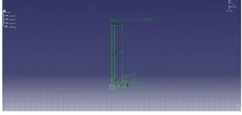
Fig.3 Geometry of Valve
IV. VALVE MODELING PROCESS BY CATIA SOFTWARE
There are several CAD software are available for 3D modeling. To model the exhaust valve we have chosen CATIA
V5.
Fig. 4 : Sketch in CATIA
4.1 3D Model of Trapozoidal Section
175 | P a g e
V. PERFORMING VIBRATION ANALYSIS
To perform vibration analysis on exhaust valve we have to go through the model analysis with FEA software.
Vibrations set up in valve can be measured in Hz with its maximum deformation values in mm. Model analysis is
nothing but an vibration analysis where the vibrations are measured in the form of frequency range set up in valve
during vibrations.
Here ANSYS is the FEA package that we are using for performing vibration analysis over exhaust valve.
VI. VALVE MATERIAL
While performing analysis on valve we need to assign initial and boundary conditions of valve. The material
properties of valve are the important factors for performing vibration analysis. Due to hardness at room temperature
(50 Rockwell C) for Steel alloys with a martensitic grain structure after tempering, properties like strength, wear
resistance improve extensively. Such characteristics of valve material are good for long life of valve with efficient
performance and high corrosion resistance.
6.1 Material Properties Of Structural Steel
A shank end of crane hook is fixed and a loads are applied on bunch of nodes at lower centre of hook in downward
direction. A load of 1ton (9806N) is taken for analysis. First material selected for crane hook is Structural Steel and
the properties of material are given below:
Structural Steel > Constants
Density 7850kgm^-3
Coefficient of Thermal
Expansion
1.2e-005C^-1
Specific Heat 434Jkg^-1C^-1
Thermal Conductivity 60.5Wm^-1C^-1
Modulus of elasticity 2.5e05Mpa
Poissons Ratio 0.3
Structural Steel>Tensile Yield Strength
Structural Steel > Tensile Ultimate Strength
Chemical Composition of Structural Steel Reference Temperature C
22
Tensile Ultimate StrengthPa 4.6e+008
Tensile Yield Strength Pa
176 | P a g e
Element Content (%)
Vanadium,V 0.03-0.08
Carbon, C 0.15-0.30
Phosphorus,P 0.04-0.05
Silicon, S 0.02-0.4
Nickel,N 0.25-1.25
Mangnese, Mn 0.50-1.70
Maximum Nodes = 12180
Maximum Nodes = 7499
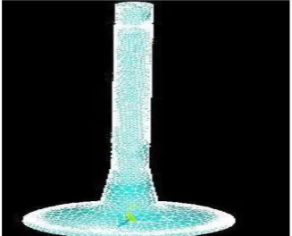
VII. MESHING OF EXHAUST VALVE
Meshing is nothing but converting entire object into small number of pieces which are connected to each other by
means of connecting points. Each small piece of an object is called as element and the connecting points are called
as nodes. It is one of the important step in FEA to carry out required solution. For generation of meshing of exhaust
valve we are 3D tetrahedron element. This process is also called discretisation process. Following figure 2 shows the
meshed view of an exhaust valve. using Exhaust vale meshing details with respect to nodes and elements.
Maximum Nodes = 18015
Maximum Elements = 87269
Figure 6: Meshed view of exhaust valve.
VIII. INITIAL AND BOUNDARY CONDITION FOR EXHAUST VALVE
Constraining of valve for vibration analysis is done by applying initial and boundary conditions. Valve geometry is
constrained at the top in all directions. In vibration analysis vibration modes can be simulated by applying density
value and other property values. Five modes of frequencies are obtained in vibration analysis after applying initial
177 | P a g e
IX. GENERATION OF VIBRATION ANALYSIS SOLUTION
Solution for vibration analysis is obtained with five different mode sets and their respective deformations. Each
mode specifies the vibration range in the form of frequency and maximum deformation at that frequency level. FEM
technique is used to find out these mode frequencies. FEA tool is used for that purpose. Calculated results are
studied to obtain conclusions. Maximum deformation is observed in the valve at the fifth mode of vibration. Here the
frequency value is also greater than other frequency values in different modes. And this maximum
frequency value also called natural frequency of exhaust valve. Exhaust valve may damage due to high vibrations at
resonance frequency value which slightly greater than natural frequency of exhaust valve.
X. ANALYSIS RESULTS
The maximum value of frequency is 1511.3 Hz is obtained while performing vibration analysis on exhaust valve.
This is the natural frequency value for exhaust valve. Above this value resonance phenomenon will accurse. All the
frequency values are tabulated in following table for various modes of frequency.
Table:1 Frequency values and their deformationfor each set
SET FREQUENCY LOADSTEP SUBSTEP
1 139.635 Hz 1 1
2 139.99 Hz 1 2
3 845.76 Hz 1 3
4 1502.2 Hz 1 4
5 15011.3 Hz 1 5
XI. MODES AND VIBRATIONS
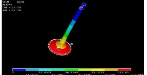
11.1 Mode One Vibrations
In this mode the observed frequency value is 139.635 Hz with maximum deformation 128.058mm. The deformation
is observed at the bottom side of the valve. But as this portion is placed on valve sheet, this deformation is reduced.
178 | P a g e
11.2 SECOND MODE OF VIBRATION:
In this mode the deformation is reduced with negligible increment in frequency. The frequency value is observed to
139.986 Hz with deformation 128 mm. This deformation and frequency will not affect performance of valve.
Figure 8: Second mode of vibration with maximum deformation
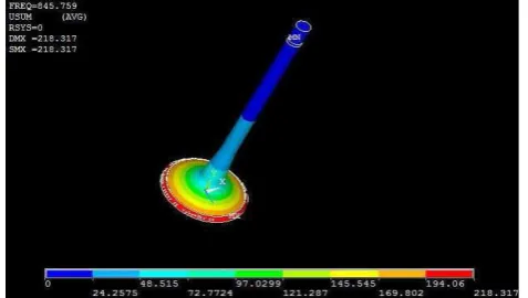
11.3 Mode Three of Vibration:
In this mode frequency suddenly increases with value 8 45.759 Hz with maximum deformation 218.317 mm. This
deformation is large with frequency. But it is maximum allowable deformation. In actual condition there will not be
such large deformation because of
constraints available
Figure 9: Third mode of vibration with allowable deformation.
11.4 Mode Four Of Vibration:
Here also the frequency value increases. But increment is large with reduction in deformation.
Maximum value of frequency is 1502.24 Hz with deformation of 203.93 mm. In this mode deformation is reduced as
179 | P a g e
Figure 10: Fourth mode of vibration with frequency and deformation
11.5 Mode Fifth Of Vibration:
In this mode maximum deformation is 203.95 mm with maximum frequency 1511.34 Hz. Above this value valve
may damage. Stem of valve is most affected zone. This maximum frequency is natural frequency of valve.
Figure 11: Maximum frequency with maximum deformation
RESULT
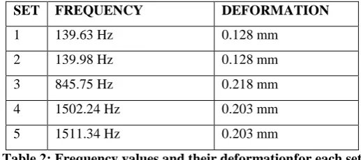
SET FREQUENCY DEFORMATION
1 139.63 Hz 0.128 mm
2 139.98 Hz 0.128 mm
3 845.75 Hz 0.218 mm
4 1502.24 Hz 0.203 mm
5 1511.34 Hz 0.203 mm
Table 2: Frequency values and their deformationfor each set
Below table have frequency values and deformations for each mode of vibration.
XII. CONCLUSIONS
By studying all five modes of vibrations we can conclude following points.
1. Deformation and frequency value in first and second mode of vibration is approximately same.
2. Deformation is large in all modes of vibration and needs to reduce.
3. Maximum frequency of valve provides better stability.
180 | P a g e 5. Exhaust valve have a good frequency but deformation needs to reduce.
REFERENCES
[1] Nurten VARDAR, Ahmet EKERİM Investigation of Exhaust Valve Failure in Heavy – duty Diesel Engine
Yildiz Technical University, Faculty of Mechanical Engineering, 34349 Istanbul, Turkey Received:
25.08.2009 Revised: 23.10.2009 Accepted: 13.11.2009
[2] Naresh Kr. Raghuwanshi, Ajay Pandey, R. K. Mandloi Failure Analysis of Internal Combustion Engine
Valves: A Review Department of Applied Mechanics, M.A.N.I.T., Bhopal, Madhya Pradesh, India1
[3] Miroslaw Wendeker, Pawel Magryta,Adam Majczak, Michal Bialy Modeling the thermal loadsnin the
SUBARU EJ25 Engine Lublin University ofb Technology, Nadbystrzycka Street 36/605A, 20- 618 Lublin,
Poland, email: [email protected], mJournal of KONES Powertrain and Transport, Vol. 18, No. 1 2011
[4] A. Hornik, D. Jędrusik, K. Wilk Unsteady state heat flow in the exhaust valve in turbocharged Diesel engine
covered by the layer of the carbon deposit Department of Automotive Vehicle Service, Faculty of Transport,
Silesian University of Technology, ul. Krasińskiego 8, 40-019 nKatowice, Poland, International Scientific
Journal published monthly by the World Academy of Materials and Manufacturing Engineering, Received
05.02.2012; published in revised form 01.04.2012
[5] M. Azadi1*, M Roozban2, A. Mafi ,Failure analysis of an intake valve in a gasoline engine Fatigue and
Wear Workgroup, Irankhodro Powertrain Company (IPCO), Tehran, Iran, [email protected] The Journal
of Engine Research, Vol. 26 (spring 2012), pp. 03-09
[6] Dr. Ing. Holger Fellmann,Typical wear mechanism of 2-stroke exhaust valves Head of2- stroke department
& service; Märkisches Werk GmbH Royal Belgian Institute of Marine Engineers, Marine Propulsion
conference 20 12
BIBLOGRAPHY
Ms. Mamta R. Zade P.G. Student at Dept. of Mechanical Engg.
GSMCOE Balewadi Pune-45.She has received the Bachelor of Engineering. in Mechanical
branch from the Nagpur University , India, in 2012 Specialization/ Interested Area: Design
Engg. Email Adress: [email protected]
Prof. Manoj J. Sature born in Osmanabad town Maharashtra India, in 08/02/1984 He has received the Bachelor of Engineering. in Mechanical branch from the Dr.Babasaheb
Ambedkar Marathwada University ,Aurangabad , India, in2006and M.Tech Degree in
Design Engineering from C.O.E.P.,Pune university, India, in 2013. He is working as Assistant professor in Mechanical Engineering Dept. of GS Moze College of Engineering