321 |
P a g e
ADJUSTABLE GROUND CLEARANCE MECHANISM
Shivaraj Chandrakant Patil
Student at Department of Mechanical Engineering, University of Pune, PGMCOE, (India)
ABSTRACT
Suspension is one of the mostchallenging systems to design for off-road vehicle. Proper suspension mechanism and respective parameters are important for off-road vehicles. The suspension design should be adaptable to changing road conditions. The designers prefer to maintain fixed ground clearance and design the system to acquire satisfactory suspension parameters. The road vehicle should not be treated the same way. Most of the time off-road vehicles have to face the rough terrain, where we need high ground clearance of the vehicle. On the other hand, we also run the same vehicle on a terrain where high ground clearance is not necessary. It is noticeable that with the higher ground clearance, we can’t utilize the full potential of acceleration as compared to at the lower ground clearance.
During running condition of vehicles, location of the center of gravity (C.G) is also an important parameter. For better handling of the vehicle we need to keep C.G point as low as possible. This is possible by adjusting the ground clearance of the vehicle. Hence, I utilize the concept of Adjustable Ground Clearance Mechanism which will prove beneficial effect to the off-road vehicles to adjust the ground clearance according to terrain.
Keywords
:
Innovative concept, Adjustableground clearance, Off-road vehicles, suspension
parameters, Weight Transfer, Accelerating, and Cornering Effect.
I INTRODUCTION
Ground clearance is the position of the vehicle body (sprung mass) above the basic ground level.
It’s an important parameter in off-road vehicle. For a certain car’s weight, there is a certain amount of mechanical down force act on tires, and therefore the grip of tires is constantly changing during running condition. The whole weight of vehicle is concentrated at a point known as a center of gravity point. The center of gravity of a vehicle is calculated by taking the sum of its moments divided by the overall weight of the vehicle. The moment is the product of the weight and its location as measured from a set point called the origin.
322 |
P a g e
a location of C.G point at a high level as well as at lower level according to road conditions.
I designed a simple mechanical linkage mechanism for ground clearance adjustment. The adjustment is possible at droop conditions with the help of small gear. With the help of this system we can vary ground clearance of the vehicle up to 180mm. The system consist a new fabricated shock absorber mounting bracket. One of the bracket plates has the required tooth to mesh with the gear. We can adjust the ground clearance of our vehicle in four different stages with different ground clearance.
II DESIGN AND CONSTRUCTION
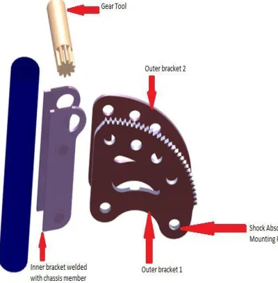
It involves the use of a small gear as a tool to move toothed bracket which holds the shock absorber. This toothed bracket is in the shape of a circular arc. The nomenclature of the Adjustable Ground Clearance Mechanism is, as mentioned below:
Fig. 2.1 Nomenclature of System
Shock absorber mounting brackets with following specifications
Two outer brackets: outer toothed bracket 1 and outer bracket 2.
Two inner brackets: Inner bracket 1 and inner bracket 2
A small gear with the following specifications is used:
O.D. = 18mm
I.D. = 11.7mm
No. Of Teeth = 10
Module = 1.5mm
P.C.D. = 15mm
323 |
P a g e
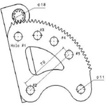
According to this gear, the shock absorber mounting bracket 1 was fabricated to mesh with this gear. To ensure this bracket were fabricated by LASER Cutting Machine. The other plate was without any teeth as shown in diagram.
Fig.2.2 Drafting of designing toothed bracket
The assembly consists of two inner brackets which are welded to the chassis. These inner brackets have three holes. The lower two holes are used for bolting the outer bracket as shown.
324 |
P a g e
III WORKING
The outer brackets consist of 6 holes. The lower hole is used for shock mounting as shown in figure. Once bolted, it is not altered frequently. The outer bracket is bolted as two points in the inner bracket, i.e. hole-1 and hole-2. The bracket has three additional holes which are used for variable ground clearance adjustment. To adjust the ground clearance the hole-1 bolt is removed and hole-2 bolt is loosened, now the gear tool is inserted in the inner bracket and it engages with the outer bracket as shown in fig. 2.3. A lever or a spanner is used at the head of the gear tool. Now the gear is rotated in such a way that hole-3 matches with the hole of inner bracket, thus the ground clearance is lowered by 60mm. Now the bolt is inserted in the hole-3 and tightened and the other bolt is also tightened.
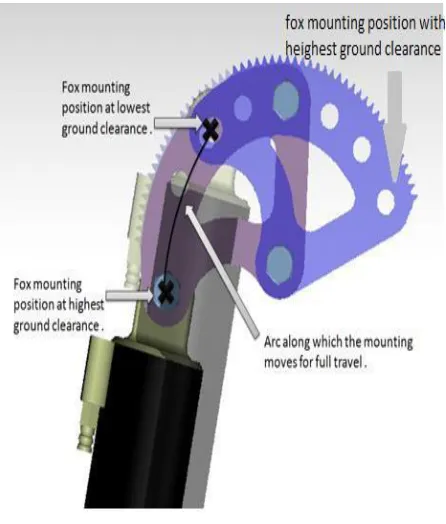
Therefore, we have got total three steps for ground clearance adjustment. In each step, ground clearance is lowered by 60mm, thus in all the total ground clearance gets lowered by 180mm.
Fig. 3.1 Stepwise change
Table: Stepwise change in Ground Clearance
Sr. No. Ground Clearance Hole #1 360mm Hole #3 300mm Hole #4 240mm Hole #5 180mm
325 |
P a g e
In this way, by this mechanism, we can have a maximum ground clearance of 360mm for all off-road applications and a minimum ground clearance of 180mm for on road applications. The design and construction of the adjustable ground clearance mechanism aim at changing ground clearance in the range of 180mm with good vehicle dynamic behavior. In order to achieve this goal through a study of force required to adjust the holes is essential. Also, we have to analyze the whole system in dynamic conditions. Here are some results of analysis conducted in ANSYS14.0 software.
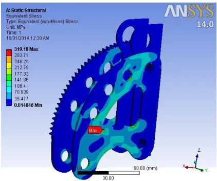
Fig. 3.2 Static Structural Analysis
3.1 Results:
Boundary conditions: Force on front and rear shocks = 4G.
Where, G =Sprung mass of vehicle× acceleration due to gravity (9.81m/s2) F = 4× 200× 9.81
F = 7848 Nm
Maximum equivalent stress = 319.1Mpa. Fatigue Factor of Safety = 1.3. Maximum deformation = 0.003mm.
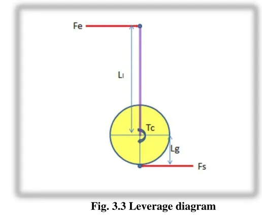
3.2 Operational Efforts Required
Table: Leverage Force
Parameters Value Shock absorbers force (Fs) 1962N
acting on the center of the pinion
Radius of pinion gear (Lg) 9mm Torque is acting on the center 17658Nmm
of the pinion (Tc)
Leverage 1:22
326 |
P a g e
Fig. 3.3 Leverage diagram
IV ADVANTAGES
This innovation can help driver to choose the ground clearance with his comfort of driving according to terrain.
Riding off-road becomes easier and vehicle can be fuel efficient by lowering ground clearance while driving on-road.
For the off-road tracks, one can have highest ground clearance and move along the course of the roads with better handling. On other hand for on-road tracks, by lowering ground clearance we can enjoy the pleasure of being in an on-road vehicle.
This system helps in under steering of the vehicle.
The system is very user friendly.
V DISADVANTAGES
There is need to lift the vehicle while changing the position of the brackets.
VI CONCLUSION
The system proves that the Adjustable Ground Clearance Mechanism is a good innovative system for better performance of off-road vehicles. Since the system is more users friendly and at the same time increase the efficiency of performance, this will have good market potential. The ground clearance can be easily adjusted by the driver itself at any place. The system is very much reliable in operation. The simulation results show that the system remains in the stable range of parameters and does not hamper any performance variable.
327 |
P a g e
initial as well as running costs. It does not require an external energy sources to run the system and no moving parts in the system so maintenance is also very low. We also conclude that due to the system, suspension parameters are amplified remarkably. Also, the system is cheaper and eco-friendly method is developed.
REFERENCE
[1]S. S. Sabharwal, Automobile Engineering (BE Mechanical, Semester- I, University of Pune; September 2012. Chapter - 7 Suspension Systems.)
[2]RAJPUT R.K ,Strength of Material (S. Chand and company LTD; 2010.) pp. (928-941, 590-592,264-265).
[3] Don Knowles, Automotive Suspension and Steering Classrom Manual (2010. Chapter -5, 6, 7)
[4]David H. Myszka, Mechanics and Mechanism, Applied Kinematic Analysis (4th Edition (Gear Design) Chpater - 1, 2, 5, 10, 13, 14)
[5]www.wikipiedia.org/suspensiondesign.