University of South Carolina
Scholar Commons
Theses and Dissertations
5-2017
Bird's Eye View: Cooperative Exploration by UGV
and UAV
Shannon Hood
University of South CarolinaFollow this and additional works at:https://scholarcommons.sc.edu/etd Part of theComputer Sciences Commons, and theEngineering Commons
This Open Access Thesis is brought to you by Scholar Commons. It has been accepted for inclusion in Theses and Dissertations by an authorized administrator of Scholar Commons. For more information, please [email protected].
Recommended Citation
Bird’s Eye View: Cooperative Exploration by UGV and UAV
by Shannon Hood
Bachelor of Science
University of South Carolina 2016
Submitted in Partial Fulfillment of the Requirements for the Degree of Master of Science in
Computer Science and Engineering College of Engineering and Computing
University of South Carolina 2017
Accepted by:
Ioannis Rekleitis, Director of Thesis Marco Valtorta, Reader
Jason O’Kane, Reader
c
Acknowledgments
Abstract
Table of Contents
Acknowledgments . . . iii
Abstract . . . iv
List of Figures . . . vii
Chapter 1 Introduction . . . 1
Chapter 2 Related Works . . . 6
2.1 Robot Collaboration . . . 6
2.2 Tag Tracking . . . 7
2.3 Monocular SLAM . . . 10
2.4 Cooperative Localization . . . 11
Chapter 3 Approach . . . 13
3.1 Robot Team Network . . . 13
3.2 Movement of the UGV . . . 15
3.3 Tag Detection & Movement of the UAV . . . 16
3.4 Cooperative Localization . . . 18
3.5 UAV Localization Using ORB-SLAM . . . 20
Chapter 4 Results . . . 23
Chapter 5 Conclusion . . . 29
Bibliography . . . 31
Appendix A Platform Documentation . . . 36
A.1 Software Installation . . . 36
A.2 Robot Initialization . . . 40
A.3 Controlling the Robots . . . 43
A.4 Sensors and Actuators . . . 45
A.5 Shutting Down . . . 47
List of Figures
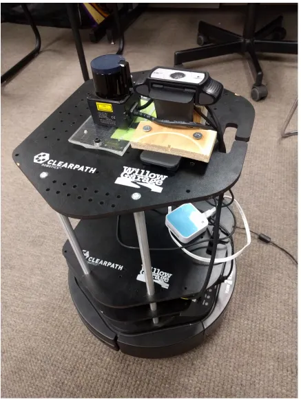
Figure 1.1 The Kobuki TurtleBot 2 used in this thesis. Also seen are the
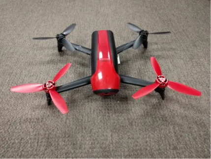
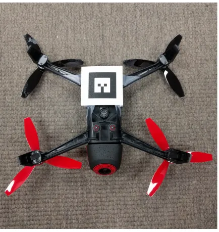
Hokuyo laser, TurtleBot camera, and router used. . . 3 Figure 1.2 The Parrot Bebop 2 used in this thesis. . . 4 Figure 1.3 A fiducial tag attached to the bottom of a Parrot Bebop 2. . . 5
Figure 2.1 An example of a QR code is shown to the left, while two fiducial
tags generated by ar_track_alvar are shown on the right. . . 8
Figure 3.1 Shows the network connections between the ground Control Station (GCS), the TurtleBot, and the Bebop. Connections are
shown in blue. . . 14 Figure 3.2 An example of a random walk motion algorithm showing laser
scans and odometry data in rviz. . . 15 Figure 3.3 Early UAV camera feeds: In the left image, the bottom camera
observes the tag placed on top of the UGV. The right image
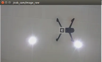
shows the front camera view with PTAM detected features overlayed. 17 Figure 3.4 Bebop 2 flying over the UGV with a tag. . . 17 Figure 3.5 Shows the relationships between different odometry and
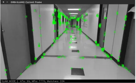
local-ization methods used. . . 19 Figure 3.6 Shows the Bebop’s front camera view with ORB-SLAM features
overlayed in green. . . 20
Figure 4.1 Early Experiments with the AR.Drone 2.0. Shows a 2-dimensional
map of the environment and path taken by the robots. . . 24 Figure 4.2 Traversing down the corridor with the walls mapped. The UGV
Figure 4.3 Random walk experiment with the walls mapped. The UGV
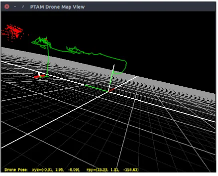
trajectory is shown in blue and the UAV trajectory, above, in pink. 26 Figure 4.4 Center-of-the-corridor ORB-SLAM experiments: (a) The left
image shows a map of features and keyframes generated by ORB-SLAM. (b) In the right image, the UGV trajectory is shown in blue, the UAV trajectory as calculated by CL in pink,
and the UAV trajectory according to ORB-SLAM in green. . . 27 Figure 4.5 Traversing Swearingen’s 3rd floor with the walls mapped. The
UGV trajectory is shown in blue and the UAV trajectory, above,
in pink. . . 27
Chapter 1
Introduction
With the proliferation of unmanned air vehicles (UAVs) a new viewpoint, a birds-eye-view, has become available in many domains, allowing structure inspection, envi-ronmental monitoring, virtual tourism, and search and rescue. The majority of aerial vehicles are severely limited in the sensing payload they can carry due to weight constraints. As such, simple tasks such as obstacle avoidance and localization in an unknown environment become rather challenging. On the other hand, ground robots, while extremely capable in navigating safely inside an unknown environment, are re-stricted to a limited field of view. Deploying a robot team comprised of a ground and an aerial vehicle enables an enhanced field of view while maintaining safe navi-gation and localization. Recent advances in robotics have made collaboration among a heterogeneous team of robots possible [39]. At the same time, many interesting problems associated with multi-robot collaborative exploration are being discussed, such as coordination, communication protocols, bandwidth constraints, etc. [24, 42]. One motivating application is search and rescue in a damaged building, where the UGV navigates on the ground while the UAV maintains a fixed pose above the UGV employing a robot-tracker sensor consisting of a camera and fiducial marker. The robot team could search and map dangerous areas, monitored by a remote operator at a safe distance. 1
The goal of this thesis is to present a collaborative exploration approach
utiliz-1Early parts of this work have been submitted jointly with Kelly Benson, Daniel Madison, Patrick
ing a UGV and a UAV. The UGV, a Kobuki TurtleBot 2 equipped with a Hokuyo laser range finder and an upwards-facing camera, is responsible for guiding the UAV through the corridors of a building; see Fig. 1.1. The UAV, a Parrot Bebop 2 equipped with a forward facing camera, provides enhanced situational awareness to a remote expert; see Fig. 1.2. The UAV does not process all data and commands on-board. Instead, utilizing a WiFi connection, the sensor data are transmitted to a ground station where all the processing takes place. Currently we utilize two computers: one on the UGV and a separate one as a ground control station (GCS). A unique fiducial tag placed on the bottom of the UAV is tracked by a wide angle camera on top of the UGV, and the relative pose between the two vehicles is estimated.
Using cooperative localization, the pose of the UAV is calculated using the Turtle-Bot’s pose and the relative pose of the two robots. This calculated pose is compared to the pose provided by ORB-SLAM2 [29], a monocular SLAM package run using data provided by the UAV’s camera. These two localization techniques improve the accuracy of UAV’s estimated pose, allowing for easier path planning and tracking of the tag.
Chapter 2
Related Works
Cooperative robotics has been explored as early as the 90’s, such as when Cao et al. [4] discussed possible future applications and the open problem of collaboration between autonomous robots. Yuta and Premvuti [43] discussed how to organize multiple autonomous robots. Several previous experiments have examined the best software for tag tracking, autonomous communication between robots, or have used similar setups involving both a ground and an aerial based robot. Collaboration between UGVs and UAVs has been proposed for a variety of fields. For example, in the detection and fighting of wildfires [32], in measuring the amount of nitrogen in the soil for agricultural applications [41], for surveillance [17], and for detecting and disposing of mines [10]. UAVs have also been used to monitor traffic [20].
2.1 Robot Collaboration
Chaimowicz and Kumar [5] discussed ground robot and aerial robot localization in their 2007 paper. Their research focused on environments with limited GPS access, and on using GPS in conjunction with other sensors. Similar concerns also drove the work of Frietsch, Meister, Schlaile, and Trommer [15]. However, unlike these two previous works, the approach proposed by this thesis assumes no GPS access, instead relying on cooperative localization [36] between the two vehicles as well as pose estimates calculated from the laser scan and cameras.
"Multi-domain monitoring of marine environments using a heterogeneous robot team," Shkurti et. al. used underwater vehicles, airboats, and aerial vehicles to autonomously col-lect footage of underwater scenes. In Murphy’s experiment, the robots were used to survey storm damage from Hurricane Wilma. It was also "the first known use of unmanned sea surface vehicles (USVs) for emergency response" [30].
MacArthur and Crane [25] investigated using a UAV in the state estimation of a UGV. In their paper, they discuss camera calibration and extracting pose from camera data, as well as the coordinate transforms needed. Unlike with this project, GPS was integrated with pose information. MacArthur and Crane found that localization of a UGV using a passive UAV was successful in both simulated and experimental runs.
Cooperation between UAVs and UGVs for target detection and formation holding was proposed by Tanner [40]. Duan and Liu [9] discuss an overview of multiple vehi-cles collaborating with a focus on military applications. Papachristos and Tzes [31] proposed a tethered solution to address the limited battery time for longer opera-tions. Autonomous landing on a UGV charging station was proposed by Rezelj and Skocaj [37].
2.2 Tag Tracking
faster. This faster computation is possible because ar_track_alvar is initialized with the size of the tag to help it better determine the position of the tag relative to the frame given. In this experiment, Minhua and Jiantao modified the front camera of the drone to point towards the ground for better tag tracking because the front camera has a higher resolution [28]. They also experimented with using
ar_track_alvar in conjunction with tum_ardrone, a wrapper for PTAM (Parallel
Tracking and Mapping) and PID controller for the drone, when they were landing the AR.Drone on a tag. They found that usingar_track_alvar to find the tag and
tum_ardronefor the PID controller to move the UAV into position of the tag landing
zone worked fairly well [28].
Figure 2.1 An example of a QR code is shown to the left, while two fiducial tags generated by ar_track_alvar are shown on the right.
Another example of previous work related to autonomous flight is the experiment by Rezelj and Skocaj focused on landing a modified AR.Drone on a TurtleBot with an augmented reality tag, so that the drone could charge and then take off again by making use of the ground vehicle’s longer battery life [37].
Lawrence and Turchina [23] evaluated different approaches to fiducial tag track-ing. In their experiments on pose estimating software packages, they found that
ar_track_alvarwas the best package for estimating the pose of a tag from the frame
of a camera. Packages they tried include: ar_sys, ar_pose, visp_auto_tracker,
and ar_track_alvar. However, not all of them work with ROS and some require a
wrapper. Due to time constraints, and the fact that ar_pose was not available in ROS, they did not test it extensively. It is also important to note that the camera they used to test the packages had a resolution of 640x480, while our tracking camera has a resolution of 1920x1080. The higher resolution of the Bird’s Eye View cam-era allows for better tag tracking, since the tag can move farther distances and still remain within view of the camera. The next tested package, ar_sys, gave a range of 30cm to 120cm at 30hz. Unfortunately, with our camera’s resolution, this would require the UAV to fly too close to the UGV. The next package,visp_auto_tracker, had a range of 60cm to 300cm at 30hz. One major drawback of this package was that if the UAV lost sight of the tag, it needed to re-establish at the minimum distance to continue tracking. Thus with this package, any time the tag was lost the UAV would have to maneuver to a precise location to reinitialize the tracking. Lastly, Lawrence and Turchina tested ar_track_alvar, which ran from 30cm to 300cm at 10hz. This package had the best range for establishing tracking and is what this project will use. One problem of tag tracking software, in addition to range limitations and reinitial-izing the package when the tag is lost, is blurring of the tag due to motion. This makes detecting the tag more difficult, and is discussed in detail in "A motion blur resilient fiducial for quad-copter imaging" by Meghshyam Prasad et al. [33].
in Unknown Environments" [18]. Their solution was to use a Kalman filter in order to predict the velocity of the tag, so the tag can be found and tracking reinitialized.
2.3 Monocular SLAM
Monocular Simultaneous Localization and Mapping relies on computer vision tech-niques to calculate the pose of the robot and map the environment. In this thesis, monocular SLAM is performed on the UAV’s front camera for state estimation. Real-time monocular SLAM was once thought impossible due to high computational costs and was first implemented in the Parallel Tracking and Mapping (PTAM) pack-age. Now, there exists a great variety of monocular SLAM packages, including LSD-SLAM [11], SVO [13], and RatLSD-SLAM [27]. Many open-source vision-based LSD-SLAM packages were compared in the 2016 paper by Li et. al. [12]. ORB-SLAM was found to be one of the better performing packages, and is used in this project.
PTAM was originally made by Klein and Murray in 2007 [21]. Using the infor-mation of the UAV’s camera combined with the IMU, it is able to find "features," or the edges of detected obstacles, in order to estimate distance traveled as well as scale of distances of objects from the UAV. PTAM has also been used in the collaboration of multiple UAVs. Bazen et al.’s 2016 experiment [2] involved coordinating a fleet of quad-rotors using ardrone_autonomy and tum_ardrone. They found that, while the completed missions were more accurate when PTAM was used, the missions were successful less frequently. They theorized this was due to delay "between acquisition of information by the drones and their actual displacement based on this information" [2].
ORB-SLAM allows for more accurate mapping by performing loop closure, where loops are detected and the ends merged to remove drift over time. Additionally, the number of keyframes used by ORB-SLAM when matching features increases depending on the complexity of the image, unlike in PTAM where keyframes increase over time. This is done by "culling" keyframes that are no longer used, and allows for ORB-SLAM to run for longer periods of time.
2.4 Cooperative Localization
Cooperative localization (CL) deals with estimating the pose of teams of mobile robots using sensor data. This is done in order to provide enhanced localization compared to the robots’ localization capabilities without cooperation. In order for this to be done, a transformation matrix between two robots must be calculated. Cooperative localization was first introduced by Kurazume et. al. [22] in 1994. At the time it was known as "cooperative positioning." In this experiment, robots were separated into two different teams: one team moving, while the other team remains a stationary landmark for the other team. The teams then switch roles until all robots reach their target position.
Chapter 3
Approach
This chapter describes the necessary parts of the Bird’s Eye View system and how they must act together in order to achieve the goals set out above. The robots must be able to communicate with each other and with a Ground Control Station. One of the robots must detect the fiducial tag on the other and extract the coordinate transformation between the UAV and the UGV. The UAV has to be able to hover above the UGV while tag-tracking is maintained. The UGV must autonomously explore a hallway, and finally, the UAV must be able to detect the pose of the UGV and move accordingly while maintaining tag tracking.
In the development of the UAV/UGV system, several open source ROS packages were used: bebop_autonomy, as a driver for the Bebop and joystick; usb_cam, a driver for the Logitech HD Pro Webcam C910; and ORB-SLAM 2, a monocular SLAM package. Package documentation such as the setup and use of these packages is described in more detail in Appendix A.
3.1 Robot Team Network
PC was connected to this router using an Ethernet cable. The Ground Control Station was then connected wirelessly via WiFi to the router. These two connections allow the TurtleBot PC and GCS to communicate with each other. Since the TurtleBot PC can be controlled wirelessly using the GCS, the GCS can now be used to control both the Bebop and the TurtleBot. The GCS must be kept within range of the portable router in order for both robots to operate correctly. However, the TurtleBot PC will always be within range of the router. All components of the Bird’s Eye View network are shown in the diagram below; see Fig 3.1.
3.2 Movement of the UGV
Two different motion strategies were used for the UGV. First, in order to challenge the tracking capabilities of the UAV, the UGV is placed inside an enclosed area and a random walk is executed. The UGV moves forward until it reaches near an obstacle, then performs an in-place rotation of 180 degrees plus a small random value, then moves again in a straight line. An example of random walk motion can be seen in Figure 3.2. The UAV was able to follow the UGV throughout these movements, even though in place rotations are more challenging.
Figure 3.2 An example of a random walk motion algorithm showing laser scans and odometry data in rviz.
the laser scanner 60 degrees off the center of the UGV. As the UGV moves forward, it also turns slightly favoring the side with the longer distance. This is the core behavior of the generalized Voronoi graph algorithm [8]. Under the GVG algorithm, the UGV begins by moving away from the closest obstacle, and then moves following the equidistant from two obstacles loci. Once the UGV is equidistant to more than two obstacles, its location is defined as a meetpoint. The GVG is defined as the graph where edges represent equidistant to two obstacles points, and vertices represent points where three or more edges meet. Every new meetpoint has at least three edges. If all the edges of a meetpoint are explored then the meetpoint is marked as explored. The algorithm follows edges until all meetpoints are marked as explored.
Communication between the two robots improves the UGV’s movement algorithm. The UGV does not start moving until the UAV is able to see the fiducial tag. This allows for a much simpler initialization process. Furthermore, should the UAV lose sight of the tag for more than two seconds, the UGV halts its motion and waits for the UGV to find the tag again. Should the UGV be unable to find the tag again, it is possible for an operator to step in and move the UAV back into position using the joystick controller.
3.3 Tag Detection & Movement of the UAV
When first launched by a trained operator, the UAV must be moved into position so the fiducial tag is above the TurtleBot’s camera using a Logitech F710 joystick and
the bebop_autonomy package. The joystick allows for precise control in moving the
Figure 3.3 Early UAV camera feeds: In the left image, the bottom camera
observes the tag placed on top of the UGV. The right image shows the front camera view with PTAM detected features overlayed.
The Bird’s Eye View system uses tags generated by the ar_track_alvar ROS package. When a tag is within view of the UGV’s upward-facing camera, the esti-mated pose of the tag is published to the ar_pose_marker ROS topic; see Fig. 3.4.
The drone then moves so that the tag remains directly over the camera. This is done by transforming the tag’s pose to x, y, z, and yaw values relative to the UAV’s frame of reference. To maintain tracking, the tag must remain within the camera’s field of view. A 4.6 cm tag was found to be most visible from a height of 0.65 to 0.95 meters. As a result, a constant height value of 0.8 is added to the negative z dimension. Next, the x- and y-velocities of the tag are calculated using the current state of the tag, the previous state, and the time difference between the two states. The current pose of the tag and the tag velocities are used to calculate the speed that UAV should fly in order to maintain sight of the tag. The UAV’s velocities are calculated as follows:
U AV.angular.z =tag.yaw∗c
U AV.linear.z =tag.z∗c U AV.linear.x=tag.x∗d+tag.vx
U AV.linear.y =tag.y∗d+tag.vy
In these equations, c and d are constant scaling factors. These factors are necessary because the bebop_autonomy driver expects velocities between -1 and 1 inclusive. Best results were obtained using c = 0.4 and d = 0.07. The velocities do not take into account any information generated by ORB-SLAM, as it is much less reliable than cooperative localization.
3.4 Cooperative Localization
The Bird’s Eye View package performs the cooperative localization of the UAV using the pose of the UGV provided by the ROS topic odom and pose of the tag provided
by ar_pose_marker. First, the odometry data is transformed from the base_link
time and is generated by thegmappingpackage using odometry data. This transform is necessary to ensure that cooperative localization done with respect to the UGV’s pose can be shown in the world map frame. The relationship between the camera’s pose and the robot’s base_link is always fixed. The camera is located approximately 0.45 meters above the TurtleBot’s base. This distance is taken into account when calculating the UAV’s pose. Next, the relationship between the fiducial tag’s position
Figure 3.5 Shows the relationships between different odometry and localization methods used.
plotted in rviz alongside the laser scan data. The two principal methods used in the cooperative localization package are available in Appendix B. Figure 3.5 shows how the different odometry and SLAM data relate to one another.
3.5 UAV Localization Using ORB-SLAM
Figure 3.6 Shows the Bebop’s front camera view with ORB-SLAM features overlayed in green.
scale. In order to compare ORB-SLAM poses to the poses calculated by gmapping
and cooperative localization, the scale of the ORB-SLAM data must be adjusted to match. The data is translated to the start position in the world frame and then multiplied by a scaling factor.
In order for ORB-SLAM to be used during the experimental runs, ORB-SLAM 2 must be modified to publish the calculated camera pose to a rostopic. This is done by getting the matrix returned by the ORB-SLAM methodTrackMonocular, converting it to an odometry message by separating out the rotation and translation values, and then publishing this odometry message.
3.6 Rejected Approach
Originally this project was attempted using an AR.Drone 2.0 rather than a Bebop. The ROS package tum_ardronewas used as a PID controller and monocular SLAM (Simultaneous Localization and Mapping) package. In this iteration, the tag was placed on the UGV while the UAV used its bottom-facing camera to track the tag’s motion. However, this UAV was unable to use the front and bottom cameras si-multaneously. To deal with this issue, a workaround using a camera switching node to toggle between the front and bottom cameras approximately once a second was implemented. If the cameras swapped too fast, the topics would become corrupted; too slow and the UAV would be unable to track the UGV. The ROS package joy
was used for joystick control.
oc-casionally caused corrupted images. The Parrot AR.Drone 2.0 was very unstable in position keeping, and it drifted easily away from the target due to a less advanced ROS driver. In particular, the AR.Drone had difficulty rotating while maintaining its position. This drift was compounded with a loss of feature tracking by PTAM, which does not perform well during rotations because all known features are lost if rotation occurs too quickly.
Another problem encountered was that the PID controller used by tum_ardrone
Chapter 4
Results
In order to evaluate the system’s performance, several criteria must be taken into account: how well the UGV navigates the environment; how well the UAV tracks and follows the UGV; and whether the above tasks are able to be completed autonomously. Experimental data was collected by having the robots explore the hallways of the Swearingen Engineering Center and a bounded arena in multiple trials. After the UAV is positioned within the camera’s view, no other assistance is provided by the operator except in the case of an emergency.
The Bird’s Eye View project can be evaluated by comparing the poses of the UAV and UGV to determine how well the UAV succeeds in following the UGV. The pose of both the UAV and UGV are visualized in rviz, and the pose provided by cooperative localization is compared to the pose calculated by ORB-SLAM. Finally, the video from the TurtleBot’s camera is be examined to determine if any issues in tag detection or following are present.
Figure 4.1 Early Experiments with the AR.Drone 2.0. Shows a 2-dimensional map of the environment and path taken by the robots.
was lost.
life of the Bird’s Eye View system can be seen in the work of Rezelj and Skocaj [37]. The UAV could land on the UGV when the battery was low and recharge before resuming its exploration.
Figure 4.2 Traversing down the corridor with the walls mapped. The UGV trajectory is shown in blue and the UAV trajectory, above, in pink.
Figure 4.3 Random walk experiment with the walls mapped. The UGV trajectory is shown in blue and the UAV trajectory, above, in pink.
by the UGV and cooperative localization. In order to be compared directly to those poses, the ORB-SLAM data must be scaled accordingly. Figure 4.4(b) shows this data scaled and plotted next to the CL data and UGV’s trajectory. As can be seen in this figure, the ORB-SLAM data is not as accurate as the CL data. The trajectory drifts upward over time and is not corrected. However, the x- and y-dimensions of the ORB-SLAM trajectory are very similar to those found using cooperative localization. This scaled pose could be used as an estimate for the UAV’s world frame pose when the tag is not visible by the system. Using the UGV’s global pose and ORB-SLAM, the UAV could attempt to find the UGV without the help of a trained operator if tracking is lost.
Figure 4.4 Center-of-the-corridor ORB-SLAM experiments: (a) The left image shows a map of features and keyframes generated by ORB-SLAM. (b) In the right image, the UGV trajectory is shown in blue, the UAV trajectory as calculated by CL in pink, and the UAV trajectory according to ORB-SLAM in green.
UGV’s camera. During this experiment, the operator intervened one time when the UAV flew directly under an A/C vent and was blown off course. The length of this experiment shows that the UAV is able to follow the UGV for long distances without drifting off course. In all of the experimental data collected, the pose of the UAV
Chapter 5
Conclusion
This thesis aims to determine the abilities of a UAV and UGV team to autonomously search, map, and explore an indoor environment. The two vehicles remain in contact with each other visually and over a WiFi network. Cooperative localization of the UAV using the UGV’s pose and relative pose between the two is combined with the UAV’s pose as calculated by ORB-SLAM for more accurate localization. The framework developed in this thesis is for application in search and rescue.
The results show that the UGV is able to autonomously navigate the environment and that the UAV is able to follow the UGV using vision-based techniques for long periods of time. The pose of the UAV is calculated both using cooperative localization and the monocular SLAM package ORB-SLAM for enhanced localization. These poses are plotted in rviz alongside the TurtleBot’s pose as calculated from the laser data to show the viability of this approach.
Future work not covered in this thesis could include more robust communication over the WiFi network. For example, if the UAV loses track of the tag, once the UGV has stopped moving due to the lost tag signal it receives, the UGV could send its current pose data to the UAV. Once this data has been transformed to the UAV’s coordinate frame, the UAV could then fly to the location of the UGV using ORB-SLAM to localize. Once the tag is back within sight, the UAV would notify the UGV and the UGV would continue on navigating the environment.
Bibliography
[1] A Bahr, JJ Leonard, and MF Fallon. Cooperative localization for autonomous underwater vehicles. Robotics Research, 28(6):714—-728, 2009.
[2] M Bazin, I Bouguir, D Combe, V Germain, and G Lassade. Parallel tracking and mapping of a fleet of quad-rotor. International Journal of Engineering and Technology, 9(3), 2017.
[3] P Bison, G Chemello, C Sossai, and G Trainito. Cooperative Localization us-ing Possibilistic Sensor Fusion. In IFAC Symposium on Intelligent Autonomous Vehicles, pages 621–626, Madrid, 1998.
[4] Y Uny Cao, Alex S Fukunaga, and Andrew Kahng. Cooperative mobile robotics: Antecedents and directions. Autonomous robots, 4(1):7–27, 1997.
[5] Luiz Chaimowicz and Vijay Kumar. Aerial shepherds: Coordination among uavs and swarms of robots. InDistributed Autonomous Robotic Systems 6, pages 243– 252. Springer, 2007.
[6] Anjan Chakrabarty, Robert Morris, Xavier Bouyssounouse, and Rusty Hunt. Au-tonomous indoor object tracking with the parrot ar. drone. InUnmanned Aircraft Systems (ICUAS), 2016 International Conference on, pages 25–30. IEEE, 2016.
[7] CH Chang, SC Wang, and CC Wang. Vision-based cooperative simultaneous localization and tracking. IEEE International Conference on Robotics and Au-tomation, 2011.
[8] Howie Choset and Joel Burdick. Sensor based planning. i. the generalized voronoi graph. InRobotics and Automation, 1995. Proceedings., 1995 IEEE International Conference on Intelligent Robots and Systems, volume 2, pages 1649–1655. IEEE, 1995.
[10] D. MacArthur E. MacArthur and C. Crane. Use of cooperative unmanned air and ground vehicles for detection and disposal of mines. InProc. SPIE, volume 5999, page 9, 2005. Intelligent Systems in Design and Manufacturing VI.
[11] Jakob Engel, Thomas Schöps, and Daniel Cremers. Lsd-slam: Large-scale direct monocular slam. In European Conference on Computer Vision, pages 834–849. Springer, 2014.
[12] A. Quattrini Li et. al. Experimental comparison of open source vision based state estimation algorithms. In International Symposium on Experimental Robotics (ISER), 2016.
[13] Christian Forster, Matia Pizzoli, and Davide Scaramuzza. Svo: Fast semi-direct monocular visual odometry. In Robotics and Automation (ICRA), 2014 IEEE International Conference on, pages 15–22. IEEE, 2014.
[14] D Fox, W Burgard, H Kruppa, and S Thrun. Efficient multi-robot localiza-tion based on monte carlo approximalocaliza-tion. International Symposium of Robotics Research, 1999.
[15] N Frietsch, O Meister, C Schlaile, and GF Trommer. Teaming of an ugv with a vtol-uav in urban environments. In 2008 IEEE/ION Position, Location and Navigation Symposium, pages 1278–1285. IEEE, 2008.
[16] M Gilioli and KJ Schilling. Autonomous cooperative localization of mobile robots based on ranging systems. SPIE Unmanned Ground Vehicle Technology, 5083, 2003.
[17] Ben Grocholsky, James Keller, Vijay Kumar, and George Pappas. Cooperative air and ground surveillance. IEEE Robotics & Automation Magazine, 13(3):16– 25, 2006.
[18] Yuxi Huanga, Ming Lva, Dan Xionga, Shaowu Yangb, and Huimin Lu. An object following method based on computational geometry and ptam for uav in unknown environments. IEEE International Conference on Information and Automation, 2016.
[20] Konstantinos Kanistras, Goncalo Martins, Matthew J Rutherford, and Kimon P Valavanis. A survey of unmanned aerial vehicles (uavs) for traffic monitoring. In
2013 International Conference on Unmanned Aircraft Systems (ICUAS), 2013.
[21] Georg Klein and David Murray. Parallel tracking and mapping on a camera phone. In Mixed and Augmented Reality, 2009. ISMAR 2009. 8th IEEE Inter-national Symposium on, pages 83–86. IEEE, 2009.
[22] R Kurazume, S Nagata, and S Hirose. Cooperative positioning with multiple robots. In IEEE International Conference on Robotics and Automation, vol-ume 2, pages 1250–1257, 1994.
[23] A. Lawrence and A. Turchina. Tag tracking in ros. https://github.com/
ablarry91/ros-tag-tracking, 2014.
[24] Dunhao Liu, Xun Li, and Wei Liu. The research about collaboration techniques for aerial and ground mobile robots. Proceedings of Science, 2015.
[25] D. MacArthur and C. Crane. Unmanned ground vehicle state estimation using an unmanned air vehicle. In 2007 International Symposium on Computational Intelligence in Robotics and Automation, pages 473–478, June 2007.
[26] L Merino, F Caballero, and P Forssen. Advances in Unmanned Aerial Vehicles: Single and multi-UAV relative position estimation based on natural landmarks. 2007.
[27] Michael J Milford, Gordon F Wyeth, and David Prasser. Ratslam: a hippocam-pal model for simultaneous localization and mapping. In Robotics and Automa-tion, 2004. Proceedings. ICRA’04. 2004 IEEE International Conference on, vol-ume 1, pages 403–408. IEEE, 2004.
[28] C. Minhua and G. Jiangtao. Mobile robotics lab spring 2015 automatic land-ing on a movland-ing target. https://robotics.shanghaitech.edu.cn/sites/
default/files/files/robot_land_project2_report.pdf, 2015.
[29] Raul Mur-Artal, JMM Montiel, and Juan D Tardós. Orb-slam: a versatile and accurate monocular slam system. IEEE Transactions on Robotics, 31(5):1147– 1163, 2015.
[31] Christos Papachristos and Anthony Tzes. The power-tethered uav-ugv team: A collaborative strategy for navigation in partially-mapped environments. In22nd Mediterranean Conference of Control and Automation (MED, pages 1153–1158. IEEE, 2014.
[32] C. Phan and H. H. T. Liu. A cooperative uav/ugv platform for wildfire detection and fighting. InSystem Simulation and Scientific Computing, pages 494–498, Oct 2008. Asia Simulation Conference - 7th International Conference.
[33] Meghshyam G Prasad, Sharat Chandran, and Michael S Brown. A motion blur resilient fiducial for quadcopter imaging. In 2015 IEEE Winter Conference on Applications of Computer Vision, pages 254–261. IEEE, 2015.
[34] I M Rekleitis, G Dudek, and E Milios. Probabilistic Cooperative Localization in Practice. InIEEE International Conference on Robotics and Automation, pages 1907–1912, 2003.
[35] Ioannis Rekleitis, Gregory Dudek, and Evangelos Milios. Multi-Robot Explo-ration of an Unknown Environment, Efficiently Reducing the Odometry Error. InInternational Joint Conference on A.I. (see also CIM Tech. Report TR-CIM-97-01), 1997.
[36] Ioannis Rekleitis, Gregory Dudek, and Evangelos E. Milios. On multiagent ex-ploration. In Proceedings of Vision Interface 1998, pages 455–461, Vancouver, Canada, June 1998.
[37] A. Rezelj and D. Skocaj. Autonomous charging of a quadcopter on a mobile platform. InAustrian Robotics Workshop, pages 65–66, 2015.
[38] F Rivard and J Bisson. Ultrasonic relative positioning for multi-robot systems.
IEEE International Conference on Robotics and Automation, 2008.
[39] F. Shkurti, A. Xu, M. Meghjani, J. C. Gamboa Higuera, y. Girdhar, P. Giguere, B. B. Dey, J. Li, A. Kalmbach, C. Prahacs, K. Turgeon, I. Rekleitis, and G. Dudek. Multi-domain monitoring of marine environments using a heteroge-neous robot team. In IEEE/RSJ International Conference on Intelligent Robots and Systems, pages 1447–1753, Portugal, Oct. 2012.
[40] H. G. Tanner. Switched uav-ugv cooperation scheme for target detection. In
[41] Pratap Tokekar, Joshua Vander Hook, David Mulla, and Volkan Isler. Sen-sor planning for a symbiotic uav and ugv system for precision agriculture. In
IEEE/RSJ International Conference on Intelligent Robots and Systems, pages 5321–5326. IEEE, 2013.
[42] Steven L Waslander. Unmanned aerial and ground vehicle teams: Recent work and open problems. In Autonomous control systems and vehicles, pages 21–36. Springer, 2013.
Appendix A
Platform Documentation
A.1 Software Installation
The Bird’s Eye View project depends upon a functioning Kobuki TurtleBot 2 with a Hokuyo laser scanner, a Parrot Bebop 2, a portable router, and a Logitech joystick controller. A functioning ROS installation is also needed. The software needed in order for all these parts to work together is specified below, along with installation instructions.
A.1.1 ROS
A complete guide to installing and using ROS, the robot operating system, can be found in the ROS wiki at http://wiki.ros.org/ROS/Installation. This project uses ROS Indigo on an Ubuntu 14.04 machine.
A.1.2 Kobuki TurtleBot 2
The software needed for the TurtleBot 2 and its installation is described in detail in the platform documentation by Adem Coskun. Instructions are also available in the ROS wiki at http://wiki.ros.org/Robots/TurtleBot. These instructions assume a Microsoft Kinect is used as a sensor; however, the TurtleBot used for this project instead uses a Hokuyo 20m laser scanner.
$ sudo apt−g e t i n s t a l l r o s−i n d i g o−urg−node
on an Ubuntu machine. Before running this node, ROS must be granted access to the laser scanner. To do this, run
$ sudo chmod a+rw / dev /ttyACM0
This package is used instead ofhokyo_nodebecause this model laser scanner connects using an Ethernet port, which is not supported by hokuyo_node. If using a Hokuyo laser that connects via USB, run
$ sudo apt−g e t i n s t a l l r o s−i n d i g o−hokuyo−node
A.1.3 Parrot Bebop 2
The Bebop requires multiple packages in order to navigate, to map its surroundings and track the position of the robot, to track a fiducial tag, and to switch between the front and bottom cameras. The packages required in order for the robot to perform all tasks necessary for this project are: bebop_autonomy; orb_slam; ar_track_alvar;
usb_cam; and the ar_tag_following package, which will later be available on the
official Bird’s Eye View GitHub. These packages depend upon OpenCV, which comes preinstalled with Ubuntu 14.04. However, it should be noted that OpenCV 3.0 will give compilation errors; instead, version 2.4.10 should be used. To check which version you have, run
$ dpkg −l | g r e p l i b o p e n c v
Installation instructions for OpenCV 2.4.10 can be found at http://docs.opencv.
org/2.4/doc/tutorials/introduction/linux_install/linux_install.html.
Bebop Autonomy
The bebop_autonomy package should be installed first, as the packages described
Bebop quad-copter (both 1 and 2). It can be installed by first running $ sudo apt−g e t i n s t a l l b u i l d−e s s e n t i a l python−r o s d e p
python−c a t k i n−t o o l s
to insure these necessary packages are installed. Next, in the catkin workspace direc-tory,
$ g i t c l o n e h t t p s : / / g i t h u b . com/AutonomyLab/ bebop_autonomy . g i t s r c / bebop_autonomy
# Update r o s d e p d a t a b a s e and i n s t a l l d e p e n d e n c i e s ( i n c l u d i n g
# p a r r o t _ a r s d k )
$ r o s d e p update
$ r o s d e p i n s t a l l −−from−p a t h s s r c −i
# B u i l d t h e w o r k s p a c e
$ c a t k i n b u i l d −DCMAKE_BUILD_TYPE=RelWithDebInfo
should be run to install bebop_autonomy and to insure that all dependencies are installed. Documentation for the Bebop is available at http://bebop-autonomy.
readthedocs.io/en/latest/installation.html.
ORB-SLAM 2
The ORB-SLAM 2 package is made up of three different threads: tracking, local mapping, and loop closure [29]. The package is available on GitHub. To begin, first make sure to install OpenCV, Eigen 3, and Pangolin, as ORB-SLAM depends on these packages.
After installing the above, ORB-SLAM 2 can be installed by running the following commands
$ cd ORB_SLAM2 $ chmod +x b u i l d . sh $ . / b u i l d . sh
in order to install this package. Then run
$ export ROS_PACKAGE_PATH=$ {ROS_PACKAGE_PATH} :PATH/
ORB_SLAM2/ Examples /ROS $ chmod +x b u i l d _ r o s . sh $ . / b u i l d _ r o s . sh
to add ORB-SLAM to the ROS_PACKAGE_PATH environment variable and build the package. Further documentation is available at https://github.com/
raulmur/ORB_SLAM2. Sample data sets are available at http://vision.in.tum.de/
data/datasets/rgbd-dataset/download.
Before using ORB-SLAM, a settings .yaml file must be created. This file contains camera parameters and ORB-SLAM parameters. An example .yaml file is provided in the ORB-SLAM source.
AR Track Alvar
Thear_track_alvarpackage is an open source AR tag tracking library. This package
is capable of generating AR tags, as well as identifying and tracking the pose of individual AR tags. To install this package, tun
$ sudo apt−g e t i n s t a l l r o s−i n d i g o−ar−t r a c k−a l v a r
Pre-made fiducial tags can be downloaded from the ar_track_alvarROS wiki page
athttp://wiki.ros.org/ar_track_alvar. Alternately, a tag with custom ID
The size of the tag must then be updated in the launch file of your choice (e.g.
launch/pr2_indiv_no_kinect.launch) by changing 4.4 in the line shown below to
the size of the tag in cm.
<a r g name=" m a r k e r _ s i z e " d e f a u l t=" 4 . 4 " />
A.1.4 Logitech F710 Joystick
This project requires the use of a joystick controller to move the Bebop into an initial position above the TurtleBot. To get the joystick up and running, first install the ROS joypackage.
$ sudo apt−g e t i n s t a l l r o s−i n d i g o−j o y To identify your joystick, run
$ l s / dev / i n p u t
Take note of any jsX devices (where X is a number). Next, connect your joystick to the computer and retype the previous command. The new jsX device that appears is your controller.
Now that you’ve identified the controller, to test that the installation is successful run
$ sudo chmod a+r / dev / i n p u t / jsX $ j s t e s t / dev / i n p u t / jsX
A.2 Robot Initialization
A.2.1 Networking
The Bird’s Eye View project requires two PCs, a Ground Control Station (GCS) and a TurtleBot PC. The TurtleBot PC is placed on the TurtleBot and is connected to the TurtleBot and Hokuyo laser scanner via Ethernet. A portable router and power source (for the router) are also placed on the TurtleBot. The specific router used in this project is the TP-Link 150Mbps Wireless-N Nano Pocket Router. The TurtleBot PC should be connected to this router using an Ethernet cable. The Ground Control Station should then connect wirelessly via WiFi to the router. These two connections allow the TurtleBot PC and GCS to communicate with each other.
Next the TurtleBot PC should connect to the Bebop’s on-board network via WiFi. This connection allows the TurtleBot PC to communicate with the drone. Since the TurtleBot PC can be controlled wirelessly using the GCS, the GCS can now be used to control both the Bebop and the TurtleBot. The GCS must be kept within range of the portable router in order for both robots to operate correctly. All components of the Bird’s Eye View network are shown in the diagram below [??]. The joystick controller should be connected to the TurtleBot PC.
To control both robots from the Ground Control Station, $ s s h u s e r @ i p a d d r e s s
must be run on the GCS, where user is your username on the TurtleBot PC, and ipaddress is the IP address of the TurtleBot PC’s wireless adapter. This can be found by running the command
$ i f c o n f i g
and locating the IP address associated with the WiFi adapter.
$ export DISPLAY=:0 must be run.
A.2.2 Bebop and TurtleBot
To initialize the TurtleBot, first power the robot up using the power switch on the bottom right of the robot. Next plug the Hokuyo Ethernet and TurtleBot USB into ports on the TurtleBot laptop. Move the TurtleBot to its starting position. Then from the Ground Control station, which should be connected to the TurtleBot PC through SSH, run the following command:
$ r o s l a u n c h a f r l _ d r i v e r t u r t l e b o t−20−hokuyo . l a u n c h This will initialize the TurtleBot and the Hokuyo laser.
To initialize the Bebop, first insert a battery and secure it in place. Then, if flying indoors, the robot’s rotors can be protected with a guard. From the GCS, run
$ r o s l a u n c h a r _ t a g _ f o l l o w i n g bebop . l a u n c h
after ensuring that the TurtleBot PC is connected to the Bebop’s WiFi. This com-mand initializes the joystick controller, the ar_track_alvar fiducial tag tracking, and thebebop_autonomy package. Alternatively,
$ r o s l a u n c h b e b o p _ t o o l s bebop_nodelet_iv . l a u n c h $ r o s l a u n c h b e b o p _ t o o l s j o y _ t e l e o p . l a u n c h
A.3 Controlling the Robots
The goal of this project is for the TurtleBot and the Bebop to work together au-tonomously. As a result, the two robots are primarily controlled through code which instructs the TurtleBot to explore and the Bebop to follow the TurtleBot around. This code can be run by typing
$ r o s l a u n c h a f r l _ d r i v e r d r i v e r . l a u n c h $ r o s r u n a r _ t a g _ t r a c k i n g c o n t r o l l e r
The first line starts the exploration code on the TurtleBot, and the second starts tag following on the Bebop. Note that these commands must be run on the GCS in terminal with an open SSH session to the TurtleBot PC.
However, in order to get the Bebop into position above the TurtleBot, it can be controlled using the joystick controller. These controller layout is specified in the
bebop_tools/config/log710.launch file (or a similar file). The code listed below
can be modified to assign the buttons to their functions. t e l e o p :
p i l o t i n g : t y p e : t o p i c
m e s s a g e _ t y p e : " geometry_msgs / Twist " topic_name: cmd_vel
deadman_buttons: [ 7 ] a x i s _ m a p p i n g s :
−
a x i s : 3 # Right thumb s t i c k ( up/down ) t a r g e t : l i n e a r . x
−
a x i s : 2 # Right thumb s t i c k ( l e f t / r i g h t ) t a r g e t : l i n e a r . y
s c a l e : 1 . 0 o f f s e t : 0 . 0
−
a x i s : 1 # L e f t thumb s t i c k ( up/down ) t a r g e t : l i n e a r . z
s c a l e : 1 . 0 o f f s e t : 0 . 0
−
a x i s : 0 # L e f t thumb s t i c k ( l e f t / r i g h t ) t a r g e t : a n g u l a r . z
s c a l e : 1 . 0 o f f s e t : 0 . 0
A deadman’s switch can be set, preventing any velocity commands from being sent unless the button is held. By default this is the right trigger. To identify which button is which, run the command
$ sudo j s t e s t / dev / i n p u t / jsX
where jsX is the device ID of the joystick identified previously [A.1.4].
Figure A.1 Front camera view of the Parrot Bebop 2.
A.4 Sensors and Actuators
The TurtleBot 2 sensors and how to operate them are described in detail in the paper by Adem Coskun. The sensors and actuators of the Bebop and the Hokuyo laser scanner are described below.
A.4.1 Bebop Sensors
The drone comes with one camera installed. A 1080p front camera sensor with a recording up to 30fps; The drone also comes with a 3-axis gyroscope, a 3-axis accelerometer, and an ultrasound altimeter enhanced with an air pressure sensor.
The cameras first need to be calibrated. In order to do this, the ROS camera calibration package must be installed. If it is not, run
The camera calibration files for all of the AFRL drones are available on the Bird’s Eye View GitHub. The available rostopic for camera data published by the drone is
bebop/image_raw To begin calibrating, run
$ r o s r u n c a m e r a _ c a l i b r a t i o n c a m e r a c a l i b r a t o r . py
−−s i z e 8 x6 −−s q u a r e 0 . 1 0 8 image :=/ bebop / image_raw camera :=/ camera
To get a good calibration, move the checkerboard around in the camera frame. More detailed calibration instructions are available at the following web page: http://
wiki.ros.org/camera_calibration/Tutorials/MonocularCalibration.
The bebop_autonomy package calculates and publishes Odometry data based on
velocity estimates reported by the drone. The data is published to the bebop/odom
rostopic as standardnav_msgs/Odometrymessages. The corresponding TF transform is also published as odom -> base transformation in/tf.
IMU data including linear acceleration, angular velocity, and the orientation of the drone is published as a standard ROSsensor_msgs/Imumessage. The necessary TFs are also published bybebop_autonomy.
A.4.2 Hokuyo Laser Scanner
The Hokuyo laser scanner on-board the TurtleBot currently has a maximum range of 20 meters. Before launching, the network must be configured to allow communication between the Hokuyo and the UGV. This can be done using the provided script file or set permanently using the Network Manager. The script file,hokuyo_20.shis shown below
$ sudo i p addr f l u s h dev e t h 1 $ sudo i p l i n k s e t e t h 1 up
$ sudo i p addr add 1 9 2 . 1 6 8 . 1 . 2 5 3 / 2 4 dev e t h 1
2 5 5 . 2 5 5 . 2 5 5 . 0 dev e t h 1
$ sudo r o u t e add −h o s t 1 9 2 . 1 6 8 . 1 . 2 0 dev e t h 1 $ r o u t e −n
To launch the Hokuyo laser scanner, place the following code in a launch file. <node name=" hokuyo " pkg=" urg_node " t y p e=" urg_node " >
<param name=" frame_id " v a l u e=" b a s e _ l i n k " />
<param name=" i p _ a d d r e s s " v a l u e=" 1 9 2 . 1 6 8 . 1 . 2 0 " /> <remap from=" s c a n " t o=" base_scan " />
<param name=" angle_min " v a l u e="−1.57 " /> <param name=" angle_max " v a l u e=" 1 . 5 7 " /> </ node>
The data collected by the scanner can then be viewed in rviz, or can be used with gmapping. Both the Hokuyo node and gmapping are launched by the
afrl_driver/turtlebot-20-hokuyo.launchfile.
A.5 Shutting Down
Appendix B
Cooperative Localization Code
void t a g C a l l b a c k (const ar_track_alvar_msgs : : A l v a r M a r k e r s : : ConstPtr& msg ) {
// Get t f from b a s e _ l i n k t o map
l i s t e n e r . w a i t F o r T r a n s f o r m ( " map " , " b a s e _ l i n k " , r o s : : Time ( 0 ) , r o s : : D u r a t i o n ( 7 . 0 ) ) ;
try {
l i s t e n e r . l o o k u p T r a n s f o r m ( " map " , " b a s e _ l i n k " , r o s : : Time ( 0 ) , t f T r a n s f o r m ) ;
} catch( t f : : T r a n s f o r m E x c e p t i o n &e x c e p t i o n ) { ROS_ERROR( "%s " , e x c e p t i o n . what ( ) ) ;
}
t u r t l e P o s e . h e a d e r . stamp = r o s : : Time : : now ( ) ;
// Get T u r t l e B o t p o s i t i o n
// Add t h e T u r t l e b o t ’ s c u r r e n t p o s i t i o n t o i t s p a t h
t u r t l e P a t h . p o s e s . push_back ( t u r t l e P o s e ) ;
// I f t h i s i s t h e f i r s t d a t a r e c i e v e d a b o u t t h e T u r t l e B o t
// s a v e t h e h e a d e r stamp , and p u b l i s h t h e p a t h
i f ( ! t u r t l e P a t h . p o s e s . empty ( ) ) {
t u r t l e P a t h . h e a d e r . stamp=t u r t l e P a t h . p o s e s [ 0 ] . h e a d e r . stamp ; }
t u r t l e P a t h P u b . p u b l i s h ( t u r t l e P a t h ) ;
// I f t h e UAV’ s t a g i s w i t h i n v i e w o f t h e T u r t l e B o t ,
// c a l c u l a t e t h e p o s e o f t h e UAV u s i n g CL
i f ( ! msg−>markers . empty ( ) ) {
t a g P o s e = msg−>markers [ 0 ] . p o s e ;
d r o n e P o s e = g e t D r o n e P o s e ( t u r t l e P o s e ) ; dronePath . p o s e s . push_back ( d r o n e P o s e ) ;
// I f t h i s i s t h e f i r s t d a t a r e c i e v e d a b o u t t h e drone
// s a v e t h e h e a d e r stamp , and p u b l i s h t h e p a t h
i f ( ! dronePath . p o s e s . empty ( ) ) {
dronePath . h e a d e r . stamp=dronePath . p o s e s [ 0 ] . h e a d e r . stamp ; }
dronePathPub . p u b l i s h ( dronePath ) ; }
}
geometry_msgs : : PoseStamped g et D r o n e P o s e ( geometry_msgs : : PoseStamped t u r t l e P o s e ) {
// S e t t h e drone ’ s p o s e e q u a l t o t h a t o f t h e T u r t l e B o t ’ s
geometry_msgs : : PoseStamped d r o n e P o s e ; d r o n e P o s e = t u r t l e P o s e ;
//Add t h e p o s e r e l a t i o n b e t w e e n t h e T u r t l e B o t and t h e
// f i d u c i a l t a g , a c c o u n t i n g f o r t h e h e i g h t o f t h e T u r t l e B o t
d r o n e P o s e . p o s e . p o s i t i o n . x += t a g P o s e . p o s e . p o s i t i o n . x ; d r o n e P o s e . p o s e . p o s i t i o n . y += t a g P o s e . p o s e . p o s i t i o n . y ; d r o n e P o s e . p o s e . p o s i t i o n . z += t a g P o s e . p o s e . p o s i t i o n . z
+ TURTLEBOT_HEIGHT;
d r o n e P o s e . p o s e . o r i e n t a t i o n . w += t a g P o s e . p o s e . o r i e n t a t i o n . w ; d r o n e P o s e . p o s e . o r i e n t a t i o n . x += t a g P o s e . p o s e . o r i e n t a t i o n . x ; d r o n e P o s e . p o s e . o r i e n t a t i o n . y += t a g P o s e . p o s e . o r i e n t a t i o n . y ; d r o n e P o s e . p o s e . o r i e n t a t i o n . z += t a g P o s e . p o s e . o r i e n t a t i o n . z ;