IJEDR1403002
International Journal of Engineering Development and Research (www.ijedr.org)2897
Solar-Wind Hybrid System Generation and Control
Using Power Electronics Devices
1
ketan R. Aghera,
2Pratik H. Savasani
1P.G. Student, 2Lecturer 1Electrical Engineering Department, V. V. P. Engineering College, Rajkot, India
________________________________________________________________________________________________________
Abstract - Hybrid Energy System by combining solar photovoltaic and wind turbine as a small scale alternative sources of electrical energy at where conventional generation is not practical. A simple PWM control technique has been proposed for maximum power point tracking from the photovoltaic array and wind turbine under varying climatic conditions without measuring the irradiance of the photovoltaic or the wind speed. Description of the proposed hybrid system along with simulation results which ascertain its feasibility are given to demonstrate the availability of the proposed system in this project.
In this project, a stand-alone solar wind hybrid system consisting of a photovoltaic (PV) array, battery bank, wind turbine, and a three-phase permanent magnet synchronous generator (PMSG), two boost DC-DC converters.
Key words– wind power, solar power, battery, matlab/Simulink.
________________________________________________________________________________________________________
I. INTRODUCTION
Renewable Energy Sources are those energy sources which are not destroyed when their energy is harnessed. Human use of renewable energy requires technologies that harness natural phenomena, such as sunlight, wind, waves, water flow, and biological processes such as anaerobic digestion, biological hydrogen production and geothermal heat. Amongst the above mentioned sources of energy there has been a lot of development in the technology for harnessing energy from the Solar & wind Solar and wind energy are non-deflectable, site dependent, non-polluting, and potential sources of alternative energy options. Many countries are pursuing the option of wind energy conversion systems; in an effort to minimize their dependence on fossil-based non-renewable fuels. Also, presently thousands of photovoltaic (PV) deployments exist worldwide, providing power to small, remote, grid-independent or stand-alone applications. For both systems, variations in meteorological conditions (solar irradiation and average annual wind conditions) are important. The performance of solar and wind energy systems are strongly dependent on the climatic conditions at the location. The power generated by a PV system is highly dependent on weather conditions. For example, during cloudy periods and at night, a PV system would not generate any power. In addition, it is difficult to store the power generated by a PV system for future use. To overcome this problem, a PV system can be integrated with other alternate power sources and/or storage systems, such as electrolyses, hydrogen storage tank, Fuel Cell systems. Combined wind and solar systems are becoming more popular for stand–alone power generation applications, due to advances in renewable energy technologies and subsequent rise in prices of petroleum products. The Economic aspects of these technologies show sufficient promise to include them in developing power generation capacity for developing countries. Research and development efforts in solar, wind, and other renewable energy technologies are required to continue improving their performance, establishing techniques for accurately predicting their output and reliably integrating them with other conventional generating sources
II. MODELINGTHECOMPONENTSOFAHYBRIDPOWERSYSTEM 2.1Modeling the Solar (PV) System
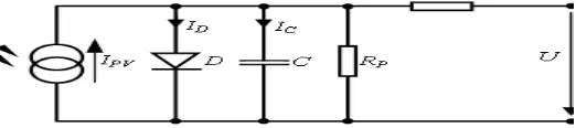
A PV generator consists of an assembly of solar cells, connections, protective parts, supports etc. Solar cells are made of semiconductor materials (usually silicon), which are specially treated to form an electric field, positive on one side (backside) and negative on the other (towards the sun). Then solar energy (photons) hits the solar cell, electrons are knocked loose from the atoms in the semiconductor material, creating electron-hole pairs. If electrical conductors are then attacked to the positive and negative sides, forming an electrical circuit, the electrons are captured in the form of electric current (photocurrent) [4].The model of the solar cell can be realized by an equivalent circuit that consists of a current source in parallel with a diode (Fig.1).
IJEDR1403002
International Journal of Engineering Development and Research (www.ijedr.org)2898
The p-n junction has a certain depletion layer capacitance, which is typically neglected for modelling solar cells. At increased inverse voltage the depletion layer becomes wider so that the capacitance is reduced similar to stretching the electrodes of a plate capacitor. Thus solar cells represent variable capacitance whose magnitude depends on the present voltage. This effect is considered by the capacitor C located in parallel to the diode Series resistance RS consists of the contact resistance of the cables as well as of the resistance of the semiconductor material itself. Parallel or shunt resistance RP includes the “leakage currents” at the photovoltaic cell edges at which the ideal shunt reaction of the p-n junction may be reduced. This is usually within the kΩ region and consequently has almost no effect on the current-voltage characteristic [1]. The diode is the one which determines the current voltage characteristic of the cell. The output of the current source is directly proportional to the light falling on the cell. The open circuit voltage increases logarithmically according to the Shockley equation which describes the interdependence of current and voltage in a solar cell [1].I =
(exp
(1)
(2)
Where
Is the photo current. Is the reverse saturation current of the diode. q Is the electron charge. V Is the voltage across the diode. K Is the Boltzmann's constant. T is the junction temperature. N is the ideality factor of the diode. And are the series and shunt resistors of the cell, respectively. = 0.0017 A/◦C is the cell's short circuit current temperature coefficient. Is the solar radiation (W/ ).
Figure 2 Matlab Simulink PV module.
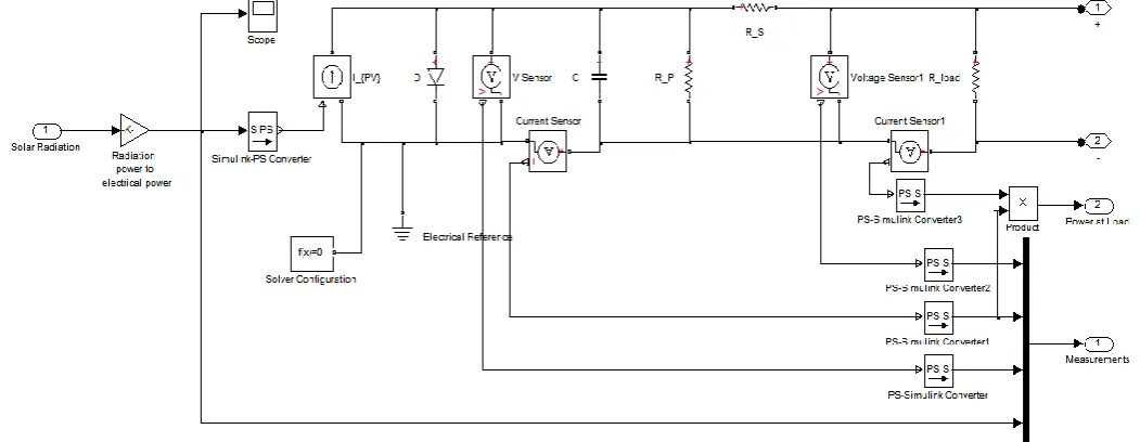
The solar system model consists of three Simulink blocks: the solar model block , the PV model block and energy conversion modules. The solar model block implements the mathematical model of the solar radiation. This is done by using standard Simulink and Matlab modules and functions. This block allows selecting different type of patterns for the solar radiation. The PV module implements the equivalent circuit of a solar cell, shown in Fig.1. Standard functions and blocks of Matlab and Simulink were used to obtain this model. Its structure is presented in Fig 3.The output of the PV module is processed by an energy conversion block implemented with a PWM IGBT inverter block from standard Simulink/Sim-Power Systems library [1].
Figure 3 Matlab Simulink implementation of the PV module
2.2 Modelling the Wind Energy System
IJEDR1403002
International Journal of Engineering Development and Research (www.ijedr.org)2899
- Friction is neglected;- Stationary wind flow;
- Constant, shear-free wind flow; - Rotation-free flow;
- Incompressible flow (q=1.22 kg/m3);
- Free wind flow around the wind energy converter
On the above condition the maximum physical achievable wind energy conversion can be derived using a theoretical model that is independent of the technical construction of a wind energy converter [1]. The flow air mass has certain energy. This energy is obtained from the air movement on the earth’s surface determined by the difference in speed and pressure. This is the main source of energy used by the wind turbines to obtain electric power [7]. Wind energy systems harness the kinetic energy of wind and convert it into electrical energy or use it to do other work, such as pump water, grind grains, etc. The kinetic energy of air of mass m moving at speed v can be expressed as
= . (3) During time period t, the mass (m) of air through a given area A at speed v is:
M=
(4) Where ρ is the density of air ( )
Based on the above two equations, the wind power is
P= (5) As per the betz low no wind turbine can convert more than 59.3% of the kinetic energy of the wind into mechanical energy The theoretical maximum power efficiency of any design of wind turbine is 0.59. This is called the “power coefficient”
=0.59 So the power is
P=
ρ
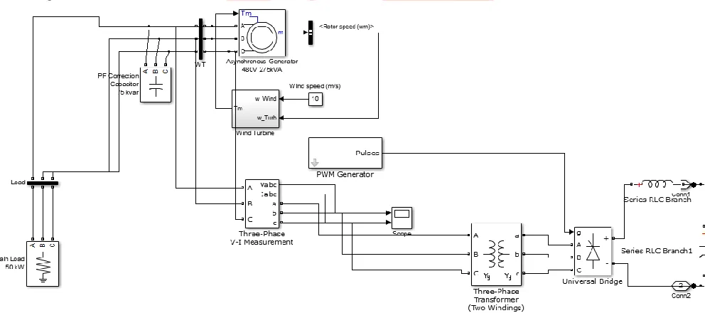
Cp is called the power coefficient of the rotor or the rotor efficiency. It is the fraction of the upstream wind power, which is captured by the rotor blades and has a theoretical maximum value of 0.59. In practical designs, maximum achievable Cp is between 0.4 and 0.5 for high-speed, twoblade turbines and between 0.2 and 0.4 for low-speed turbines with more blades. A Matlab Simulink model, based on the equations mentioned above, was developed for the wind generator module. This model is shown in Figure 4.
Figure 4 The Matlab Simulink model of the wind turbine Induction generator module.
III. 3.HYBRID SYSTEM DESIGN
3.1.Components of Hybrid
System:-(1) Photovoltaic: - Photovoltaic cells are made of semi-conducting materials and the most commonly used material is silicon. When sunlight is absorbed by these materials, the solar energy knocks electrons loose from their atoms, allowing the electrons to flow through the material to produce electricity.
(2) Wind turbine: - wind turbines use wind to generate electricity. When the wind blows, the combination of lift and drag forces on turbine blades causes the rotor to spin, and the turning shaft spins a generator to generate electricity.
(3) Inverter: - An inverter is a circuit for converting direct current (DC) to alternating Current (AC), which acts as the interface between the PV arrays and load
IJEDR1403002
International Journal of Engineering Development and Research (www.ijedr.org)2900
(5) Battery:- the function of batteries are to store the energy when generation is more than load demand, and supply the energy to the load when load demand is higher than generation.(6) Permanent magnet synchronous generator:-
They are commonly used to convert the mechanical power output of turbine into electrical power. In the rotating assembly of the PMSG the rotor contains the magnet, and the stator is the stationary armature that is electrically connected to a load.
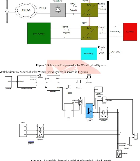
Figure 5 Schematic Diagram of solar Wind Hybrid System
The Matlab Simulink Model of solar Wind Hybrid System is shown in Figure 6
Figure 6 The Matlab Simulink Model of solar Wind Hybrid System 4. RESULTS
IJEDR1403002
International Journal of Engineering Development and Research (www.ijedr.org)2901
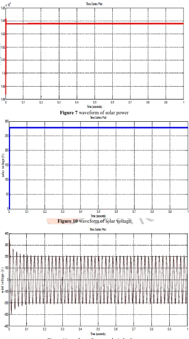
Figure 7 waveform of solar powerFigure 10 waveform of solar voltage
IJEDR1403002
International Journal of Engineering Development and Research (www.ijedr.org)2902
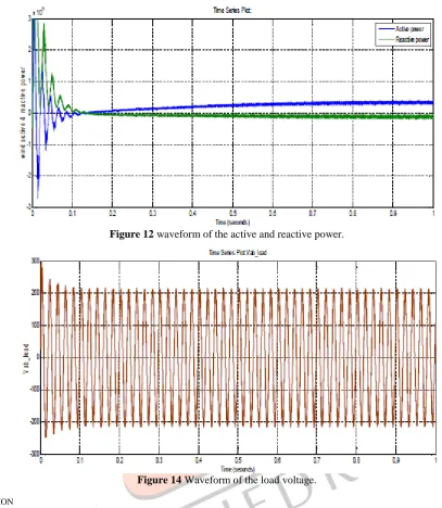
Figure 12 waveform of the active and reactive power.Figure 14 Waveform of the load voltage.
IV. CONCLUSION
In this project we describe a renewable energy hybrid generation system combining solar photovoltaic and variable speed wind turbine. In rural or remote sites the proposed renewable base stand-alone solar-wind hybrid system is most suitable solution. These solutions for this proposed system is available throughout the year.
REFERENCES
[1] Dorin Bica, Cristian Dragoç Dumitru, Adrian, “Isolated hybrid solar–wind-hydro renewable energy systems.” Scientific bulletin of the Petru Maior University of the Targu Mures Vol.7 (XXIV),No.2 2010 ISSN 1841-9267
[2] Basker Vairamohan,“ State of Charge Estimation Of Batteries.” A thesis presented for the Master of Science Degree, The University of Tennessee, Knoxville.
[3] M. N. Mansouri Ecole, M. Mansouri Ecole, M.F.Mimouni Ecole, “modeling and c o n t r o l energy management of a hybrid system associated a continuous load and coupled with the electrical network.” International journal of sciences and techniques of automatic control and computer engineering IJ-STA Vol. 2 No.2 pp 722-727 Dec. 2008.
[4] Shishir Kumar Pradhan, “Modeling and Simulation of PV array with boost converter: An open Loop Study” A thesis presented for the Bachelor of Technology Degree Department Of Electrical Engineering National Institute Of Technology Rourkela.
[5] Jinhong Jeon, “Development of A Grid Connected wind/PV/BESS Hybrid Distributed Generation System.” 19th International Conference on Electricity Distribution Vienna 21-24 May 2007 paper 0539
[6] Shalikram Dewangan, “stability enhancement of a wind energy embedded distribution system” A thesis presented for the Master of Engineering Degree Department Of Electrical Engineering SSCET Junwani Bhilai