Available online:
https://edupediapublications.org/journals/index.php/IJR/
P a g e | 2165Optimization of Wind Power Generator Frame by Using Cae
Software
1
K Pradeep Reddy,
2K Venkatesh,
3J Narsaiah
1
M.Tech student,
2Assistant professor,
3Assistant professor. Department of Mechanical
Engineering, Avn Institute of Engineering and Technology, Hyd, T.S
ABSTRACT
The generator considered in this project has a production capacity of 10KW and weight is 180Kgs. The weight of the generator is considered as static load. A static load of 180Kgs is applied on the generator frame from the centre point of the generator. Generally, generator has lot of movable parts. Due to these parts, generator has random vibrations. These vibrations can affect the generator. So, to check whether the generator frame is withstanding for these vibrations, generator is analyzed for dynamic analysis. Analysis was done by using Computer Aided Engineering (CAE) package.
This project involves 3d modelling and analysis of the generator frame. At first, 3d modelling of the generator frame was done using NX-CAD software. Next, the 3d model is imported to ANSYS software to perform analysis on the generator frame. From static analysis, deflections and stresses are documented for static load. Dynamic analysis is done on the generator frame to check the structure behaviour for random vibrations. Modifications are done to optimize the generator frame for above loads.
INTRODUCTION
Wind turbines, like aircraft propeller blades, turn in the moving air and power an electric generator that supplies an electric current. Simply stated, a wind turbine is the opposite of a fan. Instead of using electricity to make wind, like a fan, wind turbines use wind to make electricity. The wind turns the blades, which spin a shaft, which connects to a generator and makes electricity.
Turbine components include:
blade or rotor, which converts the energy in the wind to rotational shaft energy; a drive train, usually including a gearbox
and a generator;
a tower that supports the rotor and drive train; and
Other equipment, including controls, electrical cables, ground support equipment, and interconnection equipment.
Available online:
https://edupediapublications.org/journals/index.php/IJR/
P a g e | 2166The wind turbine generator converts
mechanical energy to electrical energy. Wind turbine generators are a bit unusual, compared to other generating units you ordinarily find attached to the electrical grid. One reason is that the generator has to work with a power source (the wind turbine rotor) which supplies very fluctuating mechanical power (torque).
METHODOLOGY
The methodology followed in the project is as follows:
3D model of the generator frame is done in NX-CAD
This 3d model is converted into parasolid and imported into ANSYS to perform finite element analysis.
Structural static analysis is performed with a generator weight as static load, and stresses and deflections are documented.
Modal analysis of the generator frame is carried out to calculate natural frequencies and their mode shapes and evaluate the dynamic characteristics.
Spectrum analysis is performed to check the frame behavior due to random vibrations as per the input PSD curve. One sigma deflections and stresses are plotted.
Design changes are made to strengthen the generator frame structure for operating conditions.
Structural static analysis is performed with a generator weight as static load, and stresses and deflections are documented on the modified generator frame.
Modal analysis is carried out to calculate natural frequencies and their mode shapes and evaluate the dynamic characteristics of the modified generator frame.
Spectrum analysis is performed to check the modified generator frame behavior due to random vibrations as per the input PSD curve. One sigma deflections and stresses are plotted.
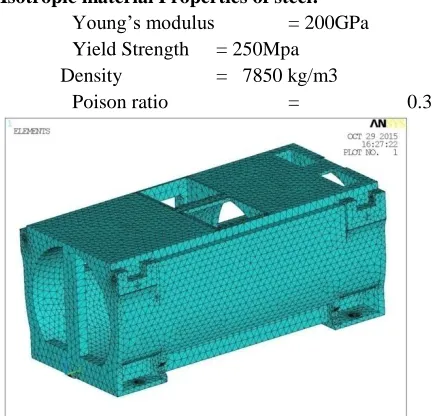
3D MODELLING OF GENERATOR FRAME
Fig shows 3d view of generator frame
FINITE ELEMENT ANALYSIS OF GENERATOR FRAME Material properties of generator frame:
The generator frame generally used in wind power mill is made of steel material.
Isotropic material Properties of steel: Young’s modulus = 200GPa Yield Strength = 250Mpa
Density = 7850 kg/m3
Poison ratio = 0.3
Fig. shows the Finite element model of the generator frame
Static analysis of generator frame: Boundary conditions:
The bolting positions of generator frame are constrained in all Dof.
Available online:
https://edupediapublications.org/journals/index.php/IJR/
P a g e | 2167weight of generator i.e180Kgs is distributed
inside of generator frame using mass 21 elements.
Fig. shows the Boundary conditions for static analysis on generator frame
Results: Deflections:
Fig shows Total Deflection for static analysis of generator frame
Von Mises Stress:
Fig. Von Mises stress for static analysis of generator frame
From the analysis, the maximum Von Misses stress of 14.03MPa is observed on the bolting
locations of the generator frame. The yield strength of the material used for generator frame is 250 MPa. The, maximum Von Misses stress observed from the analysis is 14.03MPa, which is less than the yield strength of the material. So, design of generator frame is safe for static loads.
Modal analysis of generator frame:
Modal analysis was carried out on generator frame to determine the first 10 natural frequencies and mode shapes of a structure.
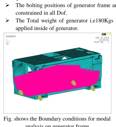
Boundary conditions:
The bolting positions of generator frame are constrained in all Dof.
The Total weight of generator i.e180Kgs is applied inside of generator.
Fig. shows the Boundary conditions for modal analysis on generator frame
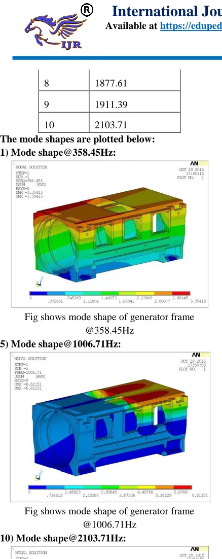
Table shows the first 10 natural Frequencies of generator frame.
MODE FREQUENCY
1 358.453
2 609.42
3 658.37
4 778.162
5 1006.71
6 1674.84
Available online:
https://edupediapublications.org/journals/index.php/IJR/
P a g e | 21688 1877.61
9 1911.39
10 2103.71
The mode shapes are plotted below: 1) Mode [email protected]:
Fig shows mode shape of generator frame @358.45Hz
5) Mode [email protected]:
Fig shows mode shape of generator frame @1006.71Hz
10) Mode [email protected]:
Fig shows mode shape of generator frame @2103.71Hz
From the modal analysis, the total weight of the generator frame + generator weight is observed for the analysis as 147.25 Kgs + 180 Kgs = 327.25 Kgs.
The maximum mass participation 229 Kgs is observed in X-dir for the frequency of 358.45Hz.
The maximum mass participation of 206 Kgs is observed in Y-dir for the frequency of 609.42Hz.
The maximum mass participation of 265 Kgs is
observed in Z-dir for the frequency of 658.37Hz. Spectrum analysis of generator frame:
Boundary conditions:
Fig. shows the Boundary conditions for power spectrum analysis of generator frame
The bolting positions of generator frame are constrained in all Dof.
The Total weight of generator i.e180Kgs is applied inside of generator.
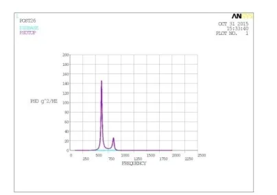
Fig shows input PSD curve for spectrum analysis of generator frame
Generator frame was subjected to Power spectrum analysis in X-direction, Y-direction and Z-direction as per above mentioned PSD values for
0 0.02 0.04 0.06
0 1000 2000 3000
P
S
D
g^2/HZ
Available online:
https://edupediapublications.org/journals/index.php/IJR/
P a g e | 2169specified frequencies. The results of power spectrum analysis of generator frame in X-dir, Y-dir, and Z-dir are shown below.
RESULTS:
1σ Deflections and stress in X-direction:
Fig shows total deflection of generator frame in X-dir
Fig shows von misses stress of generator frame in X-dir
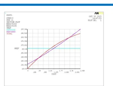
The von Mises stress in the structure on mounting frame for 1σ is 297 MPa as shown along the path (membrane + bending). The stresses are plotted along the path to identify whether the stresses are real or spurious stresses. From the above plots the maximum stress is 481 N/mm2, which is a spurious
stress and can be ignored.
Fig shows actual stress observed on generator frame due to spectrum analysis
The above figure shows membrane and bending stresses developed in generator frame for spectrum analysis in X-direction. The combination of bending and membrane stresses gives actual stresses developed in generator frame. The maximum von mises stress observed in generator frame for 1σ is 297.304MPa.
From the results the conclusions are made: 1σ deflection observed is : 0.079 mm
3σ deflection observed is :3 X 0.079 = 0.237 mm
This implies that only 0.3% of the time generator frame deflection reaches 0.237mm.
1σ stress observed is : 297 MPa
3σ stress observed is : 3 X 297 = 891 MPa
This implies that only 0.3% of the time generator frame stress reaches 891 MPa.
The PSD response on the top location of the generator frame for the given input PSD curve is shown in the below figures.
Figure shows PSD values at base and top locations of generator frame in linear scale
Available online:
https://edupediapublications.org/journals/index.php/IJR/
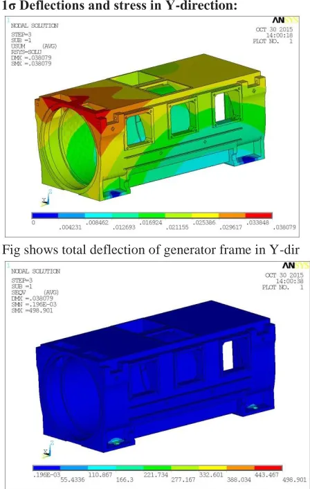
P a g e | 2170results and graphs, 3σ stress of generator frame is higher than the yield strength of the material. So, the generator frame is not safe design in X-direction and efforts are made to strengthen the generator frame. 1σ Deflections and stress in Y-direction:
Fig shows total deflection of generator frame in Y-dir
Fig shows von misses stress of generator frame in Y-dir
The von Mises stress in the structure on mounting frame for 1σ is 312.935 MPa as shown along the path (membrane + bending). The stresses are plotted along the path to identify whether the stresses are real or spurious stresses. From the above plots the maximum stress is 490.901 N/mm2, which
is a spurious stress and can be ignored.
Fig shows actual stress observed on generator frame due to spectrum analysis
The above figure shows membrane and bending stresses developed in generator frame for spectrum analysis in Y-direction. The combination of bending and membrane stresses gives actual stresses developed in generator frame. The maximum von mises stress observed in generator frame for 1σ is 312.935MPa.
From the results the conclusions are made: 1σ deflection observed is : 0.0380 mm
3σ deflection observed is :3 X 0.0380 = 0.114 mm
This implies that only 0.3% of the time generator frame deflection reaches 0.114 mm.
1σ stress observed is : 312 MPa
3σ stress observed is : 3 X 312 = 936 MPa
This implies that only 0.3% of the time generator frame stress reaches 936 MPa.
The PSD response on the top location of the generator frame for the given input PSD curve is shown in the below figures. Both linear and log scales are shown below.
Figure shows PSD values at base and top locations of generator frame in linear scale
Available online:
https://edupediapublications.org/journals/index.php/IJR/
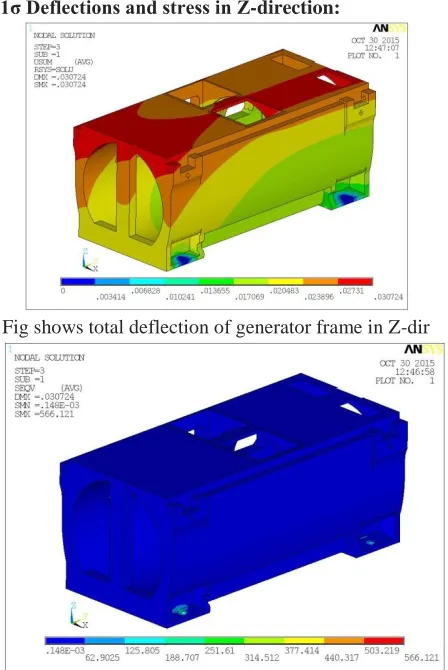
P a g e | 2171results and graphs, 3σ stress of generator frame is higher than the yield strength of the material. So, the generator frame is not safe design in Y-direction and efforts are made to strengthen the generator frame. 1σ Deflections and stress in Z-direction:
Fig shows total deflection of generator frame in Z-dir
Fig shows von misses stress of generator frame in Z-dir
The von Mises stress in the structure on mounting frame for 1σ is 337.54 MPa as shown along the path (membrane + bending). The stresses are plotted along the path to identify whether the stresses are real or spurious stresses. From the above plots the maximum stress is 566.721 N/mm2, which is a
spurious stress and can be ignored.
Fig shows actual stress observed on generator frame due to spectrum analysis
The above figure shows membrane and bending stresses developed in generator frame for spectrum analysis in Z-direction. The combination of bending and membrane stresses gives actual stresses developed in generator frame. The maximum von mises stress observed in generator frame for 1σ is 337.542MPa.
From the results the conclusions are made: 1σ deflection observed is : 0.0307 mm
3σ deflection observed is :3 X 0.0307 = 0.0921 mm
This implies that only 0.3% of the time generator frame deflection reaches 0.237mm.
1σ stress observed is : 337.54 MPa
3σ stress observed is : 3 X 337 = 1011 MPa
This implies that only 0.3% of the time generator frame stress reaches 1011Mpa.
The PSD response on the top location of the generator frame for the given input PSD curve is shown in the below figures.
Figure shows PSD values at base and top locations of generator frame in linear scale
Available online:
https://edupediapublications.org/journals/index.php/IJR/
P a g e | 2172higher than the yield strength of the material. So, the generator frame is not safe design in Z-direction and efforts are made to strengthen the generator frame.
Therefore, generator frame has higher von mises stress than yield strength of material in X-dir, Y-dir and Z-dir. So, effects are made to strengthen the generator frame structure.
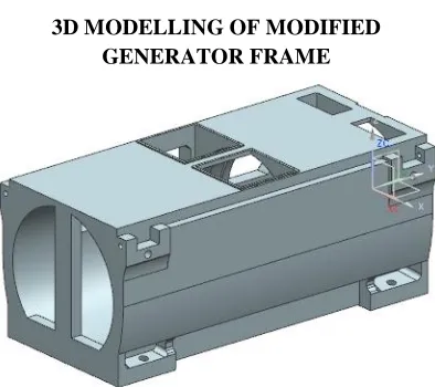
3D MODELLING OF MODIFIED GENERATOR FRAME
Fig shows 3d modelling of modified generator frame
FINITE ELEMENT ANALYSIS OF MODIFIED GENERATOR FRAME
Static analysis of modified generator frame: Results:
Deflections:
Fig shows Total Deflection for static analysis of modified generator frame
Von Mises Stress:
Fig shows Von Mises stress for static analysis of generator frame
From the analysis, the maximum Von Misses stress of 3.26MPa is observed on the bolting locations of the modified generator frame. The yield strength of the material used for modified generator frame is 250 MPa which is greater than the yield strength of the material is 250 MPa. So, design of generator frame is safe for static loads.
Modal analysis of modified generator frame:
Modal analysis was carried out to determine the first 10 natural frequencies and mode shapes of a structure.
Table shows the first 10 natural Frequencies
MODE FREQUENCY
1 617.717
2 853.741
3 1044.64
4 1097.9
5 1222.33
6 1847.37
7 1888.94
8 2113.63
9 2274.75
10 2420.11
Available online:
https://edupediapublications.org/journals/index.php/IJR/
P a g e | 21731) Mode [email protected]:
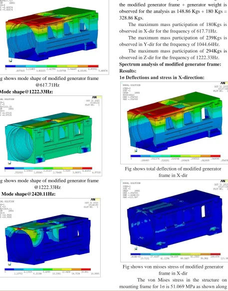
Fig shows mode shape of modified generator frame @617.71Hz
5) Mode [email protected]:
Fig shows mode shape of modified generator frame @1222.33Hz
10) Mode [email protected]:
Fig shows mode shape of modified generator frame @2420.11Hz
From the above modal analysis, the total weight of the modified generator frame + generator weight is observed for the analysis as 148.86 Kgs + 180 Kgs = 328.86 Kgs.
The maximum mass participation of 180Kgs is observed in X-dir for the frequency of 617.71Hz.
The maximum mass participation of 239Kgs is observed in Y-dir for the frequency of 1044.64Hz.
The maximum mass participation of 294Kgs is
observed in Z-dir for the frequency of 1222.33Hz. Spectrum analysis of modified generator frame: Results:
1σ Deflections and stress in X-direction:
Fig shows total deflection of modified generator frame in X-dir
Fig shows von misses stress of modified generator frame in X-dir
Available online:
https://edupediapublications.org/journals/index.php/IJR/
P a g e | 2174the path (membrane + bending). The stresses are plotted along the path to identify whether the stresses are real or spurious stresses. From the above plots the maximum stress is 123.387 N/mm2, which is a
spurious stress and can be ignored.
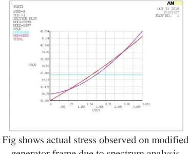
Fig shows actual stress observed on modified generator frame due to spectrum analysis
The above figure shows membrane and bending stresses developed in modified generator frame for spectrum analysis in X-direction. The combination of bending and membrane stresses gives actual stresses developed in modified generator frame. The maximum von mises stress observed in modified generator frame for 1σ is 51.06MPa. From the results the conclusions are made:
1σ deflection observed is : 0.054 mm
3σ deflection observed is :3 X 0.054 = 0.162mm
This implies that only 0.3% of the time generator frame deflection reaches 0.162mm.
1σ stress observed is : 51.06 MPa
3σ stress observed is : 3 X 51 = 153 MPa
This implies that only 0.3% of the time generator frame stress reaches 153 MPa.
The PSD response on the top location of the generator frame for the given input PSD curve is shown in the below figures. Both linear and log scales are shown below.
Figure shows PSD values at base and top locations of modified generator frame in linear scale
From above graphs, the generator frame has low dynamic response for frequencies. From above results and graphs, 3σ stress of generator frame is lower than the yield strength of the material. So, the modified generator frame is safe in design in X-direction.
1σ Deflections and stress in Y-direction:
Fig shows total deflection of modified generator frame in Y-dir
Available online:
https://edupediapublications.org/journals/index.php/IJR/
P a g e | 2175The von Mises stress in the structure on mounting frame for 1σ is 42.034 MPa as shown along the path (membrane + bending). The stresses are plotted along the path to identify whether the stresses are real or spurious stresses. From the above plots the maximum stress is 122.066 N/mm2, which is a
spurious stress and can be ignored
Fig shows actual stress observed on modified generator frame due to spectrum analysis
The above figure shows membrane and bending stresses developed in modified generator frame for spectrum analysis in Y-direction. The combination of bending and membrane stresses gives actual stresses developed in modified generator frame. The maximum von mises stress observed in modified generator frame for 1σ is 42.034MPa. From the above results the following conclusions are made:
1σ deflection observed is : 0.0201 mm
3σ deflection observed is :3 X 0.0201 = 0.0603 mm
This implies that only 0.3% of the time generator frame deflection reaches 0.060 mm.
1σ stress observed is : 42.034 MPa
3σ stress observed is : 3 X 42 = 126 MPa
This implies that only 0.3% of the time generator frame stress reaches 126 Mpa.
The PSD response on the top location of the generator frame for the given input PSD curve is shown in the below figures. Both linear and log scales are shown below.
Figure shows PSD values at base and top locations of modified generator frame in linear scale
From above graphs, the modified generator frame has low dynamic response for frequencies. From above results and graphs, 3σ stress of modified generator frame is lower than the yield strength of the material. So, the modified generator frame is safe in design in Y-direction.
1σ Deflections and stress in Z-direction:
Fig shows total deflection of modified generator frame in Z-dir
Available online:
https://edupediapublications.org/journals/index.php/IJR/
P a g e | 2176The von Mises stress in the structure on mounting frame for 1σ is 71.42 MPa as shown along the path (membrane + bending). The stresses are plotted along the path to identify whether the stresses are real or spurious stresses. From the above plots the maximum stress is 181.608 N/mm2, which is a
spurious stress and can be ignored.
Fig shows actual stress observed on modified generator frame due to spectrum analysis
The above figure shows membrane and bending stresses developed in modified generator frame for spectrum analysis in Z-direction. The combination of bending and membrane stresses gives actual stresses developed in modified generator frame. The maximum von mises stress observed in modified generator frame for 1σ is 71.42MPa. From the above results the following conclusions are made:
1σ deflection observed is : 0.0227 mm
3σ deflection observed is :3 X 0.0227 = 0.0681 mm
This implies that only 0.3% of the time generator frame deflection reaches 0.0681mm.
1σ stress observed is : 71.42 MPa
3σ stress observed is : 3 X 71 = 213 MPa
This implies that only 0.3% of the time generator frame stress reaches 213 MPa.
The PSD response on the top location of the generator frame for the given input PSD curve is shown in the below figures. Both linear and log scales are shown below.
Figure shows PSD values at base and top locations of modified generator frame in linear scale
From above graphs, the modified generator frame has low dynamic response for frequencies. From above results and graphs, 3σ stress of modified generator frame is low than the yield strength of the material. So, the modified generator frame is safe in design in Z-direction.
Therefore, modified generator frame has von mises stress less than yield strength of material in X-dir, Y-dir and Z-dir. So, the modified generator frame structure is safe design.
RESULTS AND CONCLUSION
Generator frame and modified generator frame were modelled in NX-CAD software. Both Generator frame and modified generator were analysed for structural analysis.
Results of generator frame: Static analysis:
The maximum Von Misses stress of 14.03MPa is observed on the generator frame. The maximum stress is observed on the bolting locations of the generator frame. The yield strength of the material used for generator frame is 250 MPa. Modal analysis:
The results of the generator frame, following observations are made:
The total weight of the generator frame + generator weight is observed for the analysis as 147.25 Kgs + 180 Kgs = 327.25 Kgs.
Available online:
https://edupediapublications.org/journals/index.php/IJR/
P a g e | 2177 The maximum mass participation of 206 Kgs is observed in Y-dir for the frequency of 609.42Hz.
The maximum mass participation of 265 Kgs is observed in Z-dir for the frequency of 658.37Hz.
Spectrum analysis: Case-1: In x-axis
The combination of bending and membrane stresses gives actual stresses developed in generator frame. The maximum von mises stress observed in generator frame for 1σ is 297.304MPa.
From the above results the following conclusions are made:
1σ deflection observed is : 0.079 mm
3σ deflection observed is :3 X 0.079 = 0.237 mm
This implies that only 0.3% of the time generator frame deflection reaches 0.237mm.
1σ stress observed is : 297 MPa
3σ stress observed is : 3 X 297 = 891 MPa
This implies that only 0.3% of the time generator frame stress reaches 891 MPa.
Case-2: In y-axis
The combination of bending and membrane stresses gives actual stresses developed in generator frame. The maximum von mises stress observed in generator frame for 1σ is 312.935MPa.
From the above results the following conclusions are made:
1σ deflection observed is : 0.0380 mm
3σ deflection observed is :3 X 0.0380 = 0.114 mm
This implies that only 0.3% of the time generator frame deflection reaches 0.114 mm.
1σ stress observed is : 312 MPa
3σ stress observed is : 3 X 312 = 936 MPa
This implies that only 0.3% of the time generator frame stress reaches 936 MPa.
Case-3: In z-axis
The combination of bending and membrane stresses gives actual stresses developed in generator frame. The maximum von mises stress observed in generator frame for 1σ is 337.542MPa.
From the above results the following conclusions are made:
1σ deflection observed is : 0.0307 mm
3σ deflection observed is :3 X 0.0307 = 0.0921 mm
This implies that only 0.3% of the time generator frame deflection reaches 0.237mm.
1σ stress observed is : 337.54 MPa
3σ stress observed is : 3 X 337 = 1011 MPa
This implies that only 0.3% of the time generator frame stress reaches 1011Mpa.
Results of modified generator frame: Static analysis:
The maximum Von Misses stress of 3.26MPa is observed on the modified generator frame. The maximum stress is observed on the bolting locations of the modified generator frame. The yield strength of the material used for modified generator frame is 250 MPa.
Modal analysis:
The results of the modified generator frame, following observations are made:
The total weight of the modified generator frame + generator weight is observed for the analysis as 148.86 Kgs + 180 Kgs = 328.86 Kgs.
The maximum mass participation of 180Kgs is observed in X-dir for the frequency of 617.71Hz.
The maximum mass participation of 239Kgs is observed in Y-dir for the frequency of 1044.64Hz.
The maximum mass participation of 294Kgs is observed in Z-dir for the frequency of 1222.33Hz
Spectrum analysis: Case-1: In x-axis
The combination of bending and membrane stresses gives actual stresses developed in modified generator frame. The maximum von mises stress observed in modified generator frame for 1σ is 51.06MPa.
From the above results the following conclusions are made:
Available online:
https://edupediapublications.org/journals/index.php/IJR/
P a g e | 2178 3σ deflection observed is :3 X 0.054 = 0.162mm
This implies that only 0.3% of the time generator frame deflection reaches 0.162mm.
1σ stress observed is : 51.06 MPa
3σ stress observed is : 3 X 51 = 153 MPa
This implies that only 0.3% of the time generator frame stress reaches 153 MPa.
Case-2: In y-axis
The combination of bending and membrane stresses gives actual stresses developed in modified generator frame. The maximum von mises stress observed in modified generator frame for 1σ is 42.034MPa.
From the above results the following conclusions are made:
1σ deflection observed is : 0.0201 mm
3σ deflection observed is :3 X 0.0201 = 0.0603 mm
This implies that only 0.3% of the time generator frame deflection reaches 0.060 mm.
1σ stress observed is : 42.034 MPa
3σ stress observed is : 3 X 42 = 126 MPa
This implies that only 0.3% of the time generator frame stress reaches 126 MPa.
Case-3: In z-axis
The combination of bending and membrane stresses gives actual stresses developed in modified generator frame. The maximum von mises stress observed in modified generator frame for 1σ is 71.42MPa.
From the above results the following conclusions are made:
1σ deflection observed is : 0.0227 mm
3σ deflection observed is :3 X 0.0227 = 0.0681 mm
This implies that only 0.3% of the time generator frame deflection reaches 0.0681mm.
1σ stress observed is : 71.42 MPa
3σ stress observed is : 3 X 71 = 213 MPa
This implies that only 0.3% of the time generator frame stress reaches 213 Mpa.
Conclusion:
Firstly, Generator frame was modelled in NX-CAD software. The generator frame was imported to ANSYS software to perform structural analysis. In structural analysis, generator was analysed for static, modal and spectrum analysis. From the results, the maximum von misses stress of generator frame was less than the yield strength of the material but in case of spectrum analysis, the von misses stress of generator frame was more than the yield strength of material. So, modifications were done on the generator frame. The modified generator was analysed for 3 analyses. In all three cases, the von mises stress of the modified generator frame was less than the yield strength of the material. Hence, it was concluded that the modified generator frame was safe for structural loads.
REFERENCES
[1] Static and dynamics analysis of 2.0mw generator frame by Chaoyi Ding, Luping Dai and Hongche Guo
[2] Analysis of Structural Dynamics Turbo Generator Load on Foundation Structure for Estimation Stresses during Vertical Excavation Using Finite Element Method by Sanjay Gupta, [3] design and performance analysis of a 6 mw
medium-speed brushless dfig by E. Abdi, M.R Tatlow, R.A. McMahon, PJ. Tavner,
[4] Modelling of Turbine-generator and Foundation as Single Degree of Freedom Using Ruaumoko Programme by Shafii Abdullah, Nor Hayati Abdul Hamid,
[5] Design and Analysis of Generator and Converters For Outer Rotor Direct Drive Gearless Small-scale Wind Turbines by Yusuf Yasa, Erkan Mese
[6] Completion of a 1,120-MVA Turbine Generator for Huadian International Zouxian Power Plant in China by Seijiro Muramatsu, Kado Miyakawa, Mitsuru Onoda, Kazuhiko Takahashi, Kengo Iwashige