MAY, 2000
NEC America, Inc.
ND-70185 (E)ISSUE 3 STOCK # 200869
Fusion Network System Manual
NEC America, Inc. reserves the right to change the specifications, functions, or features, at any time, without notice.
NEC America, Inc. has prepared this document for use by its employees and customers. The information contained herein is the property of NEC America, Inc. and shall not be reproduced without prior written approval from NEC America, Inc.
NEAX and Dterm are registered trademarks of NEC Corporation.
All other brand or product names are or may be trademarks or registered trademarks of, and are used to identify products or services of, their respective owners.
MS-DOS and Microsoft are registered trademarks of Microsoft Corporation. Microsoft Windows 95 and Windows NT are trademarks of Microsoft Corporation.
Copyright 1998, 1999, 2000
NEC America, Inc.
ISSUE 1 ISSUE 2 ISSUE 3 ISSUE 4 DATE JANUARY, 1998 DATE MARCH, 1999 DATE MAY, 2000 DATE
ISSUE 5 ISSUE 6 ISSUE 7 ISSUE 8
DATE DATE DATE DATE
PAGE No.
1 2 3 4 5 6 7 8
i 1 2 3
ii 1 2 3
iii 1 2 3
iv 1 2 3
v 1 2 3
vi 1 2 3
vii 1 2 3
viii 1 2 3
ix 1 2 3
x 1 2 3
1 1 2 3
2 1 2 3
3 1 2 3
4 1 2 3
5 1 2 3
6 1 2 3
7 1 2 3
8 1 2 3
9 1 2 3
10 1 2 3
11 1 2 3
12 1 2 3
13 1 2 3
14 1 2 3
15 1 2 3
16 1 2 3
17 1 2 3
18 1 2 3
19 1 2 3
20 1 2 3
21 1 2 3
22 1 2 3
23 1 2 3
24 1 2 3
25 1 2 3
26 1 2 3
27 1 2 3
28 1 2 3
29 1 2 3
30 1 2 3
31 1 2 3
32 1 2 3
33 1 2 3
34 1 2 3
35 1 2 3
36 1 2 3
37 1 2 3
38 1 2 3
39 1 2 3
40 1 2 3
41 1 2 3
42 1 2 3
43 1 2 3
44 1 2 3
45 1 2 3
46 1 2 3
47 1 2 3
48 1 2 3
49 1 2 3
50 1 2 3
51 1 2 3
52 1 2 3
53 1 2 3
54 1 2 3
55 1 2 3
56 1 2 3
57 1 2 3
58 1 2 3
59 1 2 3
60 1 2 3
61 1 2 3
62 1 2 3
63 1 2 3
64 1 2 3
65 1 2 3
66 1 2 3
PAGE No.
ISSUE 1 ISSUE 2 ISSUE 3 ISSUE 4 DATE JANUARY, 1998 DATE MARCH, 1999 DATE MAY, 2000 DATE
ISSUE 5 ISSUE 6 ISSUE 7 ISSUE 8
DATE DATE DATE DATE
NEAX2400 IMX
67 1 2 3
68 1 2 3
69 1 2 3
70 1 2 3
71 1 2 3
72 1 2 3
73 1 2 3
74 1 2 3
75 1 2 3
76 1 2 3
77 1 2 3
78 1 2 3
79 1 2 3
80 1 2 3
81 1 2 3
82 1 2 3
83 1 2 3
84 1 2 3
85 1 2 3
86 1 2 3
87 1 2 3
88 1 2 3
89 1 2 3
90 1 2 3
91 1 2 3
92 1 2 3
93 1 2 3
94 1 2 3
95 1 2 3
96 1 2 3
97 1 2 3
98 1 2 3
99 1 2 3
100 1 2 3
101 1 2 3
102 1 2 3
103 1 2 3
104 1 2 3
105 1 2 3
106 1 2 3
107 1 2 3
108 1 2 3
109 1 2 3
110 1 2 3
111 1 2 3
112 1 2 3
113 1 2 3
114 1 2 3
115 1 2 3
116 1 2 3
117 1 2 3
118 1 2 3
119 1 2 3
120 1 2 3
121 1 2 3
122 1 2 3
123 1 2 3
124 1 2 3
125 1 2 3
126 1 2 3
127 1 2 3
128 1 2 3
129 1 2 3
130 1 2 3
131 1 2 3
132 1 2 3
133 1 2 3
134 1 2 3
135 1 2 3
136 1 2 3
137 1 2 3
138 1 2 3
139 1 2 3
140 1 2 3
141 1 2 3
ISSUE 1 ISSUE 2 ISSUE 3 ISSUE 4 DATE JANUARY, 1998 DATE MARCH, 1999 DATE MAY, 2000 DATE
ISSUE 5 ISSUE 6 ISSUE 7 ISSUE 8
DATE DATE DATE DATE
143 1 2 3
144 1 2 3
145 1 2 3
146 1 2 3
147 2 3
148 2 3
149 2 3
150 2 3
151 2 3
152 2 3
153 2 3
154 2 3
155 2 3
156 2 3
157 2 3
158 2 3
159 2 3
160 2 3
161 3
162 3
163 3
164 3
165 3
166 3
167 3
168 3
169 3
170 3
171 3
172 3
173 3
174 3
175 3
176 3
177 3
178 3
179 3
180 3
PAGE No.
1 2 3 4 5 6 7 8
181 3
182 3
183 3
184 3
185 3
186 3
187 3
188 3
189 3
190 3
191 3
192 3
193 3
194 3
195 3
196 3
197 3
198 3
PAGE No.
MAY, 2000
NEAX2400 IMX
Fusion Network System Manual
TABLE OF CONTENTS
Page
CHAPTER 1 INTRODUCTION . . . 1
1. General . . . 1
2. How to Follow This Manual . . . 1
3. Related Manuals . . . 2
CHAPTER 2 GENERAL . . . 3
1. What is Fusion and its Advantages. . . 3
1.1 Improved Inter-Office Service Features . . . 3
1.2 Use of Telephone Numbers . . . . 3
2. Free Numbering . . . 4
2.1 Centralized Maintenance Administration Terminal (MAT) . . . 4
3. Fusion System Configuration . . . 5
4. Node . . . . . . 6
5. Data Memory Configuration . . . 7
6. Fusion Network Examples . . . 8
7. Tandem Connections via Fusion Link . . . 10
CHAPTER 3 SYSTEM CONFIGURATION . . . . 11
1. Fusion System without FCH . . . 11
2. Fusion System with FCH . . . 12
2.1 System Configuration. . . 12
2.2 Redundancy of Fusion Link . . . . 12
3. System Considerations . . . 14
3.1 Fusion Network Conditions . . . 14
3.2 Centralized Billing - Fusion (Polling Method) . . . 18
3.3 Centralized Management Report-Fusion . . . 21
3.4 Fusion Attendant/Desk Console . . . 25
3.4.1 Operator Call. . . . 25
3.4.2 Central Office Incoming Call (Ring Down) . . . 26
3.4.3 Day/Night Change. . . 27
CHAPTER 4 INSTALLATION . . . 29
1. Anti-Static Caution . . . 29
1.1 Circuit Cards Required. . . 31
2. Key Setting on Circuit Cards . . . 32
2.1 PA-M96 (HUB) . . . 32
2.2 PA-FCHA (FCH) . . . 33
2.3 PA-24DTR (DTI) . . . 35
TABLE OF CONTENTS (CONTINUED)
Page
3. Mounting Circuit Cards in PIM . . . 40
3.1 Mounting HUB (PA-M96) in a PIM. . . 40
3.2 Mounting FCH (PA-FCHA) and DTI (PA-24DTR) Cards . . . 41
4. Connecting Cables. . . 42
4.1 Connecting DTI-FCH Front Cables . . . 42
4.2 Connecting 10 BASE-T Cables . . . 44
4.3 10 BASE-T Connection Procedure . . . 45
4.3.1 Procedure for 1-IMG System . . . 45
4.3.2 When using cable unit SR1201 ETIF CAU-n . . . 45
4.3.3 When not using the cable unit SR1201 ETIF CAU-n . . . 46
4.3.4 Procedure for 4-IMG System . . . 46
4.3.5 Procedure for IMX-U System . . . 47
CHAPTER 5 DATA PROGRAMMING . . . 57
1. Network Data Programming Summary . . . 58
1.1 Brand-new Fusion Network . . . 58
1.1.1 System Data. . . 58
1.1.2 Numbering Plan Data. . . 58
1.1.3 Station Numbering . . . 58
1.1.4 Fusion Link Data . . . 58
1.2 Upgrading a CCIS Network . . . 59
1.2.1 System Data. . . 59
1.2.2 Numbering Plan Data. . . 59
1.2.3 Station Numbering . . . 59
1.2.4 Fusion Link Data . . . 59
1.3 Fusion Link Data . . . 60
2. Assignment of System Data. . . 62
3. Assignment of FPC and MG and UNIT into Network . . . 65
3.1 AFMU . . . 65
4. Assignment of Logical RT in Network DM (NDM) . . . 66
4.1 ALRTN/ARTKN . . . 66
5. Assignment of Numbering Data for Telephone Numbers . . . 67
6. Assignment of Telephone Numbers . . . 70
6.1 Assignment of Connection Route/Trunk Data . . . 72
6.1.1 When FCH is mounted in a Extended Density Slot . . . 76
6.1.2 When FCH is Mounted in a High Density Slot . . . 78
7. Assignment of FCH Related Data . . . 81
7.1 Assignment of Access Code for Tandem Connection via FCCS - ACIS . . . 87
7.1.1 OGC . . . 87
7.1.2 OGCA. . . 89
7.1.3 LCR/LCRS . . . 90
7.2 Data Assignment for 52M-SDH Interface . . . 93
7.2.1 Data Programming . . . 94
7.3 FCCS Link via Internet/Intranet . . . 97
7.3.1 External Router . . . 97
7.3.2 FCCS Networking over IP . . . 104
Page
8. Office Data Sheets . . . 112
8.1 Data Sheet for AFMUPL . . . 112
8.2 Data Sheet for ALRTN . . . 113
8.3 Data Sheet for ANPD/ANPDL/ANDPN . . . 114
8.4 Data Sheet for ASPA/ASPAL . . . 115
8.5 Data Sheet for ALGNL . . . 116
8.6 Data Sheet for ALGSL (TYPE1) . . . 117
8.7 Data Sheet for ALGSL (TYPE2) . . . 118
8.8 Data Sheet for ASDT. . . 119
8.9 Data Sheet for ACRD . . . 120
8.10 Data Sheet for ACTK. . . 122
8.11 Data Sheet for AFCH . . . 123
8.12 Data Sheet for AFPC. . . 125
8.13 Data Sheet for ACAN . . . 127
8.14 Data Sheet for AFRT . . . 128
8.15 Data Sheet for AETH. . . 129
8.16 Data Sheet for AGIP . . . 130
8.17 Data Sheet for AFIP . . . 131
8.18 Data Sheet for AFRFL. . . 132
CHAPTER 6 POST INSTALLATION TEST . . . 133
1. How to Check Fusion Link by LEDs on FCH Card . . . 133
1.1 How to check LYR LED . . . 134
2. Repair Procedure When LED Indicates Abnormality . . . 134
2.1 Front Cable . . . 134
2.2 How to Perform the Fusion Link Test. . . 135
2.2.1 Fusion Link Test Mode Setting. . . 135
2.2.2 Loopback Point Designation . . . 135
2.3 Test Procedure . . . 137
3. FCCS Network Connection Test . . . 138
3.1 Station-to-Station Connection Test (via FCCS) . . . 138
3.1.1 FCCS Call Origination Test . . . 138
3.1.2 FCCS Call Termination Test . . . 139
3.2 ATTCON Connection Test (via FCCS) . . . 140
3.2.1 ATTCON Call Origination Test. . . 140
3.2.2 ATTCON Call Termination Test . . . 140
3.3 Line (LC, ELC, DLC Card) Connection Test (via FCCS). . . 141
3.3.1 Line Origination Test: Confirmation of Physical/Telephone STN Number . . . 141
3.3.2 Line Termination Test: Confirmation of Telephone STN Number . . . 141
3.3.3 Line Connection Test: Case of Hot Line/House Phone Involved . . . 141
3.4 3-party Conference Trunk Function Test (via FCCS). . . 142
3.5 FCCS Alternate Routing Test . . . 142
3.5.1 Primary Route Trunk Test . . . 143
3.5.2 Alternate Route Trunk Test . . . 143
4. Fusion and Non-Fusion Connection Tests . . . 143
4.1 When Seizing a Trunk from a Station . . . 144
4.2 When Seizing a Trunk from an ATTCON. . . 144
TABLE OF CONTENTS (CONTINUED)
Page
CHAPTER 7 TROUBLESHOOTING . . . 147
1. List of Fusion-related System Messages . . . 147
2. 3-B PM C-level Infinite Loop (Permanent) . . . 149
2.1 Repair Procedure . . . 149
3. 3-C PM C-level Infinite Loop (Temporary) . . . 151
3.1 Repair Procedure . . . 151
4. 3-D PM Lockup Failure (Permanent) . . . 151
4.1 Repair Procedure . . . 152
5. 3-E PM Lockup Failure (Temporary) . . . 152
5.1 Repair Procedure . . . 152
6. 13-H/I/J Signaling Link Failure (Permanent)/(Temporary)/(Recovery) . . . 153
6.1 Repair Procedure . . . 154
6.2 Repair Procedure . . . 155
7. 23-S FCH Failure Notification (Detection) . . . 155
7.1 Repair Procedure . . . 156
8. 23-T FCH Fault Notification (Recovery) . . . 159
9. 23-U FCH Status Information. . . 160
9.1 FLTINF = 00H Initial Setting Failure . . . 161
9.2 FLTINF = 18H Spanning Tree Abnormal Answer . . . 162
9.2.1 Repair Procedure . . . 163
9.3 FLTINF = 1DH ETHER Transfer Failure . . . 164
9.4 FLTINF = 1EH Spanning Tree Generation End . . . 165
9.5 FLTINF = 1FH Spanning Tree Generation Start . . . 166
9.6 FLTINF = 85H Checksum Verification Failure . . . 166
10. 23-W FCH Alternate Routing Start Notification . . . 167
11. 23-X FCH Alternate Routing End Notification . . . 167
CHAPTER 8 EX- FCCS . . . 169
1. General . . . 169
2. EX-FCCS Network Configuration. . . 170
2.1 Network Configuration. . . 170
2.2 Conditions for Network Establishment (NEAX2000 IVS2 to NEAX2400 IMX Connection) . . . 171
2.3 Conditions for Network Establishment (NEAX2400 IMX to NEAX2400 IMX Connection) . . . 172
2.4 Fusion Network Group (FUG) . . . 173
2.5 Interactions . . . 174
3. EX-FCCS Features . . . 175
3.1 Number Portability. . . 175
3.2 Centralized-MAT for EX-FCCS . . . 177
3.3 CCIS Features Activated with EX-FCCS. . . 180
3.4 Centralized Message Center Interface - EX-FCCS. . . 182
3.5 Centralized Billing - EX-FCCS (Polling Method) . . . 184
4. Data Programming . . . 185
4.1 Brand-new EX-FCCS Network . . . 186
4.1.1 To Log in to All Nodes in EX-FCCS Network . . . 186
4.1.2 To Access EX-FCCS Trunk via ACC + Telephone Number . . . 191
4.1.3 To Access EX-FCCS Trunk via EX-FCCS Telephone Number . . . 192
4.2 Upgrading CCIS Network to EX-FCCS Network. . . 193
4.2.1 Upgrading CCIS between FUGs to EX-FCCS Network . . . 193
Figure Title Page
Figure 2-1 Telephone Number . . . 3
Figure 2-2 Free Location . . . 4
Figure 2-3 Centralized MAT on Fusion Network . . . 4
Figure 2-4 Fusion System Configuration (with FCH). . . 5
Figure 2-5 Fusion System Configuration (without FCH) . . . 5
Figure 2-6 Maximum System Configuration . . . 6
Figure 2-7 Network Data Memory . . . 7
Figure 2-8 Network Data Memory Copy . . . 8
Figure 2-9 Closed Numbering Fusion-CCIS Network . . . 8
Figure 2-10 Open Numbering Fusion-CCIS Network . . . 9
Figure 2-11 Tandem Connections via Fusion Link . . . 10
Figure 3-1 Fusion System Configuration without FCH . . . 11
Figure 3-2 Fusion System Configuration with FCH . . . 12
Figure 3-3 Redundant Configuration (LANI, HUB, FCH, and DTI) . . . 13
Figure 3-4 Redundant Configuration (HUB, FCH, and DTI) . . . 13
Figure 3-5 Redundant Configuration (FCH and DTI). . . 13
Figure 3-6 Non-Redundant Configuration . . . 14
Figure 3-7 Fusion Network Topologies . . . 14
Figure 3-8 Leading Tandem Connections . . . 15
Figure 3-9 Maximum Number of Ports between Nodes . . . 15
Figure 3-10 Connection Trunk Alternate Routing . . . 16
Figure 3-11 Fusion Network on an Associated Basis . . . 16
Figure 3-12 Centralized Billing - Fusion (1/3) . . . 18
Figure 3-13 Centralized Management Report-Fusion . . . 21
Figure 3-14 Centralized Management Report-Fusion (Example 1). . . 22
Figure 3-15 Centralized Management Report-Fusion (Example 2). . . 23
Figure 3-16 Centralized Management Report-Fusion (Example 3). . . 24
Figure 3-17 Operator Calls on a Fusion Network . . . 25
Figure 3-18 Ring Down Calls on a Fusion Network. . . 26
Figure 3-19 Day/Night Information Transfer by ATTCON/DESKCON. . . 27
Figure 3-20 Day/Night Information Transfer . . . 27
Figure 4-1 Static Caution Indicator . . . 29
Figure 4-2 How to Use the Anti-static Kit. . . 30
Figure 4-3 Circuit Cards for Fusion . . . 31
Figure 4-4 Switch Setting on HUB (PA-M96) Card . . . 32
Figure 4-5 Switch Setting on FCH (PA-FCHA) Card . . . 33
Figure 4-6 Switch Locations on DTI (PA-24DTR) Card. . . 35
Figure 4-7 Mounting HUB Card in PIM 0. . . 40
Figure 4-8 Mounting FCH and DTI Cards . . . 41
Figure 4-9 Connecting Front Cables . . . 42
Figure 4-10 FCH Cascade Connections . . . 43
Figure 4-11 Overall 10 BASE-T Connections . . . 44
Figure 4-12 Connecting 10 BASE-T Cables (example). . . 48
Figure 4-13 Examples of Ethernet Cable Connection-FCH in PIM0 (1-IMG System) (1/2). . . 49
Figure 4-14 Examples of Ethernet Cable Connection-FCH in PIM1 (1-IMG System) . . . 51
Figure 4-15 Examples of Ethernet Cable Connection-FCH in PIM2 (1-IMG System) (1/2). . . 52
Figure 4-16 Examples of Ethernet Cable Connection-FCH in PIM3 (1-IMG System) (1/2). . . 54
LIST OF FIGURES (CONTINUED)
Figure Title Page
Figure 5-2 Fusion-CCIS Network . . . 60
Figure 5-3 How to Upgrade the Numbering Plan Data of an Existing CCIS Network . . . 61
Figure 5-4 Assignment of Memory Block. . . 62
Figure 5-5 LDM and NDM Allocation (ASYDL) . . . 62
Figure 5-6 Self-FPC Assignment. . . 63
Figure 5-7 ASYDN Command Display (example) . . . 64
Figure 5-8 Assignment of Module Accommodation Data . . . 65
Figure 5-9 AFMU Command Display. . . 65
Figure 5-10 Telephone Number Required. . . 66
Figure 5-11 Assignment of Logical Route Number . . . 66
Figure 5-12 ALRTN Command Display . . . 67
Figure 5-13 Telephone Number Allocation . . . 67
Figure 5-14 ANPDN Sample Data Sheet . . . 68
Figure 5-15 ANPDN Command Display . . . 68
Figure 5-16 ASPAN Sample Data Sheet. . . 69
Figure 5-17 ASPAN Command Display. . . 69
Figure 5-18 ALGSN Sample Data Sheet. . . 70
Figure 5-19 ALGSN Command Display (example) . . . 71
Figure 5-20 B-ch and D-ch . . . 72
Figure 5-21 ACRD Command Display (example) . . . 72
Figure 5-22 ACTK Command Display (example) . . . 76
Figure 5-23 Mounting FCH and DTI Cards in Regular Density Slots . . . 76
Figure 5-24 Mounting FCH and DTI Cards in High-Density Slots . . . 78
Figure 5-25 How to Assign C_LEN Data (Type 2). . . 79
Figure 5-26 MBCT Command Display. . . 81
Figure 5-27 Assignment of FCH Number . . . 82
Figure 5-28 AFCH Command Display (example) . . . 82
Figure 5-29 AFRT Sample Data Sheet . . . 83
Figure 5-30 AFRT Command Display . . . 83
Figure 5-31 Fusion Network (example) . . . 84
Figure 5-32 AFPC Command Display (example) . . . 84
Figure 5-33 AFPC Sample Data Sheet . . . 85
Figure 5-34 ACAN Sample Data Sheet . . . 86
Figure 5-35 ACAN Command Display (example) . . . 86
Figure 5-36 Example of OGC . . . 87
Figure 5-37 Example of OGCA . . . 89
Figure 5-38 Example of LCR/LCRS . . . 90
Figure 5-39 External Router - Overview . . . 97
Figure 5-40 Hardware Connections for External Router . . . 97
Figure 5-41 Connection Route Class Data Sample. . . 98
Figure 5-42 Sample Data Assignment (ACTK) . . . 99
Figure 5-43 Assignment of FCHN (Example) . . . 100
Figure 5-44 Sample Data Assignment (AFPC) . . . 101
Figure 5-45 Internal LAN Routing Data Assignment Image (Example) . . . 101
Figure 5-46 Sample Data Assignment (AETH) . . . 102
Figure 5-47 How to Assign Destination IP and Next IP . . . 102
Figure 5-48 Sample Data Assignment (ACAN) . . . 103
Figure 5-49 FCCS Networking over IP - Overview . . . 104
Figure Title Page
Figure 5-51 Sample Data Assignment (ACRD) . . . 105
Figure 5-52 Sample Data Assignment (ACTK) . . . 105
Figure 5-53 Assignment of FCHN (Example) . . . 106
Figure 5-54 Sample Data Assignment (AETH) . . . 107
Figure 5-55 How to Assign Destination IP and Next IP . . . 107
Figure 5-56 Sample Data Assignment (ACAN) . . . 108
Figure 5-57 Sample Data Assignment (AFRT) . . . 108
Figure 5-58 Sample Data Assignment (AGIP). . . 109
Figure 5-59 “Basic LENS Data” Assignment of Speech Channels (AFIP) . . . 110
Figure 6-1 Fusion Network . . . 133
Figure 6-2 LED Indications on Fusion Link Related Circuit Cards . . . 134
Figure 6-3 Fusion Link Test Mode. . . 135
Figure 6-4 Loopback Points of DTI Card . . . 136
Figure 6-5 How to Set the Fusion Link Test Mode . . . 137
Figure 6-6 Loopback Point Designation . . . 137
Figure 6-7 Fusion Link-Test Results . . . 138
Figure 6-8 Station-to-Station Connection Test (origination) via FCCS . . . 139
Figure 6-9 ATTCON Connection Test (origination) via FCCS. . . 140
Figure 6-10 Line Connection Test (origination) via FCCS. . . 141
Figure 6-11 3-party Conference Trunk Function Test via FCCS . . . 142
Figure 6-12 Fusion Alternate Routing Test . . . 143
Figure 6-13 CCIS-FCCS Outgoing Call Test. . . 144
Figure 6-14 Loopback Points of SDT Card . . . 145
Figure 6-15 Loopback Setting by P-SW key on PA-SDTA Card . . . 145
Figure 7-1 Related Hardware . . . 148
Figure 7-2 3-B PM C-level Infinite Loop (Permanent) . . . 149
Figure 7-3 How to Initialize the FCH (PA-FCHA) Card . . . 149
Figure 7-4 How to Replace the FCH (PA-FCHA) Card . . . 150
Figure 7-5 3-C PM C-level Infinite Loop (Temporary) . . . 151
Figure 7-6 3-D PM Lockup Failure (Permanent) . . . 151
Figure 7-7 3-E PM Lockup Failure (Temporary) . . . 152
Figure 7-8 Fusion Link (Signaling Link) Failure . . . 153
Figure 7-9 13-H/13-I/13-J Signaling Link Failure System Message . . . 153
Figure 7-10 FCH-DTI Connection . . . 154
Figure 7-11 23-S FCH Failure Notification . . . 155
Figure 7-12 10 BASE-T Cable Connection Check . . . 156
Figure 7-13 How to Check 10 BASE-T Cables . . . 157
Figure 7-14 How to Replace HUB (PA-M96) Card . . . 158
Figure 7-15 23-T FCCH Fault Recovery Notification. . . 159
Figure 7-16 23-U FCCH Status Information . . . 160
Figure 7-17 23-U FCCH Status Notification - Initial Setting Failure. . . 161
Figure 7-18 23-U FCCH Status Notification - Spanning Tree Abnormal Answer . . . 162
Figure 7-19 Spanning Tree Abnormal Answer . . . 163
Figure 7-20 23-U ETHER Transfer Failure . . . 164
Figure 7-21 23-U FCCH Status Notification - Spanning Tree Generation End . . . 165
Figure 7-22 23-U FCCH Status Notification - Spanning Tree Generation. . . 166
Figure 7-23 23-U FCCH Status Notification - Checksum Verification Failure . . . 166
Figure 7-24 23-W FCCH Alternate Routing Start Notification . . . 167
LIST OF FIGURES (CONTINUED)
Figure Title Page
Figure 8-1 Network Connection Type . . . 170
Figure 8-2 NEAX2000 IVS2 to NEAX2400 IMX Connection . . . 171
Figure 8-3 NEAX2400 IMX to NEAX2400 IMX Connection. . . 172
Figure 8-4 Allowable SPAN from the Center FUG . . . 173
Figure 8-5 Patterns of Number Portability . . . 176
Figure 8-6 Centralized Maintenance - EX-FCCS . . . 179
Figure 8-7 PC Assignment in EX-FCCS Network . . . 181
Figure 8-8 Port Allocation and Related Command for CCIS Trunk . . . 187
Table Title Page
Table 4-1 SENSE Switch Setting . . . 32
Table 4-2 MODE Switch Setting. . . 34
Table 4-3 DIP Switch (SW14) Setting . . . 34
Table 4-4 Switch Setting Patterns for the DTI Card . . . 35
Table 4-5 Digital Pad Setting . . . 39
Table 5-1 Route Class Data Assignment . . . 73
Table 5-2 Data Programming Sheet for Regular Density Slot . . . 77
Table 5-3 Data Programming Sheet for High Density Slot. . . 80
Table 7-1 List of Fusion-related System Messages . . . 147
Table 8-1 EX-FCCS Network Type Classification . . . 170
Table 8-2 Patterns of Number Portability . . . 176
Table 8-3 NEAX2000 IVS2 Fault Information . . . 178
1. General
This manual covers the installation of the Fusion system.
2. How to Follow This Manual
This manual consists of the following chapters.
• CHAPTER 1 (INTRODUCTION)
Explains how to use this manual.
• CHAPTER 2 (GENERAL)
Outlines the Fusion system configuration and lists available service features.
• CHAPTER 3 (SYSTEM CONFIGURATION)
Explains the hardware configuration of the Fusion system.
• CHAPTER 4 (INSTALLATION)
Consists of the following topics:
• Static Cautions
• Switch Settings (PA-M96, PA-FCHA, PA-24DTR)
• CHAPTER 5 (DATA PROGRAMMING)
Provides basic data assignment procedures using the following examples.
• Installing a new Fusion network
• Upgrading a CCIS network
• CHAPTER 6 (POST INSTALLATION TEST)
Explains how to perform installation tests, focusing on the Fusion link connection test.
• CHAPTER 7 (TROUBLESHOOTING)
Explains Fusion-related system messages and the repair procedures.
• CHAPTER 8 (EX-FCCS)
Consists of the following EX-FCCS topics:
• Network Configuration
• Feature Descriptions
Related Manuals
3. Related Manuals
To complete the installation of the Fusion system, the following manuals are required:
• NEAX2400 IMX Circuit Card Manual
• NEAX2400 IMX Installation Manual
• NEAX2400 IMX Office Data Specification
1. What is Fusion and its Advantages
The main advantages of the Fusion network are as follows:
1.1 Improved Inter-Office Service Features
The Fusion system can eliminate the constraints normally associated with network services that are offered using Common Channel Inter-Office Signaling (CCIS).
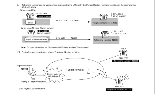
1.2 Use of Telephone Numbers
A Fusion system allows you to use Telephone Numbers in addition to the existing station numbers. (In the remainder of this manual, the existing station numbers are referred to as Physical Station Numbers.) Fusion service features are activated when a Telephone Number is dialed. The Telephone Number, which can be assigned on a station basis, is a unique number on a Fusion network. If required, numbering plan data, which is identical to that of an existing station number, can be used to maintain consistency of the number-ing plan. When this plan is adopted, you can use the same numbernumber-ing plan data after introducnumber-ing the Fusion system.
Note: A maximum of 16 digits can be used as a Telephone Number.
Figure 2-1 Telephone Number
Fusion features
are activated.
Telephone Number can be assigned to a station using the LENs or by the Physical Station Number depending on the programming as shown below.
Telephone Number: 410000 LENS
Physical Staion Number
STN: 2500 STN: 2000
Telephone Number: 410000
STN a
STN b
410001 Fusion Network
Fusion features are activated when a Telephone Number is dialed.
dialing a Telephone Number...
STN: Physical Station Number
LENS: 000010 410000
STN: 2000 410000
STN: 2000
STN: 2000
STN: 2000
STN: 2000
LENS: 000010
LENS: 000010
LENS: 000010 LENS: 000010
• When using LENs
• When using Physical Station Number
Telephone Number
Note: For more information, see "Assignment of Telephone Numbers" in this manual.
Telephone Number: 410000
Free Numbering
2. Free Numbering
A Telephone Number can be assigned to a desired station on the Fusion network using the simple command operation shown below.
Figure 2-2 Free Location
2.1 Centralized Maintenance Administration Terminal (MAT)
A Fusion network has one Network Control Node (NCN) and Local Nodes (LNs). The NCN has the Cen-tralized-MAT, which runs on Windows 95/NT. The MAT can collect fault information from all nodes on the network. The NCN has Network Data Memory, which stores the data related to network level. The Tele-phone Numbers, for example, can be changed using the Centralized-MAT at the NCN. The MAT also al-lows the user to manage network-level office data.
Telephone Number 411111 NCN LN Node A Node B STN 2000 STN 2000 STN 2000
STN: Physical Station Number
NCN: Network Control Node LN: Local Node
In this figure, the user is changing the location of Telephone Number "411111" to Node B.
user Telephone #: 411111
STN: 2000
Telephone #: 411111
STN: 2000 Node A
Node B Note
Note: The ALGSN command is used for assigning Telephone Numbers. See 5.6 "Assignment of Telephone Numbers" for more detail.
MAT Node C
LN
Fusion Network
Chang e loca
tion Node A Node B NCN LN Node A Node B Node C LN Node B
December 12 1997
AM 3:12:13
Node B FCH Failure
MG: 00
U : 02
G : 11
: : : FCH fault.... Fault Information Fault Information
Fault information can be collected at NCN via Fusion Link.
MAT PRT
Fusion Network Fusion Link
NCN: Network Control Node LN: Local Node 13-H
1. xxxx xxxx 0010 1222
4. x0010 1110 10110 1FFF
7. E23C CAAB12 000 0000 13-H
1. xxxx xxxx 0010 1222
4. x0010 1110 10110 1FFF
7. E23C CAAB12 000 0000
NEC
Note
3. Fusion System Configuration
The Fusion system can be divided into the following two types. Figure 2-4 shows a Fusion system with Fusion
Call Control Handler (FCH) cards.
Figure 2-4 Fusion System Configuration (with FCH)
Figure 2-5 shows a Fusion system without Fusion Call Control Handler (FCH) cards.
Figure 2-5 Fusion System Configuration (without FCH)
FCH
CPU
LANI
HUB
FCH
CPU
LANI
HUB
DTI DTI DTI
FCH
HUB DTI Fusion Link
1.5M
Dch: 64K-1.5M
CPU
LANI FCH
HUB DTI Fusion Link
1.5M
Dch: 64K-1.5M Node B
Node A Node C
10BASE-T 10BASE-T 10BASE-T
TI: Digital Trunk Interface FCH: Fusion Call Control Handler LANI: LAN Interface DTI
4.9 ft.
4.9 ft. 4.9 ft.
4.9 ft.
CPU LANI
CPU LANI DTI
DTI DTI DTI DTI
Fusion Link Fusion Link
CPU LANI
DTI Node B
Node A Node C
10BASE-T 10BASE-T
HUB
T1 Link T1 Link
Node
4. Node
A Fusion network consists of the following types of nodes:
• Network Control Node
Network Control Node, which must be assigned on a Fusion network, manages other nodes on the network. This node has the Centralized-MAT to collect fault information from other nodes on the network. Multiple nodes cannot be assigned as a Network Control Node.
• Local Node
All nodes other than Network Control Node are called Local Node. Fault information generated at a Local Node is sent to the Network Control Node via a Fusion Link, allowing the Network Control Node to collect
the fault information. A Fusion network can have a maximum of 16 nodes on the network. (See Figure 2-6.)
Note: The actual number of nodes varies with system configurations.
• Center Node (for Centralized Billing - Fusion)
This node collects the billing information from other nodes as well as the self-node. For this reason, the node is called Center Node for Centralized Billing - Fusion. Multiple Center Nodes can be assigned on the network by specifying the polling destinations, which can be set by the ASYDL command - SYS 1 Indexes 608 through 639. At the Center Node, the user can select “polling destinations” by setting 1 to the FPC of the corresponding nodes. For more information, see the NEAX2400 IMX Office Data Specification.
Figure 2-6 Maximum System Configuration
N1
N2
N3 N4
N5
N6 N7 N8 N9 N10 N11 N12 N13
N14 N15
N16
N: Node Fusion network
5. Data Memory Configuration
Each node on a Fusion network has the following three kinds of Data Memory:
• Data Memory (DM)
• Local Data Memory (LDM)
• Network Data Memory (NDM) - Programmable only by the NCN.
When the contents of the NDM are changed at NCN, the new data is automatically copied to the NDM of each
node. The NDM of the NCN functions as master memory. Figure 2-7 shows how a Telephone Number change
is performed in a Fusion network.
Figure 2-7 Network Data Memory
Telephone Number Change
410000 410001 (for self-Node)
420000 420001 (for Node B) 430000 430001 (for Node C) 440000 440001 (for Node D)
NCN
410000 410001
420000 420001
430000 430001
440000 440001
NDM (master)
NDM
NDM
NDM LN
LN LN
Node A
Node B
Node C
Node D
When Telephone Numbers are changed, the change at the NCN will affect all nodes on the network. In this figure, data change at Node
A is automatically transferred to each node.
Centralized MAT
Data Change...
copy copy
copy
updating NDM
at each node
Note
TCP/IP
Note: The data must be manually transferred using the CBCN command when the Fusion system is
Fusion Network Examples
When the NDM (master) is modified, the new data is automatically copied.
Figure 2-8 Network Data Memory Copy
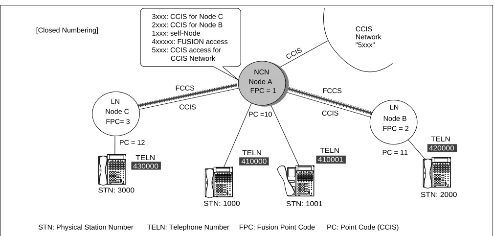
6. Fusion Network Examples
Figure 2-9 and Figure 2-10 show examples of Fusion networks. When incorporating the Fusion system with the existing CCIS network, all nodes must be connected via CCIS links.
Note: To connect a CCIS network and Fusion network, use STNs and TELNs respectively.
DM DM DM
LDM LDM LDM
NDM NDM
NDM (master)
Fusion Link
The standard size of each memory is as follows: DM (Data Memory): 4M Bytes
LDM (Local Data Memory): 2M Bytes NDM (Network Data Memory): 2M Bytes Change...
copy copy
NCN LN LN
NCN: Network Control Node LN: Local Node
430000 TELN 410000 TELN 410001 TELN 420000 TELN ... ... ... ... STN: 1000 STN: 3000 STN: 1001 STN: 2000 ... ... ... ... ... ... ... ... ... ... ... ... Node A NCN
FPC = 1
LN
Node B FPC = 2 LN Node C FPC= 3 CCIS Network "5xxx" FCCS FCCS CCIS CCIS [Closed Numbering]
3xxx: CCIS for Node C 2xxx: CCIS for Node B 1xxx: self-Node 4xxxxx: FUSION access 5xxx: CCIS access for CCIS Network
STN: Physical Station Number TELN: Telephone Number FPC: Fusion Point Code PC: Point Code (CCIS) PC = 12
PC =10
PC = 11
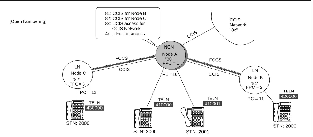
Figure 2-10 Open Numbering Fusion-CCIS Network
[conditions for Telephone Number Digits]
When incorporating the Fusion system with the CCIS network, consider the following conditions as to the available Telephone Number digits:
×: Available -: Not available
Note: When the network is Open Numbering, the “digits” in the table above must be the number of “Office Code digits + Telephone Number digits”.
Telephone Number Composition Display Inter-Office Service MCI SMDR
Dterm ATTCON/
DESKCON CCIS Fusion
4 digits or less Note × × × × × ×
4~8digits Note × - × - × ×
9 digits or more Note - - - ×
430000 TELN 410000 TELN 410001 TELN 420000 TELN ... ... ... ... STN: 2000 STN: 2000 STN: 2001 STN: 2000 ... ... ... ... ... ... ... ... ... ... ... ... Node A "80" NCN
FPC = 1
LN
Node B "81" FPC = 2 LN Node C "82" FPC= 3 CCIS Network "8x" FCCS FCCS CCIS CCIS CCIS
81: CCIS for Node B
82: CCIS for Node C
8x: CCIS access for CCIS Network
4x...: Fusion access [Open Numbering]
STN: Physical Station Number TELN: Telephone Number FPC: Fusion Point Code PC: Point Code (CCIS)
PC = 12
PC =10
Tandem Connections via Fusion Link
7. Tandem Connections via Fusion Link
Tandem connections via FCCS-ACIS can be established. In Figure 2-11, STN (A) can place a tandem call via
FCCS-ACIS.
Figure 2-11 Tandem Connections via Fusion Link 430000
TELN
410000
TELN
...
... ... ...
STN (B) STN (A)
... ... ... ...
LN
Node A
CO
FCCS Node B
NCN COT
Tandem connection FCCS ACIS is established.
FCCS
ACIS
Fusion systems can be divided into the following two types:
• Fusion system with FCH
• Fusion system without FCH
Note: Fusion Call Control Handler (FCH): PA-FCHA
This chapter explains the system configuration of each Fusion system.
1. Fusion System without FCH
A sample Fusion system configuration that does not use a DTI to carry D-channel is shown below. In this con-figuration, the Fusion link is established between nodes using Ethernet. The DTI card carries B-channels only
in this example. Figure 3-1 shows a Fusion System Configuration without FCH.
Figure 3-1 Fusion System Configuration without FCH
PCI Bus PCI Bus
Fusion Link
TSW/INT TSW/INT
MUX MUX
DTI DTI
LANI
CPU CPU
10 Base T 10 Base T
Max. 328 ft Max. 100m
Node A Node B
This figure shows a Fusion System Configuration without FCH.
TSW (Time Division Switch): PH-SW 10 MUX: PH-PC36
LANI (LAN Interface): PZ-PC19 DTI (Digital Trunk Interface): PA-24DTR
D-channel B-channel
HUB Max. 328 ft.
Max. 100m
Note
LANI
Note: A maximum of 4 HUBs can be cascaded per route.
Fusion System with FCH
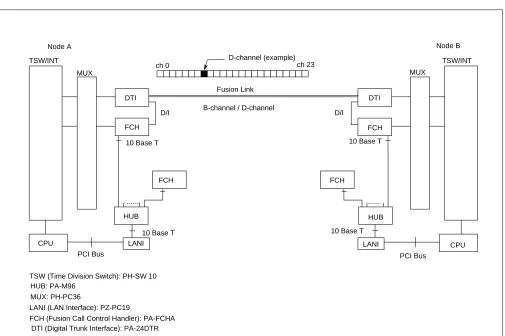
2. Fusion System with FCH
2.1 System Configuration
A sample Fusion system configuration that uses a DTI to carry D-channel is shown below. In this configu-ration, the Fusion link is established between nodes via the T1 link. Figure 3-2 shows a Fusion system con-figuration with FCH.
Figure 3-2 Fusion System Configuration with FCH
2.2 Redundancy of Fusion Link
The FCH (PA-FCHA) card handles a Fusion link, occupying one time slot of a frame by D/I function located on the DTI card. In terms of redundancy, the Fusion system (with FCH) can have one of the following config-urations.
• Redundant Configuration (LANI, HUB, FCH, and DTI)
• Redundant Configuration (HUB, FCH, and DTI)
• Redundant Configuration (FCH and DTI)
• Non-Redundant Configuration
PCI Bus PCI Bus
10 Base T
... ...
Fusion Link
D/I D/I
TSW/INT TSW/INT
MUX MUX
FCH
FCH FCH
FCH
DTI DTI
HUB HUB
LANI LANI
CPU CPU
10 Base T 10 Base T
Node A Node B
This figure shows a Fusion System Configuration with FCH.
TSW (Time Division Switch): PH-SW 10 HUB: PA-M96
MUX: PH-PC36
LANI (LAN Interface): PZ-PC19
FCH (Fusion Call Control Handler): PA-FCHA DTI (Digital Trunk Interface): PA-24DTR
B-channel / D-channel
ch 0 D-channel (example)ch 23
In Figure 3-3 LANI, HUB, FCH, and DTI are shown in a fully redundant configuration. This configuration is available for Release 3 or later software.
Figure 3-3 Redundant Configuration (LANI, HUB, FCH, and DTI)
In Figure 3-4 HUB, FCH, and DTI are shown in a redundant configuration.
Figure 3-4 Redundant Configuration (HUB, FCH, and DTI)
In Figure 3-5 FCH and DTI are shown in a redundant configuration.
Figure 3-5 Redundant Configuration (FCH and DTI)
FCH0
FCH1
DTI
DTI HUB1
....
.... HUB0 CPU#0
CPU#1
10 Base T
10 Base T
to the same route
Redundancy
n this case, LANI, HUB, FCH, and DTI are composed in a fully redundant configuration. Note that this configuration is available for
elease 3 or later software.
LANI#0-A LANI#0-B
LANI#1-A LANI#1-B
PCI Bus
FCH
FCH
DTI
DTI HUB
....
.... HUB LANI#0
CPU#0
PCI Bus
LANI#1 CPU#1
10 Base T
10 Base T
10 Base T 10 Base T
10 Base T
to the same route
Redundancy In this case, HUB , FCH, and DTI are composed in a redundant configuration.
PCI Bus
FCH
FCH
DTI
DTI ....
HUB LANI#0
CPU#0
PCI Bus
LANI#1 CPU#1
10 Base T
10 Base T
10 Base T
10 Base T to the same route
System Considerations
In Figure 3-6, no redundancy is shown in the Fusion link.
Figure 3-6 Non-Redundant Configuration
3. System Considerations
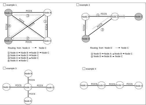
3.1 Fusion Network Conditions
This section explains how to design a Fusion network. In the following diagram, a Fusion Link is printed in a thick line while a CCIS link is printed in a dotted line.
Condition 1: The maximum number of nodes on a Fusion network is sixteen (16) nodes.
PCI Bus
FCH DTI
....
HUB LANI#0
CPU#0
PCI Bus
LANI#1 CPU#1
10 Base T
10 Base T
10 Base T In this case, no redundancy is taken as to Fusion link.
2 3 1
4
Node A Node B Node D Node C Node A Node D Node C
Node A Node B Node C Node A Node C
2
1Node D Node A Node B Node C Node D Node B Node C
2 3
4
Node A Node B
Node B
Node B
Node B
Node C Node D Node C Node D
Node A Node A
Node E
Node C
Node D Node D
Node C
FCCS
FCCS FCCS
FCCS
FCCS FCCS FCCS
FCCS FCCS
FCCS
FCCS FCCS
FCCS
FCCS
FCCS FCCS
1
2 1
example 1
example 3 example 4
example 2
Node A
Condition 2: A maximum of four (4) nodes can be connected as tandem nodes.
Figure 3-8 Fusion Tandem Connections
Condition 3: The available connection-route number ranges from 1 to 1023.
Condition 4: The available connection-trunk number of each route ranges from 1 to 4095.
Figure 3-9 Maximum Number of Ports between Nodes
FCCS FCCS FCCS
Tandem Connection over FCCS links
Node A Node B Node C Node D
max 4 nodes
A maximum of 4095 ports can be assigned on a
connection-route basis between nodes. DTI
card
DTI card
::
:: :::: :::: ::::
D ch
D ch
B ch DTI
card
DTI
card
DTI
card
DTI
card
DTI
card
DTI
card
DTI
card
D ch: Data Link B ch: Connection Trunk T1
T1
T1
T1
IMX IMX IMX
max 4095 ch
C_RT
System Considerations
Condition 5: Up to eight (8) routes can be assigned as alternate routes for a connection trunk.
Figure 3-10 Connection Trunk Alternate Routing
Condition 6: Connection trunks and the Fusion data link must be assigned on an “associated” basis.
Figure 3-11 Fusion Network on an Associated Basis
Condition 7: One fusion data link must be assigned on each T1 link.
Condition 8: A maximum of eight (8) data links can be used for a connection trunk for redundancy.
A maximum of eight (8) alternate routes can be assigned for Connection Trunks.
: : : : Node
Node
Node
Node
Node Alt-C_RT1
Alt-C_RT2
Alt-C_RT3
Alt-C_RT4
Alt-C_RT8
Node A Node B
Alt-C_RT: Alternate Connection Route
B ch
B ch D ch D ch
network on an "associated" basis network on a "quasi-associated" basis Node A
Node B
Node C
B ch
D ch
D ch
Node A
Node B
Node C
Condition 9: The maximum of data link speed is “1.5 Mbps.”
Condition 10: Connection Trunks (B ch) conform to the following specifications:
• Existing external trunk cannot be used as alternate routes for connection trunks.
• Billing information on connection trunks cannot be output.
• Under the following conditions, “connection trunk seizure NG” will occur:
Data Link Failure
Connection Trunk all busy
LANI (built-in) - FCH failure
• Connection test for connection trunks is not provided.
• Nailed Down connection is not provided for connection trunks.
Specifications on Release 2 or earlier software:
• PAD value for connection trunks is fixed to 0 db.
• Echo canceller (EC) / MPC control is not provided.
• Nailed Down connection is not provided for connection trunks.
Condition 11: If a “ layer 2 failure” occurs, the connections are released.
Condition 12: When fusion links and CCIS links coexist on a Fusion network, the following conditions should be considered:
A Fusion link may be used as a CCIS link through data programming. In this instance, if the other node accommodates a dedicated CCIS card, CCIS will not work even if the self-node accommodates a
Fusion-Link-Card. Therefore, the same Fusion-Link-Card must be accommodated at both nodes. Figure 3-13
System Considerations
3.2 Centralized Billing - Fusion (Polling Method)
This section explains the conditions of Centralized Billing - Fusion, focusing on when CCIS links are in-volved. To use this feature, select Center Node(s) on the Fusion network.
FCCS
FCCS
FCCS Fusion Network
- Node A (Fusion - Center Node) collects the billing information of Nodes B and C via FCCS using polling method. - Example 1
billing information
of Node C
billing information
of Node B
- Example 2
- Example 3
CCIS
IMX non IMX
CCIS
IMX non IMX
CCIS - Center Node
CCIS - Center Node
CCIS IMX IMX IMX CCIS IMX
CCIS - Center Node
CCIS - Center Node In either case, "Centralized Billing - CCIS" is used. (The size of call base table is 144 Bytes.)
In either case, "Centralized Billing - CCIS" is used. (The size of call base table is 144 Bytes.) IMX IMX IMX 0!KK01090010030020210 100100100202070010010 0000000004111106341997 1225223209199712252314 010112345000000000008 ...
Billing Format: CCIS
144 Bytes Call Base Table
0!KK01090010030020210 100100100202070010010 0000000004111106341997 1225223209199712252314 010112345000000000008 ...
Billing Format: CCIS
144 Bytes Call Base Table
0!KK01090010030020210 100100100202070010010 0000000004111106341997 1225223209199712252314 010112345000000000008 ...
Billing Format: CCIS
144 Bytes Call Base Table
0!KA01090010030020210 100100100202070010010 0000000004111106341997 1225223209199712252314 010112345000000000008 ...
Billing Format: CCIS
144 Bytes Call Base Table
Node A Node A Node A Node A Node C Node B Node B Node B Node B 12345566 451566465 876464646 646522130 0221313131 654654654 12345566 451566465 876464646 646522130 0221313131 654654654 polling
: Fusion Call Control
Signal (FCCS)
: Common Chanel
Inter-Office Signaling (CCIS)
SMDR equipment
polling
Fusion - Center Node
: Fusion Call Control Signal (FCCS)
Figure 3-12 Centralized Billing - Fusion (2/3)
FCCS
FCCS
Fusion Network - Example 4
- Example 5
CCIS IMX IMX IMX Node B Node C
Fusion - Center Node CCIS - Center Node
FCCS Fusion Network Fusion Network CCIS CCIS CCIS IMX non IMX non IMX IMX IMX IMX IMX
Fusion - Center Node
FCCS
FCCS
FCCS
Fusion - Center Node
DPC0: Node D DPC0: Node C DPC0: Node A
CCIS - Center Node
• Node A collects the billing information of Node B and Node C via FCCS using polling method.
• Node A sends the billing information of Node A, Node B, and Node C to Node D.
CCIS - Center Node
Node A Node B Node C Node A Node A Node B Node C Node D SMDR equipment SMDR equipment SMDR equipment SMDR equipment SMDR equipment ignores 12345566 451566465 876464646 646522130 0221313131 654654654 12345566 451566465 876464646 646522130 0221313131 654654654 Billing Information
of Node B
12345566 451566465 876464646 646522130 0221313131 654654654 Billing Information
of Node B
Billing Information
of Node C
polling 12345566 451566465 876464646 646522130 0221313131 654654654 12345566 451566465 876464646 646522130 0221313131 654654654 12345566 451566465 876464646 646522130 0221313131 654654654 12345566 451566465 876464646 646522130 0221313131 654654654 Billing Information
of Node B
12345566 451566465 876464646 646522130 0221313131 654654654 Billing Information
of Node C
polling
polling
polling
ignores polling
• Node A tries to collect the billing information of Node B, and Node C via FCCS using polling method.
(Node A cannot collect the billing information of Node C via FCCS.) • Node C sends the billing information via CCIS, ignoring polling from Node A.
• Node C deletes the self-Point Code (CCIS) when requiring to send billing information for polling from Node A.
• Node A tries to collect the billing information of Node B via FCCS using polling method.
(Node A cannot collect the billing information of Node B via FCCS.)
• Node B sends the billing information to Node C via CCIS, ignoring polling from Node A.
• Node B deletes the self-Point Code (CCIS) when requiring to send billing information for polling from Node A.
- Example 6
Billing Information
System Considerations
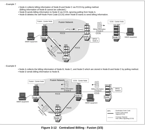
Figure 3-12 Centralized Billing - Fusion (3/3)
FCCS
FCCS
FCCS
Fusion Network - Example 7
- Example 8
CCIS IMX IMX non IMX IMX DPC0: Node D
CCIS - Center Node
SMDR equipment
SMDR equipment Fusion - Center Node
FCCS FCCS FCCS Fusion Network CCIS IMX IMX non IMX IMX DPC0: Node B CCIS - Center Node
SMDR equipment
SMDR equipment Fusion - Center Node
• Node A collects billing information of Node B and Node C via FCCS by polling method. (Billing information of Node B cannot be collected.)
• Node B sends billing information to Node D via CCIS, ignoring polling from Node A.
• Node B deletes the self-Node Point Code (CCIS) when Node B wants to send billing information.
• Node A collects the billing information of Node B, Node C, and Node D which are stored in Node B and Node C by polling method.
• Node D sends billing information to Node B.
Node A Node B
Node C
Node D
Node A Node B
Node C Node D 12345566 451566465 876464646 646522130 0221313131 654654654 12345566 451566465 876464646 646522130 0221313131 654654654 12345566 451566465 876464646 646522130 0221313131 654654654 Billing Information
of Node B
Billing Information
of Node B
Billing Information
of Node D
12345566 451566465 876464646 646522130 0221313131 654654654 Billing Information of Node C
12345566 451566465 876464646 646522130 0221313131 654654654 Billing Information of Node C
polling
polling
ignores
: Fusion Call Control
Signal (FCCS) : Common Chanel Inter-Office Signaling (CCIS) DPC : Destination Point Code : Destination Point Code
: Fusion Call Control Signal (FCCS)
3.3 Centralized Management Report-Fusion
To collect fault information in a Fusion network, the Centralized Management Report-Fusion is used. This feature provides automatic reporting of fault occurrence from Local Nodes to Center Node. Service condi-tions for this feature are shown below.
Figure 3-13 Centralized Management Report-Fusion
• Center Node for Centralized Management Report-Fusion is specified in the following system data:
ASYDL, SYS1, Index 532 (FPC of Center Node for Centralized Management Report-Fusion).
• At Center Node, system messages received from the other nodes are stored in the buffer memory for
Centralized Management Report-Fusion.
• The MAT connected to Center Node polls only the self-node.
• Office Name (ASYD, Index 96 through 115) is used for identification of each node.
• When a system message printer is connected to a node other than Center Node, system messages sent
to Center Node are also output to the system message printer.
• When a system message has been sent to Center Node, the message is regarded as an old message.
• When the system fails transmission of a system message to Center Node, retry operation is executed.
When the retry operation also fails, transmission is aborted and the message is to be sent together with the next system message.
FCCS
FCCS
FCCS
FCCS
Centralized MAT
Node A
Node B
Node C Node D
Fusion 13-H
1. xxxx xxxx 0010 1222
4. x0010 1110 10110 1FFF
7. E23C CAAB12 000 0000
NEC
System Considerations
The following explains service conditions for the network including both FCCS and CCIS links.
Example: 1 When the network comprises FCCS and CCIS links
Figure 3-14 Centralized Management Report-Fusion (Example 1)
Node A: To send system messages to Node C via Office B, assign Point Code of Node C (12) to ASYD, SYS 1, Indexes 184 and 185.
Node B: To send system messages to Node C, assign Fusion Point Code of Node C (3) to ASYDL, SYS1, Index 532. When this system data is assigned, system messages received from Node A are also transferred to Node C. However, when data is not assigned (0), system messages received from Node A are ig-nored and not transferred to Node C.
System messages received from Node A are not output to the system message printer connected to Node B.
Node C: Received system messages are stored in the memory area for Centralized Management Report-Fusion.
Node D: To send system messages to Node C, assign Fusion Point Code of Node C (3) to ASYDL, SYS1, Index 532.
Centralized MAT
Center Node: Node C
Fusion
NEC
13-H
1. xxxx xxxx 0010 1222
4. x0010 1110 10110 1FFF
7. E23C CAAB12 000 0000
NEC
PRT
PC=10 FPC=4
PC=11 FPC=2
PC=12 FPC=3
Node B Node C
Node A Node D
FCCS FCCS
Example: 2 When both FCCS and CCIS links are established between two nodes
Figure 3-15 Centralized Management Report-Fusion (Example 2)
Node A/B/C:Refer to Example 1 on the previous page.
Node D: When Point Code of Node C (12) is assigned to ASYD, SYS 1, Indexes 184 and 185, System
mes-sages are sent to Node C using CCIS. When this system data is not assigned (0) and Fusion Point Code of Node C (3) is assigned to ASYDL, SYS 1, Index 532, system messages are sent to Node C using FCCS.
Centralized MAT
Center Node: Node C
Fusion 13-H
1. xxxx xxxx 0010 1222
4. x0010 1110 10110 1FFF
7. E23C CAAB12 000 0000
NEC
PC=10 FPC=4
PC=11 FPC=2
PC=12 FPC=3
Node B Node C
Node A Node D
CCIS FCCS
FCCS
System Considerations
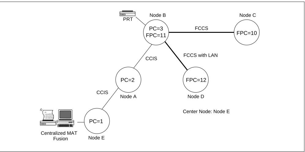
Example: 3 When a node is linked with LAN interface
Figure 3-16 Centralized Management Report-Fusion (Example 3)
Node A: To send system messages to Node E, assign Point Code of Node C (1) to ASYD, SYS 1, Indexes
184 and 185.
Node B: To send system messages to Node E, assign Point Code of Node C (1) to ASYD, SYS1, Indexes
184 and 185. When this system data is assigned, system messages received from Nodes C and D are also transferred to Node E. However, when this data is not assigned (0), system messages re-ceived from Nodes C and D are ignored and not transferred to Node E.
System messages received from Nodes C and D are not output to the system message printer con-nected to Node B.
Node C/D: To send system messages to Node E via Node B and Node A, assign Fusion Point Code of Node B (11) to ASYDL, SYS 1, Index 532.
Node E: Received system messages are stored in the memory area for Centralized Management
Report-Fu-sion.
Centralized MAT
Center Node: Node E
Fusion
NEC
13-H
1. xxxx xxxx 0010 1222
4. x0010 1110 10110 1FFF
7. E23C CAAB12 000 0000
NEC
PRT
PC=2 FPC=12
PC=3
FPC=11 FPC=10
Node B Node C
Node A
PC=1
Node E
Node D FCCS
FCCS with LAN CCIS
3.4 Fusion Attendant/Desk Console
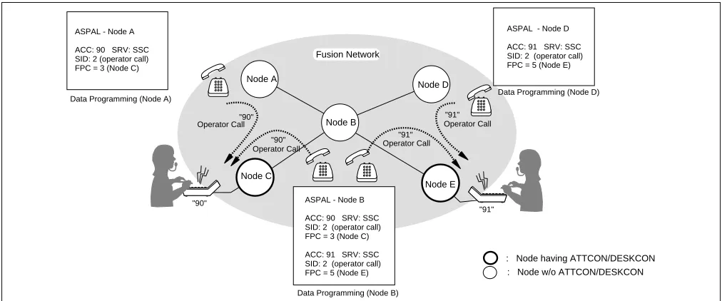
3.4.1 Operator Call
An operator call can be placed from each node by assigning the access code using the ASPAL/ASPAN command, which allows the user to specify an appropriate node on the Fusion network by entering the FPC. In this example, a station user at Node B can call up an operator at Node C or Node E by dialing “90” or “91.”
Note 1: As regards the following data (Waiting Call Display data), be sure to develop the unified data at each node: ASYD, SYS2, INDEX 8
ASYD, SYS2, INDEX 9
Note 2: When the connection routes (C_RT) are all busy, the operator call becomes in Night ATT mode.
Figure 3-17 Operator Calls on a Fusion Network
Node A
Node B
Node C
Node D
Node E "90"
"90"
"91"
"91"
"90"
"91"
: Node having ATTCON/DESKCON : Node w/o ATTCON/DESKCON ASPAL - Node A
ACC: 90 SRV: SSC
SID: 2 (operator call)
FPC = 3 (Node C)
Fusion Network
Data Programming (Node A) Data Programming (Node D)
Data Programming (Node B) Operator Call
Operator Call Operator Call
Operator Call
ASPAL - Node D
ACC: 91 SRV: SSC
SID: 2 (operator call)
FPC = 5 (Node E)
ASPAL - Node B
ACC: 90 SRV: SSC
SID: 2 (operator call)
FPC = 3 (Node C)
ACC: 91 SRV: SSC
SID: 2 (operator call)
System Considerations
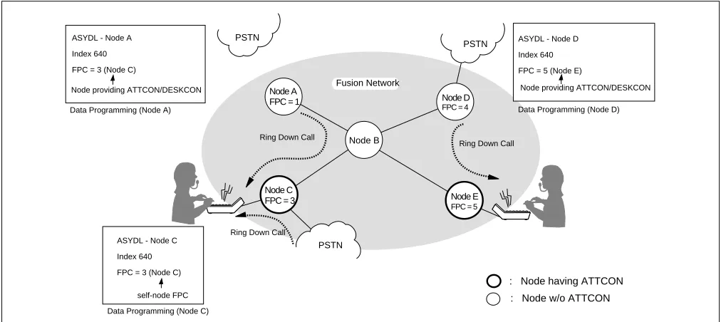
3.4.2 Central Office Incoming Call (Ring Down)
Each node can specify a terminating node for Ring Down calls using the system data. In this example, Node A and Node D specify Node C and Node E as the terminating node respectively. The terminating node is assigned using the ASYDL command (SYS 1, Index 640). Note that self-FPC is assigned at the terminating node.
Note 1: When assigning the data regarding the call termination to ATT, be sure to develop the unified data at each node.
Note 2: Terminating node cannot be assigned differently at each tenant (TN).
Note 3: When the connection routes (C_RT) are all busy, any attempted call via C.O. Line is not connected to the ATT. As a result, the calling party is provided with the Ring Back Tone (RBT), and even when a C_RT later becomes idle, the RBT connection is still maintained and the C.O. call does not terminate to the ATT.
Figure 3-18 Ring Down Calls on a Fusion Network
Node A
Node B
Node C
Node D
Node E
: Node having ATTCON
: Node w/o ATTCON
PSTN
PSTN PSTN
FPC = 1
FPC = 3 ASYDL - Node A
Index 640
FPC = 3 (Node C)
Node providing ATTCON/DESKCON
FPC = 4
FPC = 5 Fusion Network
Data Programming (Node A) Data Programming (Node D)
Data Programming (Node C)
Ring Down Call
Ring Down Call
Ring Down Call
ASYDL - Node C
Index 640
FPC = 3 (Node C)
self-node FPC
ASYDL - Node D
Index 640
FPC = 5 (Node E)
3.4.3 Day/Night Change
Day/Night information is transferred from an ATTCON/DESKCON to predetermined nodes. In this example, Node C specifies Node A and Node B as destination nodes by assigning FPCs 1 and 2 in Indexes 704-735. Node A and Node B specifies Node C as a terminating node for Ring Down calls from PSTN by assigning FPC 3 in Index 640. Node E specifies Node D as a destination.
Note 1: When assigning ATTCON/DESKCON on the Fusion network, be sure to develop the unified System Data
at each node.
Note 2: Terminating node cannot be assigned differently at each tenant (TN).
Figure 3-19 Day/Night Information Transfer by ATTCON/DESKCON
When an ATTCON/DESKCON is not provided on the Fusion network, Day/Night information is effective for node accommodating an external key box.
Day
Night Node A
Node C
Node D Fusion System with ATTCON/DESKCON
: Day mode
: Night mode
FPC = 1
FPC = 3
FPC = 4
Node B FPC = 2
Node E
FPC = 5
Data Programming (Node E) Data Programming (Node C)
by ATTCON/DESKCON
D/N information D/N information
ASYDL - Node E
Index 704 - 735
D/N information are
transferred: FPC: 4
ASYDL - Node C
Index 704 - 735
D/N information are
transferred: FPC: 1, 2
Day Night
Node A
Node B
Node C
Node D
Node E
ATTCON ATTCON
ATTCON ATT CO N
Key Box Key Box
External Key Box
Fusion System without ATTCON/DESKCON : Day mode
: Night mode
This chapter covers the installation of the Fusion system. The following topics are covered:
• How to set switches on the following circuit cards:
PA-M96 (HUB)
PA-FCHA (FCH)
PA-24DTR (DTI)
• How to mount the circuit cards
• How to run the 10 BASE-T cables
1. Anti-Static Caution
This manual provides Static Caution indicators on pages where work involving static-sensitive components is
described. When performing work accompanied by this mark, be sure to use the anti-static kit. Figure 4-1 shows
the Static Caution indicator.
Figure 4-1 Static Caution Indicator ATTENTION
Contents Static Sensitive Handling
Anti-Static Caution
Figure 4-2 shows the anti-static kit that is provided. Use the kit as shown below when handling static-sensitive components such as circuit cards and cables.
Figure 4-2 How to Use the Anti-static Kit
PBX
Connect the ground wire to the earth terminal of the frame.
Earth Terminal
Ground Wire
Conductive Sheet Wrist Strap
1.1 Circuit Cards Required
Depending on the system type, the following circuit cards are required to install the Fusion system:
• Fusion with FCH
HUB (PA-M96)
FCH (PA-FCHA)
DTI (PA-24DTR)
• Fusion without FCH
DTI (PA-24DTR)
HUB (PA-M96)
Before starting installation, make sure that all necessary cards are at your site.
Figure 4-3 Circuit Cards for Fusion
4 C 026A
1 2 3 4
OFF 1 2 3 4 5 6 7 8
OFF 1 2 3 4 5 6 7 8
OFF 1 2 3 4 5 6 7 8
OFF 1 2 3 4 5 6 7 8 OFF
1 2 3 4
OFF
1 2 3 4 5 6 7 8
OFF
1 2 3 4 5 6 7 8
OFF
1 2 3 4 5 6 7 8
OFF
1 2 3 4 5 6 7 8
OFF DTI (PA-24DTR)
HUB (PA-M96)
FCH (PA-FCHA)
DTI: Digital Trunk Interface FCH: Fusion Call Control Handler
4 C 0 26 A E 4 C 0 26 A E
1234 OFF
1234 OFF 12345678 OFF
12345678 OFF 12345678 OFF
1234567 OFF
1234 OFF
1234 OFF
12345678 OFF 12345678 OFF 12345678 OFF 12345678 OFF SW10 SW14 SW13 SW11 SW12 SW15 OPE N-OPE SW00 SW01 PCM FRM BER RMT AIS BL23 BL00 CN2
1 2 3 4 5 6
12345678
Key Setting on Circuit Cards
2. Key Setting on Circuit Cards
2.1 PA-M96 (HUB)
Set the SEL switch on the HUB (PA-M96) card(s), after referring to Figure 4-4 and Table 4-1.
Figure 4-4 Switch Setting on HUB (PA-M96) Card
Table 4-1 SENSE Switch Setting
SWITCH NAME SETTING STANDARD
SETTING DESCRIPTION
SENSE 0 Polarity indication on the STn lamps for TPn-Xports.
1 Not used.
2 × TPn-X ports operate as a repeater HUB. (Standard setting)
3 Data-Packet-Collision indication on the STn lamps for TPn-X ports.
4-F Not used.
Set the SENSE Switch arrow to the proper direction,
referring to Table 4-1.
SENSE Switch
HUB (PA-M96) Card HUB (PA-M96)
Card
4
C
02 6
A
E .
.
4 C 02 6AE
MB OPE
CR7
CR0 ST7
ST0
SENSE
TP7-X TP6-X TP5-X TP4-X TP3-X TP2-X TP1-X TP0-X
4 C
026
A
E
ATTENTION
Contents Static Sensitive Handling Precautions Required
~ ~
Note: 1 and 4 to F of the SENSE Switch are not available in this version.
4
C
02 6
A
2.2 PA-FCHA (FCH)
Set the switches on the FCH (PA-FCHA) card(s) as shown below. This card has DIP switches, whose key settings determine the time slots of the Fusion link. In Figure 4-5, CH3 is designated as the D/I channel in an example.
Figure 4-5 Switch Setting on FCH (PA-FCHA) Card 4 C 0 26 A E
1234
OFF 12345678
OFF 12345678
OFF 12345678
OFF 12345678
OFF
1234 OFF 12345678 OFF 12345678 OFF 12345678 OFF 12345678 OFF 4 C 0 26 A E SW14 SW13 SW12 SW11 SW10 OPE MB EST3 EST2 EST1 EST0 PWALM LYR LB LOAD MNT 10-BASE-T MODE DTI FCH ATTENTION Contents Static Sensitive Handling Precautions Required 4 C
02 6
A
E .
.
MODE Refer to Table 4-2. FCH (PA-FCHA) Card
FCH (PA-FCHA) Card
SW14 Refer to Table 4-3.
1 2 3 4
OFF
SW13
SW12
SW11
8 9 10 11 12 13 14 15
1 2 3 4 5 6 7 8
OFF
16 17 18 19 20 21 22 23
1 2 3 4 5 6 7 8
OFF
Note: Multiple choices are available.
1 2 3 4 5 6 7 8
0 1 2 3 4 5 6 7
OFF
D / I channel = CH3 (example)
SW10
1 2 3 4 5 6 7 8
OFF
Not Used
ON: T203 Timer = Variable
OFF: T203 Timer = 10 secs. (Standard Setting)
MNT
0 1 2 3
Key Setting on Circuit Cards
Note 1: 64Kbps is used for T1 or E1 interface.
56Kbps is used for T1 interface with bit stealing.
48Kbps is used for T1 interface with both bit stealing and Zero Code Suppression (or Bit 7 Stuffing).
Note 2: When n is bigger than 1, Time Slot Sequence Integrity (TSSI) must be guaranteed at the network side.
Note 3: The following is an example key setting when n = 2. SW11-1 = ON
SW11-2 = ON
Table 4-2 MODE Switch Setting
SWITCH NAME SETTING STANDARD
SETTING DESCRIPTION
MODE 0-7 Not used
8 × Standard setting
(When the DTI is connected with the card’s front cable)
9 Fusion link test mode
(When the DTI is connected with the card’s front cable)
A-F Not used
Table 4-3 DIP Switch (SW14) Setting
SWITCH NAME SWITCH
NUMBER SETTING
STANDARD
SETTING DESCRIPTION
SW14
1 ON × Positive logic for the D/I CONT OFF Negative logic for the D/I CONT
2 Note 1
ON × The fusion data link speed inserted onto the T1 interface Note 3 OFF 3 Note 1 ON × OFF
4 ON LAPD signal link performs as “network.” OFF LAPD signal link performs as “user.”
4
C
02 6
A
E
1 2 3 4
OFF
SW14-2 SW14-3 SPEED (Note 2)
ON ON 64Kbps × n (1~24)
ON OFF 48Kbps × n (1~24)
OFF ON 56Kbps × n (1~24)
OFF OFF Not used
2.3 PA-24DTR (DTI)
There are two types of the PA-24DTR (DTI) card as shown below. Refer to Figure 4-6 and Table 4-4 to set
each switch to the proper positions.
Figure 4-6 Switch Locations on DTI (PA-24DTR) Card
Table 4-4 Switch Setting Patterns for the DTI Card
SWITCH NAME SWITCH
NUMBER SETTING
STANDARD
SETTING MEANING
MB
UP Circuit card make busy
DOWN × Circuit card make busy cancel
SW13B
0 ON Internal Loopback: Set
OFF × Internal Loopback: Cancel
1 ON External Loopback: Set
OFF × External Loopback: Cancel
2 ON Payload Loopback: Set
OFF × Payload Loopback: Cancel
3 ON All Channel Make Busy: Set Note OFF × All Channel Make Busy: Cancel
Note: Dots printed in DIP switches represent the standard settings.
1 2 3 4
OFF
1 2 3 4
OFF 1 2 3 4 5 6 7 8
OFF
1 2 3 4 5 6 7 8
OFF 1 2 3 4 5 6 7 8
OFF
1 2 3 4 5 6 7
OFF
1234 OFF
1234 OFF 12345678 OFF
12345678 OFF 12345678 OFF
12345678 OFF SW4D SW5D SW6C SW39 SW58 SW25 OPE N-OPE MB SW13B PCM FRM BER RMT AIS BL23 BL00 CN2 ATTENTION Contents Static Sensitive Handling Precautions Required
DTI (PA-24DTR) Card
0 1