TOLERATION OF FAULT IN ENCODER AND
DECODER OF NANO MEMORY USING
EG-LDPC
J.Vishnu priya
1R.S.Prathap singh
21
M.Tech, PBR VITS, Kavali, Nellore (dt), AP
2
Associate Professor, PBR VITS, Kavali, Nellore(dt), AP (India)
ABSTRACT
Traditionally memory cells were the only circuitry susceptible to transient faults. The supporting
circuitries around the memory were assumed to be fault free. Due to the increase in soft error rate logic
circuits encoder and decoder circuitry around the memory block have become susceptible to soft errors as
well and must be protected .The key novel development is the fault free secure detector (FSD) error
correcting code (ECC) definition and associated circuitry that can detect errors in the received encoded
vector despite experiencing multiple transient faults in it circuitry .we prove that known classes of low
density parity check codes have the FSD property and further we quantify the importance of protecting
encoder and decoder circuitry.
Keywords
:
Decoder, Encoder, Fault Tolerant, Memory, Nano technology.
I.INTRODUCTION
Memory systems are protected against transient faults of data bits using ECC’s. In today’s memory
system Hamming codes are often used to correct single error and detect double error in any memory
word. In this memory architecture, only errors in the memory word are tolerated and are not able to
tolerate errors in the supporting logic (i.e. Encoder and decoder). Furthermore, memory system designed
with Nano technology devices are expected to experience even higher transient fault Rate [3] [5].Therefore
protecting the memory system support logic implemented with Nano technology device is even more
important. Here we proposed a fault tolerant memory system that tolerates multiple errors in each memory
word as well as multiple errors in the encoder and decoder units.
We illustrate using Euclidean Geometry codes to de- sign the above fault tolerant memory system, due to
the well suited characteristics for the application, which include
a)Memory applications require low latency encoders and decoders.
b)These codes allow us to design a fault tolerant error detector unit that detects any error in the received
We use the fault secure detector unit to check the output vector of the encoder and corrector circuitry and if
there is any error in output of either of these units, that unit has to redo the operation to generate the
correct output vector using this repeat and detect technique. We can correct potential transient errors in the
encoder or corrector output and provide fault tolerant memory system with fault tolerant supporting
circuitry.
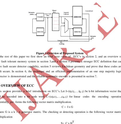
Figure 1.Overview of Proposed System
In the rest of this paper we first show an brief over- view of ECC’s in section 2, and an overview of
our fault tolerant memory system in section 3,and a section 4 presents a stronger ECC definition that can
have fault secure detector capability, section 5 reviews Euclidean geometry and prove that these codes are
fault secure. In section 6, the technique and an efficient implementation of an one step majority logic
corrector is demonstrated and the reliable systematic encoder is presented in section 7.
II. OVERVIEW OF ECC
This section provides a brief introduction on ECC’s. Let I=(i0,i1,….ik-1) be k-bit information vector that
will be encoded into n bit code word C=(c0,c1,….,cn-1) for linear codes the encoding operation
essentially per- forms the following vector matrix multiplication.
C = I x G
Where G is a k × n generator matrix. The checking or detecting operation is the following vector matrix
multiplication
S= C x HT
Where H is an (n-k) × n parity check matrix and the (n-k)bit vector.
S is called syndrome vector. A syndrome vector is zero if c is a valid codeword and non zero if c is an
erroneous codeword. A code word is a systematic code, if any codeword consist of the original k-bit information
vector followed by n-k parity it’s with this definition; the generator matrix of a systematic code must have the
following structure
Where I is a k x k identity matrix and X is a k×(n-k) matrix that generates the parity bits.
The advantage of using systematic codes is that there is no need for a decoder circuitry to extract the
information bits. The information bits are simply available in the first k bits of any encoded vector. A code is
said to cyclic code if for any codeword c all the cyclic shifts of c are still a valid code word. a code is cyclic
if the rows of its parity check matrix and the generator matrix are the cyclic shifts of their first rows. The
minimum distance of an ECC, d is the minimum number of code bits that are different between any two
code words. The maximum number of errors that an ECC can detect is d-1,and the maximum number that
it corrects is[d/2].any ECC is represented with a triple (n, k ,d) representing code length, information bit
length and minimum distance respectively.
III.SYSTEMOVERVIEW
Memory system design which can tolerate errors in any part of the system will be outlined in this section. Let
E be the maximum number of error bit s that the code can correct and D be the maximum number of error bits
that it can detect. Let ee, em, ec be the number of errors in encoder, memory word and corrector. In
existing design, the system would guarantee error correction as long as em ≤ E and ee, ec =0. In contrast we
guarantee that system can correct any error combination as long as em≤ E, ee,+ ede≤ D and em +ec+edc ≤
D, where edc, ede are the number of errors in two separate detectors, monitoring the encoder and corrector
units.
The proposed fault tolerant system with high fault tolerant capability is feasible when the following two
fundamental properties are satisfied
(a) Any single error in the encoder or corrector circuitry can only corrupt a single codeword digit (i.e.
cannot propagate to multiple codeword digits).
(b) There is FSD circuit which can detect any limited combination of errors in the received codeword or the
detector circuit itself.
Property (a) is guaranteed by not sharing logic between the circuitry which produces each bit. The property
(b) FSD is possible with a more constrained definition for the error correcting codes.
Error correction codes (ECC’s) are usually distinguished between convolution codes and block codes.
Convolution codes are processed bit by bit basis. They are particularly suitable for implementation in
hardware. Block codes are processed on a block by block basis .examples of block codes are repetition codes,
hamming codes, and multi dimensional parity check codes. Turbo codes and low density parity check codes
(LDPC) are relatively new construction that provides almost optimal efficiency. An overview of our
proposed reliable memory system is shown in figure 1 and described as follows. The block diagram consist
of following blocks namely encoder, corrector and memory block.
3.1 Encoder
The information bits are fed into the encoder to encode the information vector and the fault secure detector of
encoder verifies the validity of the encoded vector. If the detector detects any error, the encoding operation
3.2 Corrector
During memory access operation, the stored codeword will be accessed from the memory unit. Codeword’s
are susceptible to transient faults while they are stored in the memory. There for a corrector unit is designed to
correct potential errors in the retrieved code words. In our de- sign, all the memory words pass through
corrector and any potential error in the memory words will be correct- ed. Similar to the encoder unit, a
fault secure detector monitors the operation of the corrector unit.
3.3 Memory block
Data bits stay in memory for a number of cycles and during this period, each memory bit can be upset
by a transient fault with certain probability. Therefore, transient errors accumulate in the memory words over
time. In order to avoid accumulation of t o o many e r r o r s in any memory word t h a t s u r p a s s e s that
code correction capability, the system must perform memory scrubbing. Memory scrubbing is the process of
periodically reading memory words from the memory, correcting any potential errors and writing them back
into the memory. To perform the periodic scrubbing operation, the normal memory access operation is
stopped and the memory performs the scrub operation.
IV.ECC WITH FAULT SECURE DETECTOR
Reed Solomon codes have been suggested for single error fault tolerant encoder and decoder circuits. In this
the encoder is protected with the parity prediction and parity checker .The decoder is protected by adding a
code checker block and hamming distance counter block to count the number of error bits at the output of
decoder. If the code checker detects a non code word, then the error is detected. If the code checker detects a
codeword but the hamming distance counter indicates a non- zero error then an error is also detected. Here
we propose a multiple error fault tolerant encoder and decoder that is general enough for implementation
and for any kind of ECC that satisfies the restricted ECC definition. The restricted ECC definition which
guarantees a fault se- cure detector capable ECC is as follows.
Definition: Let c be an ECC with minimum distance d, C is FSD-ECC if it can detect any combination of overall
d-1 or fewer errors in the received codeword and in the detector circuitry
Theorem 1: Let C be an ECC, with minimum distance d, C is FSD-ECC if any error vector of weight 0< e ≤
d-1, has syndrome vector of weight at least d.
Proof: The core of detector circuitry is a multiplier that implements the vector matrix multiply of the received
vector and the parity check matrix to generate the syndrome vector .Now if e errors strike the received
code- word the syndrome weight of the error pattern is at least d-e from the assumption, Furthermore, the
maximum number of tolerable errors in the whole system id d-1 and errors already exist in the encoded
vector .therefore the maximum number of errors that can strike in the detector circuitry id d-1-e.these many
errors can corrupt at most d-1-e syndrome bit, which in worst case leaves at least one non zero syndrome bit
V.EUCLIDEAN GEOMETRY CODES
This section briefly review the Euclidean codes based on lines and points of the corresponding finite geometries.
Euclidean geometry codes are also called as EG-LDPC codes based on the fact that they are low density
parity check codes .LDPC codes have a limited number of 1’s in each row and column of the matrix .this
guarantee’s less complexity in the associated detectors and correctors making them fast and simple.
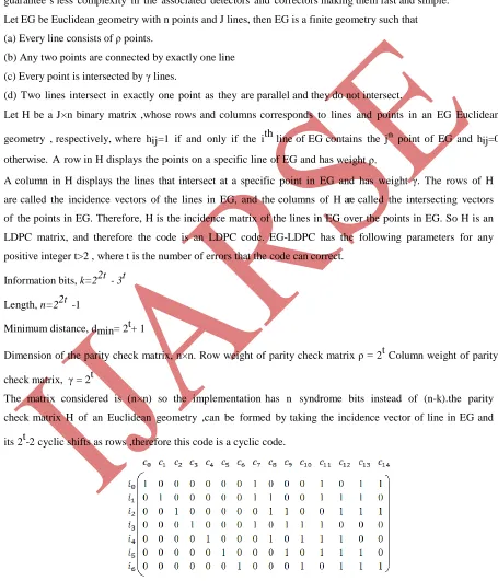
Let EG be Euclidean geometry with n points and J lines, then EG is a finite geometry such that
(a) Every line consists of ρ points.
(b) Any two points are connected by exactly one line
(c) Every point is intersected by γ lines.
(d) Two lines intersect in exactly one point as they are parallel and they do not intersect.
Let H be a J×n binary matrix ,whose rows and columns corresponds to lines and points in an EG Euclidean
geometry , respectively, where hij=1 if and only if the ith line of EG contains the jth point of EG and hij=0
otherwise. A row in H displays the points on a specific line of EG and has weight ρ.
A column in H displays the lines that intersect at a specific point in EG and has weight γ. The rows of H
are called the incidence vectors of the lines in EG, and the columns of H are called the intersecting vectors
of the points in EG. Therefore, H is the incidence matrix of the lines in EG over the points in EG. So H is an
LDPC matrix, and therefore the code is an LDPC code. EG-LDPC has the following parameters for any
positive integer t>2 , where t is the number of errors that the code can correct.
Information bits, k=22t - 3t
Length, n=22t -1
Minimum distance, dmin= 2t+ 1
Dimension of the parity check matrix, n×n. Row weight of parity check matrix ρ = 2t Column weight of parity
check matrix, γ = 2t
The matrix considered is (n×n) so the implementation has n syndrome bits instead of (n-k).the parity
check matrix H of an Euclidean geometry ,can be formed by taking the incidence vector of line in EG and
its 2t-2 cyclic shifts as rows ,therefore this code is a cyclic code.
Above Figure shows the systematic generator matrix to generate (15,7,5) EG-LDPC code. The encoded
vector consists of information bit followed by parity bits where each parity bit is simply an inner product of
information vector and a column of X.
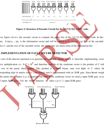
Figure 3: Structure of Encoder Circuit for the (15,7,5) EG- LDPC code .
Above figure s h o w s the encoder circuit to compute the parity bits of the (15,7,5) EG-LDPC code. In this
figure, I=(i0,i1,….i6) is the information vector and will be copied to C= (c1,c2,...c6) Bits of the encoded
vector C, and the rest of the encoded vector ,the parity bits are linear sums of the information bits.
VI. IMPLEMENTATION OF FAULT SECURE DETECTOR
The core of the detector operation is to generate the syndrome vector, which is basically implementing vector
matrix multiplication i.e., S=C x HT and therefore each bit of the syndrome vector is the product of C with
one row of the parity check matrix. This product is a linear binary sum over digits of C where the
corresponding digit in matrix row i s 1.the binary sum is implemented with an XOR gate. Since the row weight
of the parity check matrix is ρ, to generate one digit of the syndrome vector we need ρ input XOR gate, or
(ρ-1) 2 inputs XOR gates. For the whole detector, i t takes γ (ρ-(ρ-1) 2 input XOR gates.
An error is detected if any of the syndrome bit has non zero value. The final error detection signal is
detector signal. In order to avoid single point of failure, we have to implement the OR gate with the reliable
lithographic technology.
VII.ONE STEP MAJORITY LOGIC CORRECTOR
One step majority logic correction is a fast and relatively compact error correcting technique. The core of the
one step majority logic corrector is generating γ parity check sum from the appropriate rows of the parity
check matrix. There are few ECC’s known to be one step majority correctable, including t y p e –I 2
d i m e n s i o n a l E G -LDPC. These codes, the one step majority logic corrector corrects up to γ/2 error,
bits in the received encoded vector, by computing γ parity check sum of ρ code
bits each. Each parity sum is implemented with ρ input XOR function. The majority value of the parity
check sums are then evaluated with γ input majority gate. If the majority value is 1 then the code bit under
consideration holds an erroneous value and has to be inverted. For cyclic codes including EG, a single serial
majority corrector circuit can be used. For all the code bits, where the received encoded vector is cyclic
shifted and fed into the XOR gates to correct each code bit.
7.1 Parallel Corrector
For high error rates the corrector is used more frequently and its latency can impact the system
performance. Therefore parallel step majority corrector which is essentially n copies of the single
one-step majority-logic corrector is implemented.
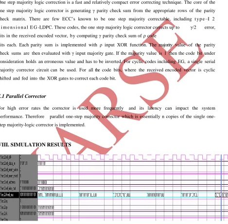
VIII. SIMULATION RESULTS
Figure 6: Simulation Results of FSED without Error at Output Side
IX.CONCLUSION
In this paper, we have developed a memory system that can tolerate and correct errors not only in the storage
unit but also in the supporting circuitry. We used Euclidean geometry codes. We prove that these codes are
FSD- ECC. Using these FSD we design a fault tolerant encoder and corrector, where the fault secure detector
monitors the operation.
REFERENCES
[1] ITRS, “International technology roadmap for semiconductors”, 2 0 0 5 . [ o n l i n e ] .
A v a i l a b l e : h t t p : / / w w w . i t r s . n e t / Links/2005ITRS/Home2005.htm
[2] R.G.Gallager , Low-Density Parity-Check Codes. Cambridge, MA:MIT Press,1963.
[3] Y.Kou, S.Lin,and M.P.C. Fossorier, “Low-density Parity Check Codes based on finite geometries
rediscovery and new results”, IEEE Trans.inf.theory,vol.47,no.7,pp,2711-2736,jul.2001.
[4] H. Naeimi and A. DeHon, “Fault secure encoder and decoder for memory applications,” in Proc. IEEE
Int. Symp. Defect Fault Tolerance VLSI Syst., Sep. 2007, pp. 409–417.
[5] H. Naeimi and A. DeHon, “Fault-tolerant nano-memory with fault se-cure encoder and decoder,”
presented at the Int. Conf. Nano-Netw.,Catania, Sicily, Italy, Sep. 2007.
[6] Y. Chen, G.-Y. Jung, D. A. A. Ohlberg, X. Li, D. R. Stewart, J.O. Jeppesen, K. A. Nielsen,
J. F. Stoddart, and R. S.Williams,“Nanoscale molecular-switch crossbar circuits,” Nan- otechnology,
vol.14, pp. 462–468, 2003.
[7] Y. Chen, D. A. A. Ohlberg, X. Li, D. R. Stewart, R. S. Wil- liams,J. O. Jeppesen, K. A. Nielsen, J. F.
Stoddart, D. L. Olynick, and E.Anderson, “Nanoscale molecular-switch devices fabricated by