An Investigation on the Holddown Margin using Monte-Carlo Algorithm
for the PWR Fuel Assembly
Sang Youn Jeon1), Nam Gyu Park1), Gyu Tae Choi1), and Hyeong Koo Kim1)
1) Korea Nuclear Fuel Co. Ltd., 493 Deogjin-Dong Youseong-Gu Daejeon, Korea
ABSTRACT
The holddown springs provide an acceptable holddown force against hydraulic uplift force absorbing the length change of the fuel assembly relative to the space between the upper and lower core plates in PWR. These length changes are mainly due to the thermal expansion, the irradiation growth and creep down of the fuel assemblies. The holddown forces were calculated for the leaf-type holddown spring considering geometrical data of fuel assembly and its components, length changes of the fuel assembly due to the thermal expansion, the irradiation growth, and the irradiation relaxation. The holddown spring forces were calculated deterministically and statistically to investigate the benefit of the statistical calculation method in view of holddown margin. The Monte-Carlo algorithm was used for the statistical holddown force calculation. The holddown forces and holddown margins were calculated for BOC(Beginning Of Cycle) and EOC(End Of Cycle) conditions of each cycle. The holddown margins were evaluated using holddown forces, fuel assembly weight, and hydraulic uplift forces.
INTRODUCTION
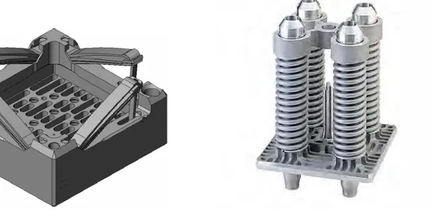
The holddown springs provide an acceptable holddown force against hydraulic uplift force absorbing the length change of the fuel assembly relative to the space between the upper and lower core plates in PWR. These length changes are mainly due to the thermal expansion, the irradiation growth and creep down of the fuel assemblies. There are two kinds of holddown springs depending on the different design concept of the reactor internals of the PWR in Korea, one is a leaf-type holddown spring for Westinghouse type plants and the other is a coil-type holddown spring for OPR1000(Optimized Power Reactor 1000). Fig. 1 (a) shows the configuration of the leaf-type holddown spring attached to the top nozzle of the fuel assembly. There are four sets of holddown springs in each fuel assembly for leaf-type holddown spring and each set of holddown springs consists of multiple tapered leaves to form a cantilever leaf spring set. The length, width and thickness of the spring leaves are selected to provide the desired spring constant, deflection range, and holddown force. Small amounts of permanent deformation can be occurred due to the plasticity, however the holddown springs are required to provide the desired holddown force subsequently to the occurrence of the permanent deformation[1,2]. Fig. 1 (b) shows the configuration of the coil-type holddown spring assembled in the top nozzle of the fuel assembly. There are four coil springs in each fuel assembly for coil-type holddown spring.
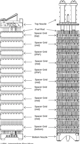
The holddown springs shall provide sufficient holddown force to ensure that the fuel assembly does not liftoff from core plate. However, higher holddown force can cause excessive fuel assembly bowing due to the axial compression load on the top of fuel assembly. Fig. 2 (a) and Fig. 2 (b) shows the configuration of the fuel assembly and its components for Westinghouse type and OPR1000 type plants, respectively[3,4].
(a) Top nozzle with leaf-type holddown spring (b) Top nozzle with coil-type holddown spring
Fig. 1 Configuration of the holddown springs attached to the top nozzles of fuel assemblies
* IFM : Intermediate Flow Mixer
(a) Fuel assembly with leaf-type holddown spring (b) Fuel assembly with coil-type holddown spring
Fig. 2 Configuration of the fuel assemblies
Top Nozzle
Fuel Rod
Spacer Grid (mid)
Bottom Nozzle Spacer Grid (top)
Spacer Grid (IFM*)
Spacer Grid (mid)
Spacer Grid (bottom) Spacer Grid (mid)
Spacer Grid (mid) Spacer Grid (IFM*)
Spacer Grid (mid) Spacer Grid (IFM*)
In this study, the holddown forces were calculated for the leaf-type holddown spring considering geometrical data of the fuel assembly and its components, length changes of the fuel assembly due to thermal expansion, irradiation growth, and irradiation relaxation. The holddown spring forces were calculated deterministically and statistically to investigate the benefit of the statistical calculation method in view of holddown margin. The Monte-Carlo algorithm was used for the statistical holddown force calculation. It was seen that more holddown margin exists when the statistical algorithm was applied, and the holddown margin increases are due to the statistical calculation of the fuel assembly length changes, growth, creep, and relaxation based on the 95% confidence level.
STRUCTURAL BEHAVIOR OF THE FUEL ASSEMBLY IN THE CORE
The structural behavior of the PWR fuel assembly is affected by the fuel assembly length change in the core. The fuel assembly length can be increased due to the thermal expansion and irradiation growth and decreased due to the creep down. The thermal expansion and irradiation growth of the fuel assembly are dependent on the temperature and fluence in the core. The amount of the creep down will be increased with the higher downward hold-down spring forces and upward hydraulic force. These thermal expansion, irradiation growth and creep down are major parameters for the evaluation of the fuel assembly length change and holddown force.
The irradiation growth is defined as a change in length without a volume change during irradiation in the absence of applied stress. The characteristics of the irradiation growth and creep down for the zirconium alloy are affected by the material dependent parameters such as texture, cold work, heat treatment, corrosion, etc. and core conditions dependent parameters such as neutron fluence, temperature, etc.[5,6] The spacer grids of nuclear fuel assembly support the fuel rods along their length and maintain the lateral spacing between the rods throughout the design life of the fuel assembly. The support system allows for different thermal expansion, creep and growth of the fuel rods, while maintaining sufficient spring contact force to prevent coolant flow-induced vibration damage. In general, the irradiation growth of the fuel rod is higher than that of the fuel assembly because of the higher neutron fluence and temperature. The higher irradiation growth of the fuel rod will cause tensional stress through a spacer grid spring force on the guide thimble within a span of the fuel assembly until the sliding takes place between the grid spring and fuel rod. The effect of the fuel rod irradiation growth on the fuel assembly growth will become severe for the fuel assembly design with higher grid spring forces. The spacer grid spring forces are reduced as a function of the fluence due to the irradiation induced stress relaxation. The stress relaxation of the spacer grid spring with Inconel alloy will be less than that of zirconium alloy. The fuel assembly design with all Inconel grid has strong fuel rod growth effect on the fuel assembly growth because of the less stress relaxation of the Inconel spring force.
ANALYSIS METHOD
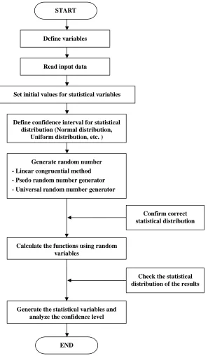
The Monte Carlo method was used for the statistical calculation of the holddown forces. The Monte Carlo method provides approximate solutions to a variety of mathematical problems by performing statistical sampling experiments on a computer. Monte Carlo method is a widely used class of computational algorithms for simulating the behavior of various physical and mathematical systems, and for other computations. Because of the repetition of algorithms and the large number of calculations involved, Monte Carlo is a method suited to calculation using a computer, utilizing many techniques of computer simulation. Monte Carlo algorithm is often used to find solutions to mathematical problems (which may have many variables) that cannot easily be solved. For many types of problems, its efficiency relative to other numerical methods increases as the dimension of the problem increases. Fig. 3 shows the analysis procedure of Monte Carlo simulation.
Fig. 4 shows the analysis procedure of holddown force using deterministic method. To calculate the holddown forces deterministically, the minimum and maximum spring deflections are established by stacking up dimensional tolerances, accounting for thermal expansion and irradiation growth effects of the fuel assembly and core support structure. The tolerance stacking is performed based on the square root of sum of squares method. The spring characteristics are determined based on a theoretical method or based on the test results of the specific holddown spring design. The minimum and maximum holddown spring forces are calculated using the minimum and maximum spring deflections and spring characteristics for each beginning and end of cycles.
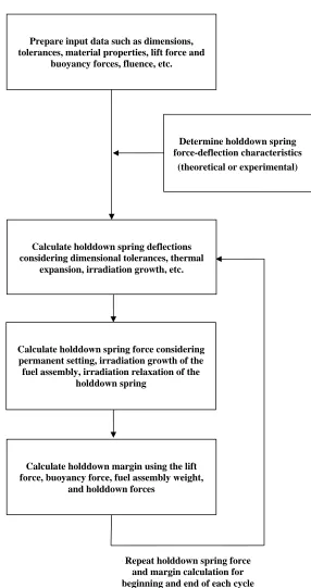
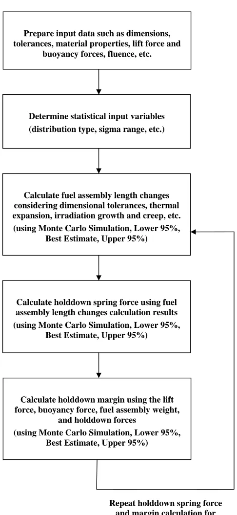
Fig. 5 shows the analysis procedure of holddown force using statistical method. The Monte-Carlo algorithm is used for the statistical calculation of fuel assembly length change, holddown force, and holddown margin. To calculate the holddown forces statistically, the statistical input variables are defined with the mean value, type of distribution, and range of sigma, etc. The fuel assembly length, holddown spring free height, and core plate distances are considered as statistical input variables with uniform distribution. The fuel assembly length changes and holddown forces are determined considering the irradiation growth, irradiation creep, elastic compression, etc. based on the 95% confidence level. The holddown margins are calculated using fuel assembly weight, lift force, buoyancy force, holddown force, and uncertainties based on the 95% confidence level.
Fig. 3 Procedure of the Monte Carlo simulation Define variables
START
Read input data
Define confidence interval for statistical distribution (Normal distribution,
Uniform distribution, etc. )
Generate random number - Linear congruential method - Psedo random number generator - Universal random number generator
Generate the statistical variables and analyze the confidence level Calculate the functions using random
variables
END
Set initial values for statistical variables
Confirm correct statistical distribution
Check the statistical distribution of the results
Fig. 4 Analysis procedure of the holddown force using deterministic method Prepare input data such as dimensions,
tolerances, material properties, lift force and buoyancy forces, fluence, etc.
Determine holddown spring force-deflection characteristics
(theoretical or experimental)
Calculate holddown spring force considering permanent setting, irradiation growth of the fuel assembly, irradiation relaxation of the
holddown spring
Repeat holddown spring force and margin calculation for beginning and end of each cycle Calculate holddown spring deflections
considering dimensional tolerances, thermal expansion, irradiation growth, etc.
Calculate holddown margin using the lift force, buoyancy force, fuel assembly weight,
and holddown forces
Fig. 5 Analysis procedure of the holddown force using statistical method Prepare input data such as dimensions,
tolerances, material properties, lift force and buoyancy forces, fluence, etc.
Determine statistical input variables (distribution type, sigma range, etc.)
Calculate holddown spring force using fuel assembly length changes calculation results (using Monte Carlo Simulation, Lower 95%,
Best Estimate, Upper 95%)
Repeat holddown spring force and margin calculation for beginning and end of each cycle Calculate fuel assembly length changes
considering dimensional tolerances, thermal expansion, irradiation growth and creep, etc. (using Monte Carlo Simulation, Lower 95%,
Best Estimate, Upper 95%)
Calculate holddown margin using the lift force, buoyancy force, fuel assembly weight,
and holddown forces
(using Monte Carlo Simulation, Lower 95%, Best Estimate, Upper 95%)
ANALYSIS AND RESULTS
The holddown forces were calculated for the leaf-type holddown spring considering geometrical data of fuel assembly and its components, length changes of the fuel assembly due to thermal expansion, irradiation growth, and irradiation relaxation. The holddown spring forces were calculated deterministically and statistically to investigate the benefit of the statistical calculation method in view of holddown margin.
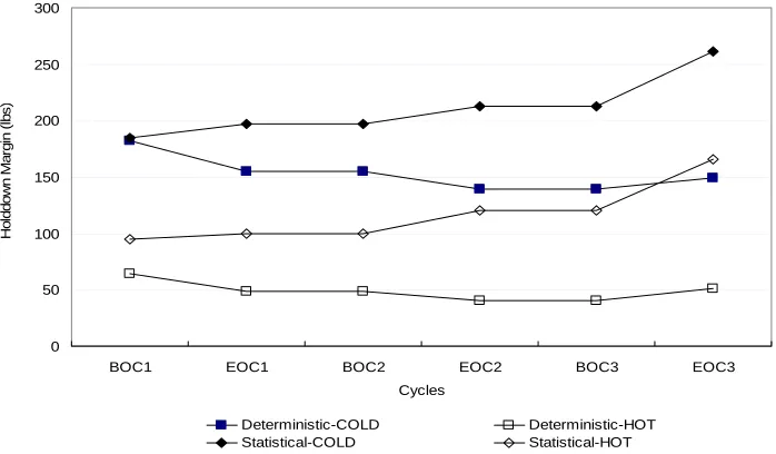
Table 1 and Table 2 show the calculation results of the holddown forces and holddown margins for BOC(Beginning Of Cycle) and EOC(End Of Cycle) conditions of each cycles, respectively. The holddown margins were calculated using holddown forces, fuel assembly weight, and hydraulic uplift forces. Fig. 6 and Fig. 7 show the comparison of minimum holddown forces and holddown margins between deterministic and statistical results for cold and hot conditions. It was seen that more holddown margin exists when the statistical algorithm was applied for both cold and hot conditions. The holddown margins with statistical method are about 1.3~2.0 times higher at cycle 1 and 2, 1.5~3.0 times higher at cycle 2 and 3 than holddown margins with deterministic method. It was evaluated that the holddown margin increases are due to the statistical calculation of the fuel assembly length changes, growth, creep, and relaxation based on the 95% confidence. The holddown margins with statistical method for cold and hot condition are increased as the number of cycle increases and the holddown margins with deterministic method for cold and hot condition are decreased as the number of cycle increases. The holddown margin decreases are due to the minimum combination of the dimensions and tolerances, the increased irradiation relaxation, and the increased permanent set of the holddown spring caused by the increased irradiation growth. The holddown margin increases are the result of statistical calculation for the key dimensions and tolerances. The minimum holddown margin take places at BOC1 when the statistical method is used and it take places at EOC2 and BOC3 when the deterministic method is used.
Table 1. Calculation results of minimum holddown forces (unit:lbs)
Items Deterministic Method Statistical Method
BOC1(Cold/Hot) 1,718/760 1,721/792
EOC1(Hot/Cold) 745/1,691 797/1,734
BOC2(Cold/Hot) 1,691/745 1,734/797
EOC2(Hot/Cold) 736/1,675 816/1,750
BOC3(Cold/Hot) 1,675/736 1,750/816
EOC3(Hot/Cold) 747/1,685 862/1,797
Table 2. Calculation results of minimum holddown margin (unit:lbs)
Items Deterministic Method Statistical Method
BOC1(Cold/Hot) 182/64 185/95
EOC1(Hot/Cold) 49/155 100/197
BOC2(Cold/Hot) 155/49 197/100
EOC2(Hot/Cold) 40/139 120/213
BOC3(Cold/Hot) 139/40 213/120
EOC3(Hot/Cold) 51/149 166/261
SUMMARY AND CONCLUSION
The holddown spring forces were calculated deterministically and statistically to investigate the benefit of the statistical calculation method in view of holddown margin. It was seen that more holddown margin exists when the statistical algorithm was applied for both cold and hot conditions. The holddown margins with statistical method are about 1.3~2.0 times higher at cycle 1 and 2, 1.5~3.0 times higher at cycle 2 and 3 than holddown margins with deterministic method. The minimum holddown margin take places at BOC1 when the statistical method is used and it take places at EOC2 and BOC3 when the deterministic method is used.
ACKNOWLEDGEMENT
This study was carried out under the project “Development of the Major Design Codes for a Nuclear Power Plant” which was funded by the Ministry of Commerce, Industry and Energy.
0 200 400 600 800 1000 1200 1400 1600 1800 2000
BOC1 EOC1 BOC2 EOC2 BOC3 EOC3
Cycles H ol ddow n F or c e (l bs ) Deterministic-COLD Deterministic-HOT Statistical-COLD Statistical-HOT
Fig. 6 Comparison of minimum holddown forces between deterministic and statistical results
0 50 100 150 200 250 300
BOC1 EOC1 BOC2 EOC2 BOC3 EOC3
Cycles H ol ddow n M ar gi n ( lbs ) Deterministic-COLD Deterministic-HOT Statistical-COLD Statistical-HOT
Fig. 7 Comparison of minimum holddown margins between deterministic and statistical results
REFERENCES
1. Dr Berenger d’Uston (2001). “Optimized Design of Holddown Springs with Bending Leaves,” Trans. Of the 15th International Conference on Structural Mechanics in Reactor Technology, Paper #1396, Washington DC
2. Yim, J. S., Joo, H. K. and Sohn D. S. (2001). “Analysis of Non-linear Spring Characteristics of Holddown Springs,” Trans. Of the 15th International Conference on Structural Mechanics in Reactor Technology, Paper #1940, Washington DC
3. KNFC, 16 Type ACE7™ Fuel Design and Safety Evaluation for KORI 2 Nuclear Power Plant, 2006 4. KNFC, PLUS7 Fuel Design and Safety Evaluation for Korean Standard Nuclear Power Plants, 2004 5. E. F. Ibrahimeral, Journal of Nuclear Material, Vol. 91, p. 31, 1980
6. R. G. Fleck et. Al, ASTH STP, Vol. 824, p. 88, 1982