121
In-Place Strength Evaluation of Jacket Platforms and
Optimization of Bracing Configurations
Faseela. A
1, Dr. Jayalekshmi. R
21
M.Tech Student, Civil Engineering Department, N.S.S College of Engineering, Palakkad 2
Professor, Civil Engineering Department, N.S.S College of Engineering, Palakkad
Email:[email protected]
Abstract- Fixed jacket platforms are huge steel framed structures used for the exploration and extraction of oil and gas from the earth’s crust. Jacket type structures are appropriate for relatively shallow water depth. These structures will be fixed to seabed by means of tubular piles either driven through legs of jacket or through skirt sleeves attached to the bottom. Since Jacket structures are very expensive, weight optimization could reduce their capital investment. This paper deals with the in-place analysis of an eight legged jacket platform at North Sea and optimisation of the bracing configurations by comparing the weight of jackets with different bracing configurations. Typical 6 bracing configurations are selected for optimization. The jackets are modeled in SACS finite element program and in-place analysis is conducted with fixed boundary conditions. Critical load conditions are taken into account, which include structure and equipment weight, wind load, hydrodynamic (wave & current) load using Morison equation. After in-place analysis, the members are redesigned by varying the diameter and thickness until stress ratio for similar members in 6 jacket configurations became equal to each other. The weight of jacket for each bracing configuration is determined, and the relevant bracing configuration of the jacket with minimum weight is selected as the optimum one.
Index Terms- Jacket, Offshore Platform, Bracing Configurations, In-place Analysis, SACS, stress ratio, Optimisation;
1. INTRODUCTION
Fixed jacket platforms are huge steel structures used for the exploration and extraction of oil and gas from the earth’s crust. These structures will be fixed to seabed by means of tubular piles either driven through legs of jacket or through skirt sleeves attached to the bottom.
The primary function of a jacket structure is to support the weight of the topside structure by transferring the weight to the foundation. The jacket structure must be designed to resist design environmental loads (from wind and waves) and also accidental loads, such as boat impact, extreme environmental conditions and earthquake.
A jacket structure typically consists of tubular members of various diameters and wall thicknesses. A typical jacket platform is shown in Fig.1. The air gap between the sea surface and the bottom of the topside structure is made high enough to prevent waves from hitting the topside structure. At the bottom, the jacket is normally outfitted with a temporary foundation which supports the jacket until the permanent foundation is installed. Bracing configurations consist of the vertical, horizontal and diagonal members which connect jacket legs forming a stiff truss system, transfer the loads acting on the platform to its foundation. There is a wide variation in platform bracing patterns which could be selected such as single diagonals, cross-braces, K-braces and combinations of these patterns. Several of these patterns are shown in Fig.2. Piles are typically used as
the permanent foundation, and are connected to the jacket by pile sleeves and grouted connections.
123 dimensioning of jacket bracings. Meanwhile, the
maximum overturning moment should be established for dimensioning of jacket legs.
2.2. Analysis Software
SACS (Structural Analysis Computer Systems), a Design and Analysis software for offshore structures and vessels, is used for the modeling and analysis of the jacket.
SACS is an integrated suite of finite element based software that supports the analysis, design and fabrication of offshore structures, including oil, gas, and wind farm platforms and topsides. Its ability to dynamically iterate designs allows users to perform advanced analysis, comply with offshore design criteria, and visualize complex results. SACS provides reliable beam member code checking and tubular joint code checking capacity; therefore it is very suitable for topsides structures consisting of plate girders and tubular columns/ braces.
2.3.Modelling Data
The jacket platform is eight-legged jacket for the purpose of supporting 25000 tones maximum operation weight located in Block 15/3 on the Norwegian Continental Shelf, at a water depth of 115 m. The total height of the jacket is 142.7 m and the jacket footprint at sea floor is 40m×60m and topside footing dimension is 26.2m×32.4m. The bracing pattern used is V- plus X- pattern (type 4 brace pattern). All the members are tubular with outside diameter varying from 2600mm to 700 mm and wall thickness from 75mm to 30 mm. Computer model of the Eight legged platform is shown in Fig.3.
Fig.3 : 3D Model in SACS
2.3.1. Material Property
The steel s420 is used for legs, piles and primary members and steel grade s355 is used for secondary members. The properties of are taken from NS-EN 10025-3. The material factor γm is 1.15 in ULS, which is indicated in NORSOK -004
2.4.Loading Data
2.4.1. Permanent Load and Variable Load
The permanent load includes the mass of the jacket and the topside weight. The topside weight is taken as equivalent load when an equipment box of 25000 tonnes is placed at the location of the topside.
2.4.2. Environmental Data
The environmental data (shown in Table.1 to table 4) is based on a meta ocean design report of an oil field located in Block 15/3. The hydrodynamic forces, wave and current forces are calculated using Stoke’s 5th order theory and Morison equation respectively. The wind force is applied as uniformly distributed on the surface of the topside and the effect of marine growth is accounted.
124 Table.2: Wave Height and period of wave with
100- year return period
Table.3: Thickness of Marine Growth
Table 4: Wind with 100 year return period
Where, U_0 is 1 h mean wind speed at 10 m height U_z is the1 h mean wind speed at height z(m) above sea level, u_z is the Characteristic wind velocity at height 40 m above sea level with corresponding averaging time period 15 sec, C_s is the Shape coefficient, A is the Surface area and F_w is the Wind force acting on the surface
2.4.3. Design Loads and Partial Load Factor
The design load model is based on permanent loads, variable loads, wave and current loads and wind loads. The ULS load combinations are split into eight ULS_A combinations and eight ULS_B combinations for a 100-year wind condition and a 100-year return period wave condition. The relevant factors of safety, according to NORSOK N-003, for ULS_A and ULS_B analysis are considered.
3. RESULT AND DISCUSSIONS
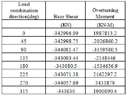
Linear static analysis is performed for the eight legged jacket considering 8 loading directions, 4 in orthogonal direction 0, 90, 180 & 270 deg. and 4 in diagonal direction i.e. 45, 135, 225 & 315 deg. Post, a sub program of SACS VI, is used to calculate element stresses and compare them to allowable stresses. The NORSOK-N003 code is selected to check stresses in the elements. The maximum base shear and overturning moment for ULS_A (for operational condition) and ULS_B (for extreme condition) analysis are shown in table.5 and table 6.
The comparison of base shears shows that the maximum base shear occurs in 90° and the maximum overturning moment in 270° in both operating and extreme conditions. i.e., the worst-case occurs while the environmental loads act from the south of the structure and the north of the structure. Unity check has been performed and found that the ratio of actual stress to allowable stress is less than unity for all members. Thus the structure is safe.
125 Table.6: Maximum Base Shear and Overturning
Moment for ULS_B analysis
Fig.4: Jacket weight for different bracing configurations
For the optimization, jacket has been remodeled for 5 other bracing configurations and analysed for the same loading conditions. The members are then redesigned by varying the diameter and thickness until stress ratio for similar members in 6 jackets became equal to each other and the weights of jackets are found. The weights of the optimised jackets are represented in chart form in Fig. 4. The chart shows that the jacket with Type 5 bracing configuration has the minimum weight and type 6 has the maximum weight among the 6 modeled jackets. The weight of jacket with type 5 bracing configuration is 26.4% less than the weight of jacket with type 6 bracing configuration. Thus type 5 bracing configuration is the optimum one.
4. CONCLUSION
Typical jacket in North Sea is modeled in SACS. It is analysed for environmental and operating conditions for the all load combinations given in DNV code and the base shear and overturning moments are found. The jacket has been remodeled for 6 different bracing configurations and optimization is carried out. The
comparison of the weight of optimized jackets shows that jacket with Type 5 bracing configuration has the minimum weight and thus Type 5 bracing configuration is the optimised bracing configuration.
Acknowledgments
I express my sincere gratitude to my guide Dr. Jayalekshmi R for her valuable guidance and advices. I also express my sincere indebtedness to Kavin Engineering And Services Private Limited, for giving me an opportunity to conduct internship in their consultancy firm. I would also like to thank the Department of Civil engineering, NSS College of Engineering and the almighty and my friends who have given us a lot of help and mental support for the timely completion of this work.
REFERENCES
[1] Arazi B. Idrus.; Narayanan Sambu Potty.; Zafarullah Nizamani.; (2011): Tubular Strength Comparison Of Offshore Jacket Structures Under API RP2A and ISO 19902. Journal - The Institution of Engineers, Malaysia.
[2] Bea.R.G.; T. Xu, J. Stear.; Ramos. R.; (1999): Wave Forces On Decks Of Offshore Platforms. Journal of Waterway, Port, Coastal, Ocean Eng. [3] Chakrabarti. S.; (2005): Handbook of Offshore
Engineering. Elserveir Ltd.
[4] Demir I. Karsan.; (1986): Design Of Jackets In Deeper Gulf Of Mexico Waters. Journal of Waterway, Port, Coastal, Ocean Eng, 112, pp.427-446.
[5] Lu Chai.; (2013): In-Place Strength Assessment of a Jacket and Effects of an Impact with a Floating Living Quarter (Flotel). University of Stavanger.
[6] Mohamed, A. E.; (2012): Offshore Structures Design, Construction and Maintenance. Elsevier. [7] Mohsen Mohammad Nejad.; (2010):
Optimization of Legs Batter in Fixed Offshore Platforms. Proceedings of 20th International Offshore and polar engineering conference. [8] Poonam Mohan.; Aswin Sidhaarth. K. R.; Sanil
Kumar. V.; (2013): Modeling And Analysis Of Offshore Jacket Platform. International Journal of Advances in Engineering & Technology. [9] Bentley official website :