The Embodied Conversational Agent Toolkit:
A new modularization approach.
R. J. van der Werf
Master of Science Thesis in
Human Media Interaction
Committee:
Prof. Dr. J. Cassell
Dr. D.K.J. Heylen
Dr. Z.M. Ruttkay
Prof. Dr. Ir. A. Nijholt
Human Media Interaction (HMI) Department of Electrical Engineering,
Mathematics and Computer Science University of Twente
The Netherlands
ArticuLab
School of Communication / School of Engineering Northwestern University United States of America
Preface
To obtain a master’s degree in Human Media Interaction a final research project has to be carried out. This research can be carried out both externally and internally. Before my final project I already carried out an internship of 14 weeks at the Institute for Creative Technologies (ICT) in Marina Del Rey, California. This internship abroad was very valuable; therefore I decided to also look abroad for my final research project. After I attended a presentation by Justine Cassell, I saw a lot of similarities with previous work I carried out during my master. After coming in contact with Justine Cassell I decided to do my research project under her supervision at the Northwestern University’s Articulab in Evanston, Illinois, USA.
At the Articulab there were two possible projects for me to work on. The first was along the lines of my previous internship which involved creating rapport with virtual humans. The second possibility was to work on a project for rapid prototyping of Embodied Conversational Agents (ECAs) which involved working with Panda3D and the graphical representation of ECAs. Since graphics and virtual reality have played an important role during my studies, the second possibility seemed like an ideal opportunity for me to further focus on these areas. I spent little over six months working on my research project at the Articulab. I soon found out that being part of this research lab involved a lot more then only working on my own project for six months. Every now and then the lab had to demonstrate their work to people, ranging from official demonstrations for faculty to presentations on ‘bring your daughter to work day’.
After my return to the Netherlands I also spent a lot more time on this project. The larger part of this time was used for the implementation. To resolve certain issues with the software I also paid a visit to the University of Bielefeld.
Looking back at the complete project I can say that I’ve had great experience doing research. From reading a lot of research papers to writing one. Both of which I didn’t really experience before. It has certainly made me think of pursuing a career in research in the future, which I didn’t consider before the start of this project.
First of all I would like to thank Justine Cassell and Dirk Heylen for providing me with this opportunity, for supporting me and keeping faith in me. In addition to Dirk Heylen I would like to thank Zsofi Ruttkay and Anton Nijholt for their time and feedback. Special thanks to Nathan Cantelmo, Jessica Cu, Francisco Iacobelli, Paul Tepper and John Borland for their help on this project. A thank also goes to the rest of my colleagues at the Articulab which made my visit to the Northwestern University a very pleasant one. Moreover I would like to thank Joris Janssen for both his personal and professional support during my time abroad and back home. From the University of Bielefeld I would like to thank Ipke Wachsmuth for giving his consent to use the Articulated Communicator Engine (ACE). Especially I want to thank Stefan Kopp for his guidance and support on ACE and for letting me visit the University of Bielefeld. Thanks also goes to Klaus Brügmann, Sebastian Ullrich and Helmut Prendinger for their information about MPML3D.
Abstract
This thesis shows a new modularization approach for Embodied Conversational Agents (ECAs). This approach is titled the Embodied Conversational Agent Toolkit (ECAT). ECAT builds upon the SAIBA framework, which proposed a three stage modularization of ECAs. ECAT focuses on the third stage, called behavior realization. The process of behavior realization can be summarized as: turning high-level behavior specifications into audiovisual rendering of an ECA. Internally this boils down to firstly converting high-level specifications into low-level specifications and secondly rendering these low-level specifications.
In between these two tasks is exactly where ECAT proposes a split. ECAT defines compilation as being the process of converting high-level specifications into low-level specifications and translation as the rendering of these low-level specifications. In addition to these two stages one preliminary stage is introduced called interpretation. Interpretation is meant to bridge between the wide variety of applications which are generating behaviors on the one hand and on the other hand the stage of compilation.
An ECA using ECAT uses one component for each stage: one Interpreter, one Compiler and one Translator. These three components are separated by two TCP/IP socket interfaces. This keeps the different components language and platform independent of each other. Both interfaces use XML languages for communication. The first interface currently uses the Multimodal Utterance Representation Markup Language (MURML). In addition to MURML this interface has future support for the Behavior Markup Language (BML), which is also used in the SAIBA framework. The second interface uses a custom markup language.
Table of Contents
Preface ___________________________________________________________________ ii Abstract __________________________________________________________________ iii Table of Contents __________________________________________________________ iv
List of Figures _________________________________________________________________ vi
List of Tables _________________________________________________________________ vii
1 Introduction ___________________________________________________________ 1
1.1 Introduction________________________________________________________________ 1
1.2 Embodied Conversational Agent systems ________________________________________ 2
1.2.1 NUMACK _____________________________________________________________________ 2 1.2.2 Sam / Alex _____________________________________________________________________ 3
1.3 A toolkit for rapidly creating ECAs ____________________________________________ 3
1.4 Approach and outline ________________________________________________________ 8
2 Existing ECA approaches _______________________________________________ 10
2.1 General___________________________________________________________________ 10
2.2 Behavior generation systems _________________________________________________ 11
2.3 Behavior realization ________________________________________________________ 13
2.4 Summary of modularization of ECA’s _________________________________________ 16
3 The Embodied Conversational Agent Toolkit (ECAT) _________________________ 19
3.1 (Additional) Modularization _________________________________________________ 19
3.2 Architecture Design ________________________________________________________ 20
3.3 High-level behaviors in a standard format ______________________________________ 21
3.3.1 MURML______________________________________________________________________ 22 3.3.2 BML _________________________________________________________________________ 25
3.4 Low-level behaviors in a standard format ______________________________________ 26
3.4.1 The requirements _______________________________________________________________ 26 3.4.2 Choosing a format ______________________________________________________________ 26
3.5 The three stages of ECAT ___________________________________________________ 29
3.5.1 Interpretation __________________________________________________________________ 29 3.5.2 Compilation ___________________________________________________________________ 31 3.5.3 Translation ____________________________________________________________________ 32
4 A proof of concept prototype _____________________________________________ 35
4.1 NUMACK’s Brain Interpreter _______________________________________________ 35
4.1.1 The Input _____________________________________________________________________ 35 4.1.2 Global system description_________________________________________________________ 35 4.1.3 The architecture ________________________________________________________________ 36 4.1.4 Separation between Brain and Body_________________________________________________ 37 4.1.5 The Interpreter _________________________________________________________________ 38 4.1.6 The output_____________________________________________________________________ 38
4.2.1 Articulated Communicator Engine (ACE) ____________________________________________ 39 4.2.2 Compiler Architecture ___________________________________________________________ 41
4.3 Open Inventor Translator ___________________________________________________ 45
4.3.1 The input______________________________________________________________________ 45 4.3.2 The translator __________________________________________________________________ 46 4.3.2 The output_____________________________________________________________________ 48
5 Additional ECAT components (under development) _____________________________ 49
5.1 WOZ Interpreter___________________________________________________________ 49
5.2 Ogre3D translator __________________________________________________________ 49
5.3 TGS Open Inventor translator _______________________________________________ 50
5.4 Panda3D translator_________________________________________________________ 50
6 Evaluation ______________________________________________________________ 53 7 Conclusion ______________________________________________________________ 54 8 Recommendations ________________________________________________________ 55 References________________________________________________________________ 56 Appendices _______________________________________________________________ 61
Appendix A: Original NUMACK Skeleton ________________________________________ 61
Appendix B: Partial Scenegraph of the NUMACK Skeleton __________________________ 67
Appendix C: Partial Max.xml ___________________________________________________ 71
List of Figures
Figure 1 General structure for a multimodal behavior generating system [12] ... 1
Figure 2 NUMACK and Sam (/ Alex) ... 3
Figure 3 The split in behavior realization proposed by the ECA Toolkit ... 4
Figure 4 possible high-level behavior specifications ... 4
Figure 5 simplified low-level description of wave gesture ... 5
Figure 6 Utility functions for joint rotations and audio playback ... 7
Figure 7 The three modules of the Embodied Conversational Agent Toolkit (ECAT) ... 8
Figure 8 ECAT with relation to the three stages of SAIBA... 10
Figure 9 Architecture of the MPML3D framework [51] ... 11
Figure 10 Example of an MPML3D behavoir ... 12
Figure 11 Architecture of Behavior Expression Animation Toolkit (BEAT) [16] ... 12
Figure 12 Architecture of the NVBGenerator [44] ... 13
Figure 13 Example MURML utterance referring to a gesture from a gesticon ... 13
Figure 14 REA architecture [13]... 14
Figure 15 High and Low level commands in Pantomime [17] ... 14
Figure 16 Rapport Agent architecture, using Smartbody for behavior realization [22] ... 15
Figure 17 Gesture Engine architecture, used in the Greta agent [26] ... 16
Figure 18 Existing ECA approaches w.r.t. the scope of ECAT ... 18
Figure 19 ECAT Architecture ... 20
Figure 20 Gesture phases ... 21
Figure 21 Example MURML specification [35] ... 22
Figure 22 the three body planes [35]... 23
Figure 23 Core BML which’s elements can be extended or new elements can be added. [69] ... 25
Figure 24 Example BML description [69] ... 26
Figure 25 joint rotation specified in COL ... 27
Figure 26 audio playback specified in COL... 28
Figure 27 Rotation format of the Compiler Output Language (COL) ... 28
Figure 28 DTD for the Compiler Output Language (COL) ... 29
Figure 29 Four types of possible input behaviors mapped with example output... 31
Figure 30 Start of sample interaction with NUMACK ... 35
Figure 31 NUMACK Architecture [63] ... 36
Figure 32 Microplanning architecture [14,40,65] ... 37
Figure 33 The BEAT architecture [16] ... 38
Figure 34 Example MURML Utterance from NUMACK’s Brain ... 39
Figure 35 The states of execution of a chunk [41]... 40
Figure 36 ECAT-Compiler architecture, shown in relation to ACE and the outer ECAT components... 42
Figure 37 Scenegraph representation of original ‘geometry data’ versus new ‘joint data’ ... 45
Figure 38 COL Example ... 46
Figure 39 Class diagram of the Open Inventor Translator... 46
Figure 40 Examiner Viewer showing the scenegraph... 47
Figure 41 The result, showing a ‘go left’-gesture. ... 48
Figure 42 WOZ-Panel for Sam / Alex [22]... 49
Figure 43 Class diagram of the Panda3D Translator ... 50
Figure 44 Panda3D model controlled by ‘ECAControl’... 51
List of Tables
Table 1 Classes of High-level behaviors... 5
Table 2 Classes of Low-level behaviors ... 6
Table 3 Typical elements needed for “Hi Æ Lo” ... 7
Table 4 Symbolic values which can be used for gesture descriptions in MURML [35] ... 24
Table 5 Interpreter functionality ... 29
Table 6 Compiler functionality ... 31
Table 7 Translator functionality... 32
Table 8 ACE-classes shown from base class to most specialistic class... 44
1 Introduction
1.1 Introduction
Embodied Conversational Agents (ECAs), also know as Virtual Humans (VHs), have been around for over a decade. ECAs are in essence agents. According to Wooldridge [70] an agent is: an encapsulated computer system that is situated in some environment and that is capable of flexible, autonomous action in that environment in order to meet its design objectives. According to Russell and Norvig [58] an agent is: “anything that perceives its environment through sensors and acts upon that environment through effectors”. Within this definition humans can also be seen as agents. ECAs are in fact agents in the form of Virtual Humans which are able to converse with humans using multimodal input and output. Input is most commonly gathered using sensors like, microphones and cameras, while output modalities are similar to those used in human to human conversation, like speech and gesture. ECAs have proven to be useful for different applications such as in training scenarios [28,34], for studying human behavior [14] as well as being an intuitive interface for Human Computer Interaction [18].
More recent, in addition to the development of these applications, researchers also have focused on working towards a modular architecture and interface standards, which would make it possible to more easily share and reuse each other’s work [23]. However a lot of approaches from the past years have introduced almost just as many markup languages for specifying behaviors of ECAs (Among which APML, RRL, PAR, MPML, etc. [12,20,54,56]). Efforts working towards interface standards from Vilhjalmsson and Marsella [46] and more recent from Kopp et. al. [38] have introduced the SAIBA framework. They show a three stage framework which lays down a general structure for every multimodal behavior generation system (see Figure 1).
Figure 1General structure for a multimodal behavior generating system [12]
A common issue with many ECA systems is the fact that the behavior realization module is often implemented as one monolithic component or as a multiple components which are so tightly coupled that it’s often hard to untangle them. NUMACK [65], a direction giving ECA, uses a behavior realization component know as the Articulated Communicator Engine (ACE) [41], which renders an ECA using a behavior description as input. The behavior realization component used at the Institute for Creative Technologies (ICT) and the Information Sciences Institute (ISI) is called Smartbody [66]. Smartbody is also capable of rendering ECAs using behavior specifications. The animation engine mentioned in the MPML3D framework [51] has even more responsibilities in addition to rendering an ECA using behavior specifications. All these systems rely on a graphics engine, or better said a rendering or game engine1.
NUMACK for instance uses Open Inventor [1], the Virtual Humans using Smartbody use
1 Rendering not only involves graphics, but also audio, therefore the term game engine is also used for: the engine
Unreal Tournament [2] and the MPML3D framework uses a self-made engine which uses OpenGL [3] and OpenAL [4]. Some of these engines require expensive licenses which makes them unsuited for a lot of researchers. To be able to share one’s behavior realization component with other researchers this component has to be decoupled from the rendering engine.
The field of research concerned with ECAs is composed of a diverse group of interested parties. Among computer graphics experts this includes a large number of linguists, psychologists, and artificial intelligence researchers who may have little or no professional interest in the field of computer graphics per se. Most of these researchers would like nothing more than for their virtual humans to be expressive and easy to control, without retaining a dedicated computer science/graphics researcher on staff. Ideally one wants to focus on their own research without having to be bothered with the rest of the agent. A psycholinguistic researcher may be interested in how people respond to backchannel behavior [24] in the form of a subtle head nod. However this very same researcher does not want to be bothered with the animation of these head nods.
Up until now most systems have focused on the representation of the knowledge structure of multimodal behavior, like the markup languages mentioned above. Most often the different sub-modules of these systems are tailored for the specific system which makes them not directly usable as a module for a different system.
Other systems have focused mainly on the behavior realization component (ACE [41], Gesture Engine [25], Pantomime [17], SmartBody [66]). Most often these systems are to a lesser extent designed to support a wide variety of rendering engines. Also these systems are less suitable to be used as a component to be used with a different behavior generation component.
This thesis describes a framework called the ECA Toolkit. ECAT can be seen as a behavior realization system consisting of multiple (open-source) components which can be shared among researchers. A proof of concept prototype has been implemented using parts of existing ECAs. This prototype will also be discussed in this thesis and can serve as a base for future implementations.
1.2 Embodied Conversational Agent systems
The implementation described in this thesis uses (parts of) two existing Embodied Conversational Agent (ECA) systems which are used in the ArticuLab [5]. A short description of these systems will be given here. The architectures and the modules used for ECAT will be discussed in more detail in chapter 3, 4 and 5.
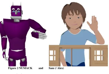
1.2.1 NUMACK
Figure 2NUMACK and Sam (/ Alex)
1.2.2 Sam / Alex
Sam and Alex are ECAs which interact with children; both projects are sub-projects of the Virtual Peer (VP) project [64]. The VP project uses an ECA, controlled by a Wizard of OZ (WOZ) interface [47], to engage in collaborative storytelling with children, these ECAs are animated using Adobe Flash. The project aims to promote development of language skills of children. Alex’s physical appearance is designed to be gender and race ambiguous; however both verbal and nonverbal behaviors are based on models of African American children. Sam’s physical appearance is designed to be gender ambiguous. The original Sam was developed at MIT [60] and was an autonomous ECA, the current version is also used to collaborate with children with autism. Especially for research on children with autism, this project also focuses on story authoring. More specific it will enable children to control, build and finally interact with the VP.
1.3 A toolkit for rapidly creating ECAs
Recent research in the Virtual Peer project [30] (also see 1.2) raised the need for additional animations for Alex. With the current implementation, in Adobe Flash, it’s quite cumbersome to change existing animations or to update existing ones. For this reason it was decided to create a new behavior realization component for the VP project.
The Embodied Conversational Agent Toolkit (ECAT) project was started to tackle this issue. It aims to minimize time spend on decoupling and refactoring ECA components, hereby facilitating rapid integration of (new) components and the construction of ECAs as a whole. The SAIBA framework (see 1.1) already proposes three stages which generally lay down the structure of an ECA. The third stage of behavior realization also includes the audiovisual rendering of an ECA, which can be seen as the end result or the output. Systems such as ACE [41] and Smartbody [66] are often integrated with a rendering engine to form the complete behavior realization component. ECAT makes a clear separation within the process of behavior realization. It decouples on the one hand: the conversion of high-level behavior specifications into low-level directives for animation and on the other hand: the rendering of these low-level directives (see Figure 3).
Figure 3 The split in behavior realization proposed by the ECA Toolkit
Before going into both subtasks of behavior realization, the meaning of high-level and low-level behaviors will be discussed first.
Figure 4 shows an example of what such high-level specifications might look like.
-Say(“Hello my name is Harry”) & Gesture(“wave”)
-Say(“Take <emphasis>this</emphasis> ball”) & Gesture(grab(“ball”)) -Say(“And who are you?”) & LookAt(“Person2”) & Gesture(“slouchRight”) -Say(“What is your name?”)
-Say(“That’s funny”) & ShowEmotion(“Smile”) -Gesture(“Headnod”)
-Say(“Hello there, how are you doing?”) & Gesture(“wave”) & ShowEmotion(“Smile”) -Say(“And next you make a right.”) & Gesture(“Make_a_right”)
Figure 4 Possible high-level behavior specifications
The behaviors shown above are typically the result of the behavior planning stage of the SAIBA framework. Similar to the SAIBA framework Tepper et. al. [65] define three subtasks in the generation of coordinated language and gesture. They refer to these tasks as 1) Content planning, 2) micro planning and 3) surface realization. These three tasks are very similar to the three stages of the SAIBA framework. In fact the three tasks or stages could be seen as: 1) figuring out what to communicate, 2) how to communicate it and 3) communicate it [65]. An example would be:
1) Greet,
2) Say(“Hello my name is Harry”) & Gesture(“wave”) and
3) ‘speaking and gesturing’.
High-level behavior specifications will henceforth be referred to as the behavior specifications resulting from stage 2: behavior planning, which can be used as input for stage 3: behavior realization. It’s important to note that timing information of different co-occurring behaviors (such as speech and gesture) is also specified in a high level specification. This can vary from behaviors being specified to be executed parallel (like in Figure 4) or in sequence, but it’s also
Behavior realization
High-level behaviors
Æ
Low-level behaviors
Low-level behaviors
Æ
possible to have more fine grained timing information. Gestures can for instance be specified to start when a certain word is uttered.
High-level behaviors can be divided into four classes, as is shown in Table 1. Every behavior in Figure 4 can be divided into one of these four classes.
Classes of
High-level behaviors:
Examples:
Gestures Head, body and limb gestures
Gaze Look at someone/something
Text + paraverbals Text to be spoken with optional paraverbal information such as emphasis, intonation and tone.
Facial expressions Happy, sad, angry, surprise, disgust
Table 1 Classes of High-level behaviors
On the other hand, low-level behaviors are defined on a much lower level of abstraction as the corresponding high-level behavior. The wave gesture mentioned in Figure 4 may for instance take two seconds to complete. Figure 5 shows a simplified list of low-level descriptions corresponding to: Say(…) & Gesture(“wave”) from Figure 4.
At t=0.0s
-Play(hello.wav) At t=0.2s
-Rotate(l_elbow,y,30) //Rotate arm up
-Rotate(l_elbow,z,90) //Rotate arm around to make palm face forward At t=0.4s
-Rotate(l_elbow,y,60) //Rotate arm up At t=0.6s
-Rotate(l_elbow,y,115) //Rotate arm up At t=0.8s
-Rotate(l_elbow,x,40) //Rotate arm to the right At t=1.0s
-Rotate(l_elbow,x,60) //Rotate arm to the right -Rotate(l_wrist,x,15) //Rotate wrist to the right At t=1.2s
-Rotate(l_elbow,x,40) //Rotate arm back to the left
-Rotate(l_wrist,x,0) //Rotate wrist back to default orientation At t=1.4s
-Rotate(l_elbow,x,0) //Rotate arm back to default orientation At t=1.6s
-Rotate(l_elbow,x,-40) //Rotate arm to the left At t=1.8s
-Rotate(l_elbow,x,-60) //Rotate arm to the left -Rotate(l_wrist,x,-15) //Rotate wrist to the left At t=2.0s
-Rotate(l_elbow,x,-40) //Rotate arm back to the right
-Rotate(l_wrist,x,0) //Rotate wrist back to default orientation
Figure 5 Simplified low-level description of wave gesture
therefore audio playback is started at t=0.0s. At t=0.0s the gesture is also started. In a real world example the gesture would oftentimes be timed to start before the speech. This way the most effortful part of the gesture will co-occur with the speech which is affiliated with the gesture. The specifications in Figure 4 and Figure 5 merely serve to demonstrate what high and low-level behaviors might look like. More complex examples, with more fine-grained timing, will be shown in chapter 3.
Low-level behavior descriptions can be divided into three classes as shown in Table 2.
Classes of
Low-level behaviors:
Examples:
Joint rotations Rotate(l_elbow,x,90) Audio playback directives Play(hello.wav)
Facial deformations DeformFaceMuscle(r_orbicularis_oculi, 0.1)
Table 2 Classes of Low-level behaviors
An important difference between high and low-level descriptions is that a high-level description defines a complete behavior, while a low-level description defines only the characteristics of this behavior for one frame.
As has been mentioned above the third stage of behavior realization can be split into two steps:
1. Hi Æ Lo
Converting high-level specification into low-level ones 2. Lo Æ Rendering
Rendering these low-level specifications
The discussion above has shown what is meant by high-level and what is meant by low-level behaviors. The first step inside the stage of behavior realization involves conversion of the former to the latter.
High-level behaviors specify a complete behavior and low-level behaviors specify only the characteristics per frame. This means the process: “Hi Æ Lo” involves filling in the blanks. This is oftentimes done by using a gesture database or a gesture lexicon, which will henceforth be referred to as gesticon. A gesticon contains a number of (low-level) gesture specifications, where the specific joint rotations are specified for every keyframe. Such specifications are most often exported from animation packages such as: Maya or 3D Studio Max.
A keyframe representation of a gesture only gives the low-level specification at certain, important, frames. To be able to create low-level specifications for every frame a smooth transition has to be made between keyframes. In addition to a smooth transition between subsequent keyframes, subsequent gestures also need to be blended smoothly. Blending between subsequent gestures is not as trivial as it may seem, because the end pose of one gesture may be very different from the start pose of the next gesture.
Generation of speech however is a completely different ball game. In fact an audio playback directive like: play(hello.wav) could be seen as higher level of abstraction as the
specification: say(“hello my name is Joe”). However, for a computer it’s easier to play a
wave-file than to speak. In the process of “Hi Æ Lo” the high-level text is used by a text-to-speech (TTS) synthesis system to generate the text-to-speech. The TTS system also provides phoneme timings which can be used for cross-modal synchrony.
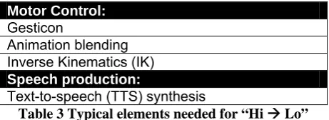
Table 3 shows a summary of elements which are typically needed for “Hi Æ Lo”, which have been mentioned above.
Motor Control:
Gesticon
Animation blending Inverse Kinematics (IK)
Speech production:
Text-to-speech (TTS) synthesis
Table 3 Typical elements needed for “Hi Æ Lo”
The second step (see Figure 3) within the process of behavior realization referred to as “Lo Æ
Rendering” will be discussed in the following.
The separation of Hi Æ Lo and Lo Æ Rendering can be particularly useful because most of the presently used engines2 for ECA representation have utility functions to play audio or to
apply joint rotations (see Figure 6) to the ECA’s body model. Thus these engines could well be used to turn low-level behavior descriptions into an audio-visual representation.
Panda3D[6]:
jointNode = actor.controlJoint(None,"modelRoot","l_elbow") jointNode = setHpr(h,p,r);
helloSound = loader.loadSfx("hello.wav") helloSound.play()
Ogre3D [7] (with FMOD Soundmanager): Bone b = skeleton.getBone(“l_elbow”); b.setOrientation(w,x,y,z);
helloSound = soundMgr->CreateSound(String(“hello.wav”)); int channel;
channel = soundMgr->PlaySound(helloSound,sceneNode, &channel);
Figure 6 Utility functions for joint rotations and audio playback
With utility functions listed in Figure 6 the above-mentioned task “Lo Æ Rendering” is in fact a relative simple task which can be divided into two simple steps. The first being: parsing low-level behaviors specified in a predefined format. The second being: using utility functions to render these behaviors.
On the other hand, the complete task of turning high-level descriptions into rendering (behavior realization) is much more complex. The complexity mainly resides in the task: “Hi
Æ Lo” which has been discussed above.
The complete task of behavior realization has been focused on by recent research [41,51,66]. Since these behavior realization systems are integrated with game engines they internally use
2This could be any engine ranging from Ogre3D, Panda3D, AgentFX . It could also be a self tailored engine using a graphics
utility functions like the ones listed in Figure 6. The parameters for these functions correspond to the ones found in low-level specifications. Therefore a behavior realization system needs some form or internal representation for these parameters. Because this internal representation is needed it’s a logical next step to create two different modules: firstly creating the low-level specification and secondly rendering this low-level specification.
The Embodied Conversational Agent Toolkit (ECAT) proposed in this thesis builds upon this modular separation of the process of behavior realization. The toolkit consists of three components (see Figure 7), most often the core component (responsible for “Hi Æ Lo”) can be kept static (marked grey in Figure 7), while the outer components are more likely to be replaced by alternatives. The two outer components are responsible for relative simple tasks which makes them easier to replace by new or other parts. The first of these two outer parts is responsible for turning a behavior specification into a standard format and the second is responsible for: “Lo Æ Rendering”.
Figure 7 The three modules of the Embodied Conversational Agent Toolkit (ECAT)
1.4 Approach and outline
The main focus of this thesis will be the Embodied Conversational Agent Toolkit (ECAT) which has been introduced in the previous section. When adopted by enough researchers a repository of modules can be built and used to easily share and reuse each other’s work. This repository will mainly contain modules for the two outer components, but can also contain modules which can be used as core component. An example of the first component would be: “A BML to MURML converter”3. Systems like Smartbody or ACE can be used as a base for
the core component. The third component could be “A renderer of low-level behaviors using Panda3D”.
Using this approach ECAT aims to facilitate rapid integration, sharing and prototyping of different ECA components, for either developing new ECA systems or updating parts of existing ones.
The work presented in this thesis shows my work during my final master project. The project was started due to the need for a new system for the Alex agent (see beginning of section 1.3).
3 These are both markup languages which will be discussed in greater detail in the remainder of this thesis High-level behaviors
in a custom format
Module 1
High-level behaviors in a standard format
Module 2
Low-level behaviors in a standard format
My work started from the first outline, which was already present. This outline included the three modules shown in Figure 7. I started my approach by first studying existing ECA architectures (chapter 2). The results of this study were then used to create a more detailed design of the toolkit and its components (chapter 3). Using this design the end goal was to implement a proof of concept prototype (chapter 4). The prototype components can serve as a base for future development.
ECAT is destined to be the toolkit to be used for future ECAs in the Articulab [5]. For the proof of concept it was chosen to reuse parts of existing systems. For this reason the larger part of my work involved studying and reusing existing software (section 4.1 and 4.2.1). To let it function within ECAT it also involved modifying this software (section 4.1.5, 4.2.2, 4.3, 5.1). To a lesser extend it also involved creating new software components completely from scratch (section 5.2-5.4).
Because the larger part of ECAT builds upon existing software (4.2.1) and existing standards (section 3.3.1 and 3.3.2) the discussion in this thesis will also contain content about work not directly carried out by me during this project. Understanding this work was an important task to eventually being able to reuse parts of it; to get a working proof of concept prototype. In a similar manner the discussion about ECAT cannot be a complete one, without including parts about (re)used work (section 3.3, 4.2.1).
2
Existing ECA approaches
2.1 General
For over five years research on modular ECA design has found a growing support [23]. Efforts working towards interface standards from Vilhjalmsson and Marsella [46] have proposed the interface languages FML and BML. More recent work from Kopp et. al [38]. has introduced the Situation, Agent, Intention, Behavior, Animation (SAIBA) framework, which uses these interface languages. In the authors' words, SAIBA was designed to provide “a powerful, unifying model of representations for multimodal generation.”[38]. To frame the generation process in terms of a general structure, the authors describe a three-stage behavior production model (also see Figure 1) consisting of:
(1) communicative intent planning, (2) multimodal behavior planning, (3) behavior realization
As the SAIBA framework contains three stages, two interfaces are needed in order to bridge the entire system. The SAIBA authors are primarily concerned with producing a pair of standard data markup languages for these interfaces. Of these two markup formats, early efforts have been focused on the second bridge, connecting behavior planning and behavior realization systems. This markup format has been named BML (for the Behavior Markup Language).
In a similar way Poggi et. al. make a separation of mind and body in their design of Greta [55]. In this sense the mind can be compared to stage 1 (and in partially stage 2) of the SAIBA framework, where the body can be compared to the remainder of framework.
Since the SAIBA framework lays down a general structure for the design of in fact any ECA, the term behavior realization will be adopted and used for the final stage. The distinction between the first two stages isn’t relevant to the discussion in this thesis; therefore both stages combined will be referred to as behavior generation.
The ECA toolkit (ECAT) which has been introduced in the previous chapter and which will be discussed in the remainder of this thesis ties into the very end of the process of behavior generation and is responsible for behavior realization of ECAs (see Figure 8). With this in mind the next section will focus on behavior generation systems, which illustrates where ECAT can tie into existing systems. The final section of this chapter will discuss behavior realization systems which could be used at the heart of ECAT, since they share a common goal. They all aim to realize generated behaviors.
Figure 8 ECAT with relation to the three stages of SAIBA
Behavior Generation
(stages 1,2)
Behavior Realization
(stage 3)
2.2 Behavior generation systems
The MPML3D authoring language provides a means for abstracting elements of the content creation process for interactive agent systems [51]. This approach is motivated by a desire to support digital content creators in the production of highly interactive and appealing content with a minimum of effort. MPML3D is the successor to MPML (the Multimodal Presentation Markup Language) [31,56], adding support for interactivity and greatly simplifying the language design to make it more accessible to non-experts. The architecture of the MPML3D framework (see Figure 9) is divided into three parts: user layer, developer layer and animation engine.
Figure 9 Architecture of the MPML3D framework [51]
The content creation for interactive presentations resides in the user layer. This is where the complete interactive scenario is stored. Behaviors (like the one in Figure 10) can be set to be executed when a user interacts or when another agent does a certain action. The behavior in Figure 10 is started when a user presses a key. Another possibility would be to trigger the start of the task when another agent finishes his introduction.
The developer layer is an intermediate layer which uncouples the user layer from particular implementations [51]. At runtime this layer is responsible for parsing the content selected from the complete interactive scenario. Also the agent’s states are defined in this layer, which correspond to their available actions.
The animation engine is responsible for handling the interaction with the user and the animation of the interactive scenario.
Basically user interactions (animation engine) can trigger new tasks (the user layer), which causes the actions inside the task to be issued (developer layer), which on its turn sends a rendering request to the animation layer.
The animation engine, together with the developer layer, can be seen as a behavior realization system, because these two parts ‘realize’ the behaviors generated in the user layer. On the other hand, the user layer where the MPML3D content is created or generated can be seen as a behavior generation system.
uses Second Life4, which is an online virtual world. In this world people can control avatars to
interact with each other. With the new MPML-SL it is also possible to interact with agents driven by an interactive scenario.
<Task name="introTask" priority="0" startOn="startKeyStroke"> <Sequential>
<Action class="gesture">
<Property name="type">BowVeryPolite</Property> </Action>
<Parallel>
<Action class="speak">
<Property name="text">Hi, my name is Naomi Watanabe.</Property> </Action>
<Action class="focus">
<Property name="target">User</Property> <Property name="angle">-5.0</Property> </Action>
</Parallel> </Sequential> </Task>
Figure 10 Example of an MPML3D behavoir
The Behavior Expression Animation Toolkit (BEAT) [16] can also be considered to be a behavior generation system. In the author’s own words, behavior generation is the core component in the BEAT architecture (see Figure 11). BEAT aims to assist animators by adding appropriate nonverbal and paraverbal behaviors to plain-text segments of dialogue that it receives as input. In order to perform this task, BEAT produces behaviors that are first synchronized with synthesized speech and then stored internally as abstract behavior specifications. In its final processing stage, BEAT translates these internal behavior representations into a customizable format that may then be used by a particular behavior realization engine (such as ACE, Gesture Engine, or Pantomime, all discussed in the next section). Thus, BEAT is best described as a multimodal behavior generation system which can be tailored for usage by a number of different realization systems by means of a specific translator module (see Figure 11).
Figure 11 Architecture of Behavior Expression Animation Toolkit (BEAT) [16]
The NVBGenerator, proposed by Lee and Marsella [44], is also able to generate nonverbal behaviors using text and also the agent’s emotional state as input. The communicative and expressive intent of the agent is specified using the Function Markup Language (FML), which is the first interface language from the SAIBA framework. By using a natural language parser and a set of nonverbal behavior rules, appropriate behaviors are generated in BML. By using both FML and BML (see Figure 12) as interface languages the NVBGenerator can be seen as a SAIBA compliant behavior planning system and more general a behavior generation system.
Figure 12 Architecture of the NVBGenerator [44]
2.3 Behavior realization
As has been mentioned in the previous section the developer layer and animation engine in the MPML3D [51] framework are responsible for the behavior realization of the generated behaviors from the user layer. This section will discuss additional systems which can also be seen as behavior realization systems.
The first of these systems, the Articulated Communicator Engine (ACE) [41], is a state-of-the-art system able to produce synchronized verbal, paraverbal and nonverbal behaviors for an ECA, given a behavioral specification. For input, ACE uses the Multimodal Utterance Representation Markup Language (MURML) [35]. Gestures in MURML can be specified in terms of keyframe animations but also on a higher level of abstraction in a format based on HamNoSys, a sign language notation system [57]. It is also possible to refer to canned gestures, stored in a gesticon. The gestures in the gesticon are also defined in MURML. The figure below shows an example utterance specified in MURML. It shows text: “Hello my name is Harry” which can serve as input for Text-to-speech (TTS). It also shows a gesture referred to by its communicative function: “signal_greeting”. The gesture is timed to certain points in the speech, which are marked by time-tags. A more detailed description about MURML will follow in chapter 3.
<utterance>
<specification>
Hello <time id=”t1”/>my name is Harry. <time id=”t2”/> </specification>
<behaviorspec id="gesture_1"> <gesture>
<affiliate onset="t1" end="t2" focus="this"/> <function name="signal_greeting">
</function> </gesture>
</behaviorspec> </utterance>
Developed at the University of Bielefeld, ACE is currently used in multiple virtual human systems, including Max [37] and NUMACK [65]. ACE is directly integrated with the rendering engine, which does not make it directly possible to reuse it as a graphics engine independent behavior realization system. NUMACK for instance uses Open Inventor [1] for its visualization.
The implementation uses subclassing to extend and combine the functionality of both Open Inventor and ACE. Therefore it depends on a number of C++ libraries of the ACE system and it’s also responsible for all the necessary initialization steps which are needed by ACE. Using Open Inventor and ACE in this way makes it hard to replace Open Inventor while keeping ACE.
The second of the behavior realization systems discussed in this section is Pantomime. This is an older character animation system designed for natural gesture generation [17]. Like ACE, the Pantomime system aims to combine multiple animations techniques into a coherent framework. In order to facilitate integration with external rendering engines, Pantomime provides an API and detailed instructions how it can be used for a specific implementation. Pantomime is used in ECA systems like REA (Real Estate Agent) [13] and GrandChair [61] and also the original version of Sam: Sam the Castlemate [60]. In fact it grew from earlier animation engines which were used for REA.
Figure 14 REA architecture [13]
According to Chang [17] Pantomime is situated just past the Action Scheduling of REA, namely the output device referred to by animation rendering (see Figure 14).
Just like the discussion in chapter 1 of this thesis, the design of Pantomime also uses high and low level commands (see Figure 15).
In Pantomime Chang uses the term ‘drivers’ for the software equivalent of human motor control systems. In other words: drivers are responsible for the process of converting high-level commands into the corresponding low high-level ones. Pantomime uses drivers for: gaze control, inverse kinematics, keyframing and motion-capture playback.
To be portable between graphics engines Pantomime separates the motor control system from the (audio-)visual rendering carried out by the graphics system. The BodyModel (see Figure 15) is the class which can be used to interact with the graphics system. Pantomime comes with two different BodyModels, a DummyBodyModel, which outputs rotations to a text file, and a VRMLBodyModel which can interact with TGS OpenInventor5. Additional
BodyModels to connect joint handles to actual joints in the graphics system can be created by subclassing the BodyModel base class. In a similar way it should also be possible to transfer joint rotations over the network to transfer the rendering to a separate process.
A more recent system, directly utilizing the aforementioned SAIBA framework, is SmartBody [66]. This is a character animation system capable of using controllers for keyframe interpolation, motion capture or procedural animation. The system itself generates a set of joint rotations (see Figure 16) and translations which can be transferred over the network to a rendering engine. The separation from the application and the rendering engine makes SmartBody portable to multiple rendering engines [66]. SmartBody has successfully been used in numerous virtual human projects at both the Information Sciences Institute (ISI) and the Institute for Creative Technologies (ICT) among which SASO-ST , SASO-EN [33], ELECT [27], Virtual Rapport [22], Virtual Patient [34] and Hassan [68]. Although SmartBody is portable to multiple rendering engines, all these projects use the Unreal [2] engine.
Figure 16 Rapport Agent architecture, using Smartbody for behavior realization [22]
Lastly, Hartmann et al. [25,26] describe an animation system called Gesture Engine that allows gestures to be specified in a format based on HamNoSys, in a similar way as in MURML. The Gesture Engine is used by their Greta agent which uses the Affective Presentation Markup Language (APML [20]) as input. Just like FML (see previous section),
5 TGS Open Inventor is a licensed version of Open Inventor also available for Java. The Open Inventor used by NUMACK is
APML is meant to describe behaviors in terms of their communicative functions or at the meaning level. The MURML example in Figure 13 also shows an example of a behavior marked up with a communicative function (signal_greeting). Gesture Engine uses APML and a Gesture Library (see Figure 17) just like the Articulated Communicator Engine (ACE) uses the MURML specification and a gesticon to map communicative intent to gestures. The MotorPlanner is then used to calculate joint angles and timing of key frames and the Interpolator generates in between frames to create the complete animation [25]. As Figure 17 shows, this animation is then stored into an animation file. The animation format used by Gesture Engine uses Facial and Body Animation Parameters (FAPs/BAPs) of the MPEG-4 standard [53]. BAPs correspond to one degree of freedom of a joint and FAPs to translation of feature points in the mesh of a face model. There are for instance, 8 different FAPs to control the movement of the eyebrows [53]. BAPs and FAPs are encoded in a bitstream and can be played by a FAP/BAP player, which decodes the stream and animates the face and body model. In the Greta agent this is carried out by a custom player using OpenGL for visualization.
Figure 17 Gesture Engine architecture, used in the Greta agent [26]
2.4 Summary of modularization of ECA’s
This chapter has shown a range of different markup languages, systems and approaches related to the field of ECAs. Section 2.1 started with the three stages of the SAIBA framework, which were divided into two stages for the sake of the discussion in this thesis. The first stage, containing stage 1 and 2 of the SAIBA framework, has been called behavior generation and the second (stage 3 of the SAIBA framework) has been called behavior realization.
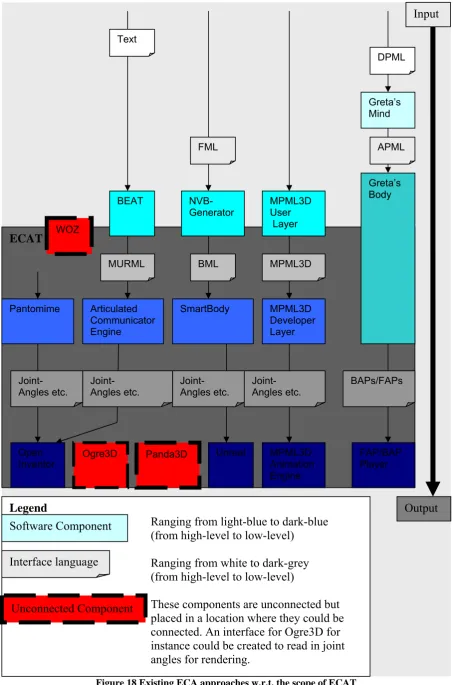
Figure 8 shows the scope of ECAT with relation to these both stages. Figure 18 on the end of this chapter is similar to Figure 9, with the difference that all the markup languages and systems discussed in section 2.2 and 2.3 are included into one schematic overview.
Figure 18 Existing ECA approaches w.r.t. the scope of ECAT ECAT
Legend
Ranging from light-blue to dark-blue (from high-level to low-level)
Ranging from white to dark-grey (from high-level to low-level)
These components are unconnected but placed in a location where they could be connected. An interface for Ogre3D for instance could be created to read in joint angles for rendering.
Inventor Ogre3D Panda3D Unreal FAP/BAP Player
3
The Embodied Conversational Agent Toolkit (ECAT)
The first chapter introduced the modularization approach used by the ECA Toolkit (ECAT), see Figure 7. In the second chapter related systems have been discussed to illustrate the scope of ECAT, see Figure 18.
The first section of this chapter will start with a discussion of situations where ECAT can be useful and in which situations it might not be useful. The second section will show the architecture of ECAT. The remaining sections will discuss the interface languages and the three different modules of ECAT. As has been stated in section 1.3, one important goal of ECAT is to create a repository of these three different modules to be shared among researchers. The next two chapters will focus on specific implementations of each of these modules. The discussion in this chapter will be more general, about the architecture and the tasks and goals of each of the modules of ECAT, without going into details how this could be implemented.
3.1 (Additional) Modularization
Researchers may choose to use ECAT (modules) because they would like to use a state-of-the-art behavior realization system, such as ACE or SmartBody, for their own ECA. On the other hand, some researchers may already have a state-of-the-art system. Therefore they may not be interested to use any of the functionality of ECAT. For instance a research lab which uses BML, SmartBody and Unreal for behavior realization may have little or no interest in using ACE which uses MURML as input and Open Inventor. The Unreal engine however requires a quite expensive license, which could justify changing from Unreal to a cheaper solution. Such as for instance: Open Inventor, Panda3D or Ogre3D. Another reason why people might not want to adapt to specific ECAT modules is that their own behavior realization approach makes it easier to tweak the low-level behaviors resulting from the high-level specifications. Finding their system easier to tweak oftentimes stems from the fact that they are more familiar with their own work, which makes it easier to make small changes to it. It could also be the case that their behavior realization approach is just ‘better than the rest’ or just ‘fine as it is’. But even in this case a researcher could benefit from a public repository to gain useful insight for future improvements.
By working towards common interface standards, sharing and combining each others work will get easier and more efficient. For example, if somebody working on facial expressions uses ECAT and someone working on hand gestures also uses ECAT, both researchers can benefit from each other by implementing and combining their behavioral models without having to tweak their agents. Another example would be when one wants to test the effects of the agent appearance on learning. With a modular separation one can forget about the details about gestures and the technicalities involved in the graphics engine.
Some of the previous examples are also possible when researchers use just the SAIBA framework and not ECAT per se. In fact, the SAIBA framework already has proposed two interface standards which can prove to be an important step towards common interface standards. However it takes time before a collection of compliant systems has been developed. In the future ECAT systems can be part of this collection, thereby helping to work towards common standards. Once standards are established and accepted by a large party, sharing each others work can become a reality.
level behavior to low-level specifications and the second part is responsible for rendering using these low-level specifications as input.
This separation gives new possibilities, for instance when trying out a CAVE setting, one could easily test multiple graphics engines to see which one works best. Also when moving from an expensive engine such as the Unreal engine, one could test low-cost different graphics engines before deciding to switch to a specific engine.
In general having a repository of alternative modules gives the possibility to benchmark modules, so more informed decisions can be made when choosing for a certain approach. It also allows researchers to focus on the research at hand because they do not have to focus on the complete system. The complete system can for a larger part be built from existing modules. With a repository of modules, conforming to interface standards, researchers can also more easily share their work with others.
3.2 Architecture Design
Up until section 3.1 questions like: why, where and when to use ECAT have been addressed. The remainder of this chapter will focus on the design of ECAT, the architecture, its comprised modules and what they serve for.
Figure 7, Figure 8 and Figure 18 all show ECAT and its scope. Figure 8 just shows the scope: partly overlapping behavior generation and completely overlapping behavior realization. Figure 18 is similar but shows a number of systems related to behavior generation and realization within this very same scope. Figure 7 shows the kind of input and output of the three modules of ECAT. Figure 19, which is shown below, can be seen as a combination of Figure 7, Figure 8 and Figure 18.
Figure 19 ECAT Architecture
While Figure 7 shows module 1, 2 and 3, Figure 19 shows the names: Interpreter, Compiler and Translator. These names will be used for the three different modules of ECAT. To keep the three realization modules platform- and language-independent, all inter-module communication is performed via a socket connection.
Within ECAT the three modules correspond to three stages: interpretation, compilation and finally translation. The first chapters of this thesis in combination with Figure 19 should
ECAT
WoZ Interpreter
MPML3D Interpreter Compiler(ACE)
Translator OpenInventor
Translator Panda3D
NUMACK Interpreter Translator Ogre3D
Behavior generation Behavior realization
High-level
behaviors in a
standard
format
Low-level
behaviors in a
standard
already give a good idea of the scope of ECAT and also the nature of the three stages. The upcoming subsections will discuss each of the stages in greater detail.
Before moving on to this discussion, it bears mentioning that ideally there is going to be a repository of modules for each of the different stages, as has been mentioned in section 1.3. The most complex work is carried out during compilation. The process of compilation is not connected to the ‘outside world’ but it’s encapsulated between interpretation and translation. Therefore it’s likely that the Compiler component (shown grey in both Figure 7 and Figure 19) can serve a multitude of ECA applications while both Interpreter(s) and Translator(s) are more tailored towards a specific implementation. For this reason an ideal repository of modules will only contain one or a few Compilers and a wide variety of Interpreters and Translators.
Before moving on to the design of the different stages, the interface data will be discussed, in Figure 7 and Figure 19 referred to as: ‘High-level behaviors in a standard format’ and as
‘Low-level behaviors in a standard format’. The nature of both high and low-level behaviors
has been previously discussed in section 1.3.
3.3 High-level behaviors in a standard format
The choice for the format to be used by ECAT for specifying high-level behaviors is largely motivated by the choice which system to use at the core of the Compiler6. Section 2.3
mentioned several candidate behavior realization systems. The Compiler used for the proof-of-concept version of ECAT uses the Articulated Communicator Engine (ACE) at its core. The implementation of this Compiler will be discussed in chapter 4.2. The motivation to choose for ACE will be described in chapter 3.5.2.
Since ACE, uses the Multimodal Utterance Representation Markup Language (MURML) as input; the input language for the Compiler will also be MURML. It is however important to note that efforts to add native support for the Behavior Markup Language are currently underway at the University of Bielefeld. This means that the Compiler will also support BML as input in the future. The fact that BML is going to be supported in the future was an important point in the decision to use ACE. Otherwise ECAT wouldn’t really be moving towards a common standard (SAIBA+BML) but rather moving away from it. Moving towards (and supporting) a common standard is key to the success of ECAT, as has been illustrated in section 3.1.
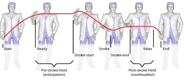
Figure 20 Gesture phases7
Because both MURML and BML will be supported in the future, both will be discussed in the following subsections. Both languages use gesture phrases as a mechanism of timing. Kendon
6 We are talking about ‘The Compiler’ here, although there can be more than one. Even if more Compilers are being
developed they should conform to the same interface standards.
[32] refers to the part where the gesture shows ‘peaking in effort’ as the ‘stroke’. This has since then been widely adopted. More specifically, McNeill [49] speaks of a gesture phrases consisting of the following phases: preparation, pre-stroke hold, stroke, post-stroke hold and retraction. Except for the stroke phase, all the phases are optional. Figure 20 shows an example gesture, with the different phases in it.
3.3.1 MURML
The Multimodal Utterance Representation Markup Language (MURML) [35,42] is the language natively supported by the Articulated Communicator Engine (ACE), in this sense it is used in ECAs like NUMACK [65] and Max [37]. The language allows speech and gesture to be specified along with cross-modal timing information.
According to Kranstedt, Kopp and Waschmuth [42] the communicative intent of a gesture can be sufficiently described in terms of the spatio-temporal features of its stroke. In the markup language they describe (MURML) this is exactly how a gesture can be described, namely using features of its stroke. Therefore MURML does not specify gestural behavior during preparation, hold and retraction phases.
Based on previous research, Kopp [35] states the following (which he refers to as segmentation hypothesis): “Continuous speech and gesture are co-produced in successive segments each expressing a single idea unit”. He also notes that speech is organized over intonation phrases, phrases which are separated by significant pauses. Chunks are defined as pairs of intonation phrases and a coexpressive gesture phrase. Inter- or intrachunk timing of paraverbal and nonverbal behaviors can be specified in terms of affiliate onset and end times. The affiliate of a behavior is the word or subphrase which is affiliated with the specific behavior.
<definition> <utterance>
<specification>
And now take <time id=“t1”/> this <time id=”t2”/> bar <time id=“t3”' chunkborder=“true”/> and make it <time id=“t4”/> this big. <time id=“t5”/>
</specification>
<focus onset=”t1” end=”t2” accent=”H*”/> <behaviorspec id=”gesture_1”>
<gesture id=”pointing_to”>
<affiliate onset=”t1” end=”t3”/>
<param name=”refloc” value=”$Loc-Bar_1”/> </gesture>
</behaviorspec>
<behaviorspec id=”gesture_2”> <gesture>
<affiliate onset=”t4” end=“t5”/>
<constraints>
<symmetrical dominant=”right_arm” symmetry=”SymMS”> <parallel>
<static slot="HandShape" value="BSflat (FBround all o) (ThCpart o)"/> <static slot="PalmOrientation" value="DirL"/>
<static slot="ExtFingerOrientation" value="DirA"/> <dynamic slot="HandLocation">
<dynamicElement type="linear">
<value type="start" name="LocShoulder LocCenterRight LocNorm"/> <value type="direction" name="DirR''/>
<value type="distance" name="125.0''/>
</dynamicElement>
The Figure above shows an example MURML specification which shows: a) Chunking of speech (chunkborder=”true”)
b) Gesture timing specified in terms of affiliate onset time.
c) Stroke of the gesture specified in terms of its spatio-temporal features.
Point a and b have been explained above, however point c needs some more explanation. Gestures in MURML can be defined (like in Figure 21), in terms of HandShape, PalmOrientation, Extended FingerOrientation and HandLocation which stem from HamNoSys [57], which is a notation system for German sign language.
Figure 22 The three body planes [35]
Each of the four components used for gesture definitions can be described numerically or symbolically (like in Table 4). The location of the hand can be described using three symbols referring to its position in each of the three body planes, which are shown in Figure 22. The three body planes: Frontal, Sagittal and Transversal shown in the figure correspond to planes commonly used in anatomy.
Symbol Value
HandLocation = LocFrontal LocTransversal LocSagittal
LocFrontal LocAboveHead, LocHead, LocForehead,
LocEyes,
LocNose, LocMouth, LocChin, LocLowerChin, LocNeck, LocShoulder, LocUpperChest,
LocLowerChest, LocStomach, LocBelowStomach,
LocHip, LocBelowHip
LocTransversal LocCCenter, LocBackof, LocCCenterRight,
``LocCCenterLeft, LocCenterRight. ``LocCenterLeft,
LocExtremePeripheryLeft, LocLeft, LocRight
LocSagittal LocContact, LocNear, LocNorm, LocFar,
LocStreched
Handshape = Basicsymbol [(Thumbsymbol)] Fingersymbol)
Basicsymbol BSfist, BSflat, BSffinger
Thumbsymbol ThExt, ThAcr, ThCpart [Degree]
Fingersymbol FBstr Finger, FBangle Finger [Degree], FBround Finger [Degree], FBroll Finger, FBbent Finger,
FBstiff Finger
Finger ll, p, m, r, l
Degree c, no, o, wo
ExtendedFingerOrientation = Direction PalmOrientation = Direction | RelativeRotation
Direction DirL, DirLU, DirLD, DirR, DirRU, DirRD, DirU,
DirD,
DirA, DirAL, DirAR, DirAU, DirAD, DirT, DirTL, DirTR
DirTU, DirTD
RelativeRotation PalmL, PalmLU, PalmLD, PalmR, PalmRU,
PalmRD,
PalmU, PalmD, PalmA, PalmAL, PalmAR, PalmT,
PalmTL, PalmTR, PalmAU, PalmAD, PalmTU, PalmTD
Table 4 Symbolic values which can be used for gesture descriptions in MURML [35]
In addition to the symbols used for describing the gestures Figure 21 also shows two types of ‘movement constraints’ (according to Kopp [35]), namely dynamic and static. A static constraint defines a posture which is to be held for a certain period, a dynamic constraint defines a movement. Figure 21 shows such a movement, which in this case describes a linear movement directed to the right and covering a distance of 125. In addition to linear movement, Kopp also defines curve shaped movement which has additional parameters describing the movement (see [35]). Additional tags like parallel and symmetrical can further describe the nature of the gesture (see [35] for a complete set of tags and their possible values). In this case gesture_2 describes a gesture which is symmetrical with respect to the sagittal plane and where the left hand mirrors (the dominant) right hand. The dynamic element species that the right hand should move 125 to the right, in this case the left hand would move 125 to the left, looking at the affiliate speech: “this big”, the gesture_2 describes the size which the bar is to be made (“…take this bar and make it this big”).
Specifying gestures using their overt form (like gesture_2) is a distinct feature of MURML, however gestures can also be specified using low-level keyframes or refer to a communicative function or a gesture from a gesticon. Being able to specify gestures using their overt form enables users to easily add new gestures. Normally adding new gestures would involve first creating an animation for the model using 3d software and second export this animation so it can be used from the gesticon.
The first gesture mentioned in Figure 21, uses an identifier (“pointing_to”) which can be used by the system to look up the gesture in the gesticon. Gestures of this sort can be parameterized to maintain a certain sense of flexibility. Gesture_1 for instance uses a parameter called ref_loc which makes the gesture point to the desired location.
3.3.2 BML
The inchoate Behavior Markup Language (BML) which can be seen as successor of (among others) MURML, is a growing and still evolving language. BML was formed as one of the interface languages of the Social Performance framework [46] which led to the more recent SAIBA framework [38]. Since the beginning of the SAIBA framework more and more research projects has began using BML. One of these projects involves the Articulated Communicator Engine (ACE) which, as stated before, is the core component of the ECAT-Compiler (see 4.2). On going work at the University of Bielefeld is focused on making the ACE system BML compliant. The current version which is used for ECAT is however not supporting BML, for now this means the ECAT-Compiler expects its input to marked up in MURML. In the future this could also be BML. For now developers of BML-compliant systems have to develop their own interpreter which can convert their (subset of) BML behaviors into corresponding MURML utterances.
Since the future support of BML in ACE (and therefore ECAT) was one of the factors driving the decision to use ACE as core component of the ECAT-Compiler, a brief discussion of the Behavior Markup Language will be given here.
Figure 23 Core BML which’s elements can be extended or new elements can be added. [69]
Recent developments [69] have added levels of descriptions to the originally proposed [38] Behavior Markup Language. BML now has a core level of description (level 0) and supports extension with higher levels of description (see Figure 23). In the SAIBA framework, BML interfaces between behavior planning and behavior realization (see Figure 1). Core BML defines a number of behavior elements8: speech, gesture, gaze, head, body, torso, face, legs,
lips and wait. The core level allows high-level descriptions for each of these elements. Additional descriptions levels can add more fine-grained behavior specifications for these elements. When additional elements might be needed in a behavior specification, these can be added by using a tag specifying a namespace corresponding to the name of the system which is expanding the core level. (For instance the CADIA system which defines a behavior called operate, see Figure 23 and Figure 24).
<bml>
<speech id=”s1” type=”application/ssml+xml”>
<text>This is an <mark name=”wb3”> example</text> </speech>
<head id=”h1” type=”NOD” stroke=”s1:start”/>
<gesture id=”g1” stroke=”s1:wb3” relax=”s1:end” type=”BEAT”> <description level=”1” type=”MURML”>...
</description> </gesture>
<gaze id=”z1” target=”PERSON1” stroke=”g1:stroke-0.1”/>
![Figure 9 Architecture of the MPML3D framework [51]](https://thumb-us.123doks.com/thumbv2/123dok_us/1030986.1128295/18.595.74.524.231.439/figure-architecture-mpml-d-framework.webp)
![Figure 11 Architecture of Behavior Expression Animation Toolkit (BEAT) [16]](https://thumb-us.123doks.com/thumbv2/123dok_us/1030986.1128295/19.595.74.475.515.713/figure-architecture-behavior-expression-animation-toolkit-beat.webp)
![Figure 12 Architecture of the NVBGenerator [44]](https://thumb-us.123doks.com/thumbv2/123dok_us/1030986.1128295/20.595.91.502.181.359/figure-architecture-of-the-nvbgenerator.webp)
![Figure 15 High and Low level commands in Pantomime [17]](https://thumb-us.123doks.com/thumbv2/123dok_us/1030986.1128295/21.595.79.523.334.469/figure-high-low-level-commands-pantomime.webp)
![Figure 16 Rapport Agent architecture, using Smartbody for behavior realization [22]](https://thumb-us.123doks.com/thumbv2/123dok_us/1030986.1128295/22.595.82.523.405.650/figure-rapport-agent-architecture-using-smartbody-behavior-realization.webp)
![Figure 17 Gesture Engine architecture, used in the Greta agent [26]](https://thumb-us.123doks.com/thumbv2/123dok_us/1030986.1128295/23.595.75.523.294.522/figure-gesture-engine-architecture-used-greta-agent.webp)