Direct Digital Frequency Synthesizer Based
On CORDIC Algorithm
Noble G
M.Tech, VIT University, Tamil Nadu, India
ABSTRACT: Direct Digital frequency synthesizer (DDFS) is a signal generation method and an essential part for local
oscillators, mixers and modulators. This paper will introduce a DDFS architecture which is based on the scale free micro-rotation CORDIC algorithm and its hardware realization is comparing with the pipelined CORDIC based DDFS. The frequency of the waveforms can be varied depending upon the applications. The design involves only shifting and addition/subtraction operations and hence the complexity is reduced. The rotational mode operation of the CORDIC algorithm is used for computing sine and cosine values.
KEYWORDS: Angle rotator, CORDIC algorithm,Direct Digital Frequency Synthesizer, Pipelined Architecture
I. INTRODUCTION
Direct Digital Frequency synthesis is one of the most recently developed frequency synthesis technique. It is possible to realize a DDFS in different ways. Most methods are using a look up table based approach [1]. That means, the sine and cosine values will be pre-calculated and stored it in the memory. This requires only less logic computations but needed a large memory. DDFS using CORDIC (COordinate Rotational Digital Computer) architecture can be implemented to overcome this problem. Here the sine values are computed using CORDIC algorithm.
The CORDIC algorithm uses only two operations for its functioning: addition/subtraction and shifting. It is possible to realize all mathematical functions like multiplication, division, exponential, trigonometric etc by using this algorithm. Since CORDIC is a repetitive algorithm, DDFS using CORDIC architecture can be implemented.
A frequency control word (FCW) is used for controlling the frequency in DDFS. It is an input parameter and it will be incremented by itself till an overflow is encountered. This section is called the phase accumulator. During an overflow, the phase value is given to the cordic processor and it will calculate the corresponding sine value. This sine value is passed through a digital to analog converter and a low pass filter in order to get the required sine waveform.
The remaining portion of this paper is discussed as follows. Section II will cover basics of CORDIC theory along with equations. Section III contains pipelined CORDIC architecture and its advantages. Section IV
reviews the micro-rotation based cordic architecture and section V will discuss DDFS based on the previous two algorithms. Section VI will compare all the realized structures and section VII concludes the paper.
II. CORDIC THEORY[LITERATURE SURVEY]
CORDIC theory was introduced by Volder [2] in 1959. Because of the simplicity of the algorithm, it has got a wide spread acceptance and now a days it is commonly used for the calculation of mathematical functions. It is a rotation based algorithm. That means an initial vector (Xo,Yo) is chosen and is subjected to rotation.
In this paper, rotational mode is described. That means, the initial vector (Xo,Yo) will rotates n times and hence obtain Xn and Yn [5].
Xn = Xocos Ɵ - Yo sine Ɵ
Yn = Xo sine Ɵ + Yocos Ɵ
In general, it can written as
Xi+1 =Xicos Ɵ i+1-Yisine Ɵ i+i
Yi+I=Xisine Ɵ i+1+ Yicos Ɵ i+i
The above equation contains four multiplications and two additions. Hence it is not feasible to use directly in the system. To make it more simple, we take the cosƟ term outside.
Xi+l= cos Ɵi+1 (Xi - Yitan Ɵi+1)
Yi+l= cos Ɵi+1 (Yi + Xitan Ɵi+1)
The term cosƟ is independent of iterations and having a constant value of 0.60725. In order to convert the multiplication of tan Ɵ to addition, the term tanƟ is restricted to ± 2-i.So multiplication can be replaced with arithmetic right shift.
Xi +1 =Ki (Xi - Yi2-i)
Yi+l= Ki (Yi + Xi2-i)
CORDIC is not a unidirectional rotational algorithm. For obtaining the desired angle, it is possible to rotate in both clockwise and anticlockwise directions [6]. Hence requires an extra variable to represent the direction of rotation and variable ‘d’ is included for that. Variable ‘d’ can be either positive or negative.
Xi +1= Ki (Xi - Yidi2-i)
Yi+l= Ki (Yi + Xidi2-i)
The value of d is decided by the rotation angle. Let us consider the rotation for an angle of 15 degree. It requires an initial rotation of 45 degree (pre-calculated) in anti-clockwise direction and then will calculate the difference. Thus a negative value is obtained and the next iteration will be a clockwise one. For this the variable Z is introduced.
Zi+1 = Zi- di Ɵ
Where Ɵ = tan-1(2-i).
III. PIPELINED CORDIC ARCHITECTURE
Because of the iterative behavior of the CORDIC, we can easily implement the algorithm in a pipelined architecture [7]. The basic block diagram of the pipelined CORDIC is shown in Figure 1.
Each stage consists of a CORDIC rotator along with a fixed angle for the rotation. The given input vector is rotated by the angle, which is stored in the ROM and is given to the input of the next stage. The vector is rotated further in each stage and finally will reach the exact angle that needed.
Fig.1. Pipelined CORDIC Architecture
This architecture has a scaling factor and angles required for iteration needs to be stored initially. Scaling free micro rotation based CORDIC can be used to avoid these problems.
IV. SCALING FREE-MICRO ROTATION CORDIC ARCHITECTURE
This algorithm is a modified form of the basic CORDIC algorithm with rotation angles limited to either clockwise or anticlockwise direction. Here the concept of Taylor series along with a generalized micro rotation concept is combined together [8][9]. The Taylor series expansion of the sine and cosine terms will avoid the scaling operation that is required in previous algorithm and provide a good range of convergence.
In this algorithm, the maximum rotation angle is limited to 45 degree. But by using the octant symmetry of the trigonometric functions, it is possible to extend the results into 360 degree.
The cordic function can be represented by using Taylor series as
Xi+1 = ( 1 -Ɵi22-1 )Xi–( Ɵi-Ɵi32-3)Yi
Yi+l=(Ɵi–Ɵi32-3)Xi + ( 1 –Ɵi22-1)Yi
Assign Ɵi=2-i
Xi+1 = [Xi - Xi-(2i+1)] - [Yi2-i – Yi2-(3i+3)]
Yi+l= [Xi2-i – Xi 2-(3i+3)] + [Yi – Yi2-(2i+1)]
Block diagram of the above CORDIC can be represented as in figure 3.
Fig.3.Cordinate Calculation
Rotations of this algorithm consist of two sections: basic shift and micro-rotation. Algorithm will perform multiple basic shift (n1 times) initially and then do unidirectional micro-rotations(n2 times). The total rotation angle is the sum of basic shift and micro-rotations (n1+n2).
The micro-rotation is identified from the bit representation of the required angle using most significant -1 detector. The algorithm which performs the micro-rotation is given below.
IV. a. Algorithm for Micro-rotation
Step 1: Let Ɵi be the angle to be rotated
Step 4: Micro rotation=0.25 radian, shift=2 and Ɵi+1=Ɵi-0.25
Step 5: Shift = Data width – M, Ɵi+1=Ɵi with Ɵi(M)= 0.
Step 6: Repeat Step 2 to Step 5 till Ɵi=0.
The scaling free cordic architecture consists of three stages: One for generating shift values, second one for generating the micro-rotations and finally a cordic calculation circuit. Fig. 3 shows the simulation results obtained from ModelSim.
Fig.4.Scale free micro rotation cordic simulation waveforms
V. DIRECT DIGITAL FREQUENCY SYNTHESIZER
DDFS is a technique used for generating sine and cosine values. It is different from traditional wave generators[10].Normal DDFS consists of a ROM Look-up table which will contain the sine and cosine values of all the phases. But the usage of large ROM’s inside the DDFS will reduce the performance of the system and raise the consumption of power. So a scaling free micro-rotation CORDIC based DDFS architecture, which does not require any Look-up tables, is proposed here.
In the proposed method the sine wave generator is replaced with scaling free CORDIC architecture. That means the sine and cosine values are calculating only by using addition and shifting operations.
Fig.4. DDFS Architecture
Phase accumulator is basically an adder, which will increment by itself in terms of FCW till an overflow condition is reached. When an overflow is occurred in the accumulator, the phase value will be given to the CORDIC section, which is developed based on the previously discussed Scaling free micro-rotation based CORDIC algorithm. It will provide the sine and cosine values of the given phase angle and this value is given to the Digital to Analog Converter (DAC).
Because of the usage of the efficient CORDIC algorithm in the DDFS architecture, it is possible to achieve higher performance with lesser hardware requirements.
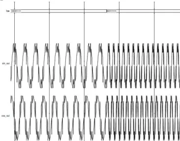
Fig.5. DDFS using scale free micro-rotation based CORDIC
VI. COMPARISON AND DISCUSSION
The Direct Digital frequency Synthesizers using pipelined CORDIC architecture and scaling free CORDIC architecture is implemented using Verilog HDL.Both architectures are simulated using ModelSimand synthesized using Xilinx ISE. The synthesis results obtained from Xilinx ISE for Spartan 3E series FPGA XC 3s250e is shown in table I.
TABLE I
Number of Slices
Slice Flip Flops
4 input LUTs
Bonded IOBs
Max.Freq. MHz
Slice Delay Product Pipelined
CORDIC DDFS
547 237 1055 38 58.54 4.04
Proposed DDFS
355 160 624 25 52.28 3.06
VII. CONCLUSION
This paper presents an efficient hardware implementation for DDFS with good numerical properties. Compared with the previous one,the proposed DDFS is ROM-less and consumes less area. Due to its highperformance and less area, it meets the needs of signal generation, local oscillators, mixers and modulators in engineering systems.We can further improve our design by using differential cordic algorithm [11] or higher radix cordic algorithm [12].
REFERENCES
1. Weibo Hu, Chung Len Leeand Xin’an Wang
”
Arbitrary Waveform Generator Based on Direct Digital Frequency Synthesizer” 4th IEEE
International Symposium on Electronic Design, Test &Applications,vol. 2 pp.567-570, 2008
2. J. E. Volder, “The CORDIC trigonometric computing technique,” IRE Trans. Electron. Computers, vol. EC-8, pp. 330–334, Sept. 1959. 3. KoushikMaharatna, Swapna Banerjee, Eckhard Grass, Milos Krstic, and Alfonso Troya,” Modified Virtually Scaling-Free Adaptive CORDIC
Rotator Algorithm and Architecture” IEEE Transactions on Circuits and Systems for Video Technology, vol. 15, NO. 11, NOVEMBER 2005. 4. P. K. Meher, J. Valls, T. B. Juang, K. Sridharan and K. Maharatna,“50 Years of CORDIC: Algorithms, Architectures, and Applications,”IEEE
Transactions on Circuits and Systems—I: Regular Papers, Vol.56(9),pp.1893-1907, Sept. 2009.
5. Ray Andraka “A survey of CORDIC Algorithms for FPGA based Computer” ACM 1998.
6. M. Chakraborty, A. S. Dhar and Moon Ho Lee, “A Trigonometric Formulation of the LMS Algorithm for Realisation of Pipelined CORDIC,”
IEEE Trans. Circuits and Systems, vol. 52, no. 9, pp. 530- 534, Sep.2005.
7. E. O. Garcia, R. Cumplido and Miguel Arias, “Pipelined CORDIC Design on FPGA for a Digital Sine and Cosine Waves Generator,”2006 3rd
International Conference on Electrical and Electronics Engineering(ICEEE),pp.104-107, Sept.2006
8. SupriyaAggarwal, Pramod K. Meher, and KavitaKhare “Area-Time Efficient Scaling-Free CORDIC Using Generalized Micro-Rotation Selection” IEEE Transactions on Very Large Scale Integration (VLSI) Systems, vol. 20, no. 8, august 2012
9. D. Fu and A. N. Willson, Jr., “A two-stage angle-rotation architecture and its error analysis for efficient digital mixer implementation,”
IEEETrans.Circuits Syst. I: Reg. Papers, vol. 53, no. 3, pp. 604–614, Mar. 2006.
10. Martin Kumm, HaraldKlingbeil, and Peter Zipf “An FPGA-Based Linear All-Digital Phase-Locked Loop” IEEE TRANSACTIONS ON
CIRCUITS AND SYSTEMS—I: Regular Papers, vol. 57, no. 9, September 2010
11. C. Y. Kang and E. E. Swartzlander, Jr., “Digit-pipelined direct digital frequency synthesis based on differential CORDIC,” IEEE Trans.
CircuitsSyst. I, Reg. Papers, vol. 53, no. 5, pp. 1035–1044, May 2006.
![The quality of ‘egusi’ melon [(Citrullus lanatus Thunb.) Matsum and Nakai] seeds derived from fruits harvested at different growth stages and at different positions on the mother plant](data:image/gif;base64,R0lGODlhAQABAIAAAP///wAAACH5BAEAAAAALAAAAAABAAEAAAICRAEAOw==)