Sensorless Control of BLDC Motor Using
Back EMF Method
Vinayaka K U 1, Priya S 2
Asst. Professor, Department of EEE, SIT, Tumkur, India.
PG Student, Department of EEE, SIT, Tumkur, India.
ABSTRACT: Brushless dc motors and the modelled drives are working and moving faster in the market. BLDC drives are patterned with six-step commutation with commutation controlled using position sensors. Sensorless drives are preferred to minimize complexity and cost of the system. Here, direct detection of back EMF, is presented for sensorless BLDC drives. For this method, no need of measuring motor neutral voltage in order to measure the back EMF. The off period of PWM detects the floating motor windings true back emf. Because, motor terminal voltage is proportional directly to phase of back EMF in this interval.
This theory presents the back EMF control method.
I. INTRODUCTION
Brushless DC Motor works with electronic commutation method to supplement the electro-brush in DC drives. It reduces the disadvantages of DC motor, like brushed commutation. Because of the advantages of brushless drives such as wide range of speed, good mechanical linearity characteristic, long life service, easy maintain, high and good reliability, less noise, no spark during commutation etc, this drives are extensively used in household and electrical appliances, automotive industrial equipment, and military equipment is applied in different field on the brushless DC drives control. Presently, brushless DC drive development is moving intelligent, digital, position sensors and direction control.
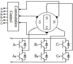
II. PRINCIPLE OF BRUSHLESS DC MOTOR
Brushless DC motor by motor ontology, location, signal detecting device and electronic reversing switch circuit ( inverter ) consists of three parts. It’s principle structure as shown in Figure 1.
Fig 1: Principle diagram of brushless DC motor
field direction, ensure appropriate torque angle, driven rotor spinning. Stator flux of movement is stepping and changes its frequency depending on the motor speed.
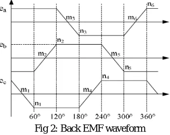
III. BACK - EMF METHOD
Rotor position detection of signals is a Brushless DC motor without position sensor control and key. In recent years, both at home and abroad where there have been many signal detection method. " Back - EMF method " is by far the most mature, the most effective and the most widely used method of rotor position detection. It also includes three main methods : zero - crossing method, phase - lock loop method and integration method. Back electromotive force method usually refers to the zero - crossing method.
Fig 2: Back EMF waveform
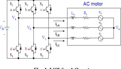
IV. SPACE VECTOR PULSE WIDTH MODULATED CONTROL
Space vector pulse width modulating strategy is an innovative method which provides an efficient feature. Hence, this method is chosen as best of all PWM methods for the application of variable supply frequency drives. It has excellent performance characteristics; hence extends the applications in inverter drives with reduced harmonics[4].
V. MERITS OF SPACE VECTOR METHOD
It provides good fundamental inverter voltage.
Spectrum of harmonics is improved.
It is easy to implement in digital controllers like microcontrollers and DSPIC processers.
Fig 3: Resultant space vector and 3ϕ voltage
The sum of 3 vectors is 0 for balance supply system. So, it is represented as single reference space vector( ). The
voltage and frequency of a motor is controlled by controlling frequency and amplitude of . Space vector modulation
controlled voltage source inverter is shown in the below figure 4.
Fig 4: VSI for AC motor
To operate the inverter drive in safe mode, in each leg only one switch should conduct at a time. When Q1 is in conduction Q2 must be in reverse bias condition and vice versa. In SVPWM method 8 states of switching is provided.
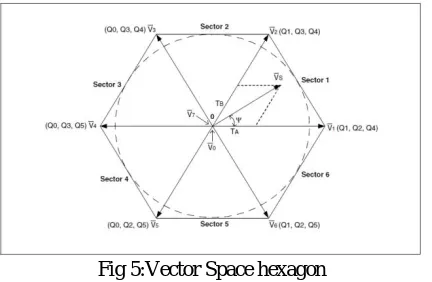
The switching patterns from 1-6 are active states, where motor gets energized from the supply. Remaining two states are inactive states as energy is not supplied. The below figure shows representation of switching in space vector[5].
Fig 5:Vector Space hexagon
In this figure the hexagon is split to 6 sectors of Two active vectors bounds each sector. Two inactive states are
vectors with amplitude zero and starts in the origin of hexagon. Since this method has high amplitude of line-line voltage, motor generates high torque and improves the dynamic response[6]. Due to the sequential switching of inverter, the resultant is . The switching frequency of inverter circuit is high enough to avoid the audible noise during switching.
VI. SIMULATIONS AND RESULTS
The simulation of sensorless control of BLDC motor is shown below,
Back emf current
VII. CONCLUSION
Experimental results show that detection of back electromotive force projections of zero - crossing points and thus the rotor position is accurate and reliable, to correct commutation of brushless DC motor operation. Sensorless control of this technology is practical and effective, study on Sensorless control system is of important practical significance and broad development prospects.
REFERENCES
1. Yongliang Liu, Yuanlou Gao, “Research of Sensorless controller of BLDC Motor” , Beijing: Science Press, 2014. 2. B. K. Bose, “Power Electronics and Variable Frequency Drives: 39 Technology and Applications.”IEEE Press, 1997.
3. R. Krishnan, “Electric Motor Drives Modelling, Analysis and Control”, Prentice Hall, 2001.
4. Prof. B. Chitti Babu “Control of Voltage Source Inverters using PWM/SVPWM for Adjustable Speed Drive Applications”,NIT, Rourkela, May 2009
5. Devisree Sasi1, Jisha Kuruvilla, “Modelling and simulation of SVPWM invereter fed permanent magnet brushless DC motor” Mar Athanasius College of Engineering, Kerala, India.
6. Yi Huang, Chunquan Li “Model and system simulation of Brushless DC motor based on SVPWM control” 2nd International Conference on