WIRELESS LOCAL AREA NETWORK BASED
INDOOR POSITIONING SYSTEM
By
KEOH CHOO KENT
A Dissertation submitted for partial fulfilment of the
requirement for the degree of Master of Science
(Microelectronic Engineering)
i
Acknowledgement
First of all, I would like to take this opportunity to thank those people who had helped and supported me in the completion of this research.
I would like to express my deepest gratitude to my research project supervisor, Dr. Mohd. Tafir Bin Mustaffa for this precious ideas, support, patience and encouragement throughout the completion of this research. Besides that, he also share a lot of knowledge and useful advice that allow me to complete the development of the research in a much efficient and productive way.
Besides that, I would like to thanks my PSDC supervisor, Mr. Tony Lim for giving me the permission to use PSDC network infrastructure to do my research and implement the Indoor Positioning System in the campus area.
In addition, I would also like to express my gratitude to my family, especially my parents who provided me full support during development of my project. My family had given me a lot of encouragement, support and tried their best to help me when I was facing problem.
Last but not least, I would like to express grateful thanks and appreciation to all my friends and course mates for the support and ideas on solving the problem I faced during the development of the project.
ii
Table of Contents
Acknowledgement ... i Table of Contents ... ii List of Tables ... iv List of Figures ... vList of Abbreviations and Nomenclature ... vii
Abstrak ... viii
Abstract ... ix
PROJECT OVERVIEW ... 1
1.1. Introduction... 1
1.2. Problem Statement ... 2
1.3. Aims and objectives ... 2
1.4. Scopes of Research ... 3 1.5. Research Contribution ... 4 1.6. Thesis Organization ... 4 LITERATURE REVIEW ... 5 2.1. Introduction... 5 2.2. Positioning System ... 5
2.3. Outdoor Positioning System ... 7
2.3.1. Global Positioning System (GPS) ... 7
2.4. Indoor Positioning Technology ... 10
2.4.1. Bluetooth-based Positioning System ... 10
2.4.2. RFID-Sensor-Based Indoor Positioning System ... 13
2.4.3. WLAN based Positioning System ... 17
2.4.3.1. Type of Wireless LAN ... 17
2.4.3.2. IEEE 802.11 Standards ... 18
2.4.3.3. WLAN positioning concept... 19
2.5. Comparison of Positioning Technologies ... 22
2.6. Indoor positioning Method and parameter ... 24
2.6.1. Received Signal Strength (RSS) Location Fingerprint ... 24
2.6.2. Time of Arrival for Trilateration ... 26
2.6.3. Angle of Arrival ... 28
2.6.4. Comparison of the Indoor Positioning Methods with Parameters ... 29
iii
DESIGN METHODOLOGY ... 31
3.1. Project Flow Chart ... 31
3.1.1. Design Flow Chart ... 31
3.2. Project overview ... 33
3.2.1. Received Signal Strength from Access Point ... 34
3.2.2. WLAN Positioning Module ... 35
3.2.3. Predefined Location... 37
3.2.4. Software Programming flow chart for RSS behavior test ... 38
3.2.5. Software Programming flow chart for the Positioning System ... 41
3.2.6. Predefined Location Mapping ... 45
3.3. Overall System ... 49
3.4. Summary ... 52
EXPERIMENT, ANALYSIS, RESULT AND DISCUSSION ... 53
4.1. Introduction... 53
4.2. Effect of Distance with different type of Routers ... 54
4.3. Effect of wall obstacle ... 56
4.4. Effect of temperature ... 58
4.5. Effect of different model of router ... 60
4.6. Effect of interference ... 63
4.7. Summary from the experiment ... 66
4.8. WLAN indoor positioning with two Access Points ... 67
4.9. WLAN Indoor Positioning with three Access Points. ... 69
4.10. Signal Coverage Analysis ... 71
4.11. Overall system test at selected point ... 73
4.12. Overall system accuracy test ... 75
4.13. Chapter Summary ... 78 CONCLUSION ... 79 5.1. Conclusion ... 79 5.2. Future Development ... 80 REFERENCES ... 81 APPENDIX A ... 85 APPENDIX B ... 96 APPENDIX C ... 100
iv
List of Tables
Table 2.1 GPS Frequency Usage and Application[4], [5], [6] ... 8
Table 2.2 Comparison of GPS improvement Techniques ... 10
Table 2.3 Bluetooth classes with the effective range [11] ... 11
Table 2.4 Data rate of each Bluetooth Version ... 11
Table 2.5 Comparison of Bluetooth positioning techniques ... 13
Table 2.6 Type of RFID tag [18] [19] ... 15
Table 2.7 Comparison of RFID positioning techniques ... 16
Table 2.8 Types of IEEE 802.11 Standards ... 18
Table 2.9 Comparison of IEEE 802.11 Standards ... 19
Table 2.10 Comparison of WLAN positioning technique ... 21
Table 2.11 Comparison of Positioning Technologies ... 22
Table 2.12 Comparison of Indoor Positioning Methods with parameters ... 30
Table 3.1 The coordinate used in MATLAB to mark the location of the user/object ... 47
Table 4.1 Results of the RSS value versus the distance ... 55
Table 4.2 Result for the RSS pass through multiple walls ... 57
Table 4.3 Result of the RSS value with different temperature ... 59
Table 4.4 Specification of different router ... 61
Table 4.5 The Result of of RSS value from different model of routers ... 62
Table 4.6 The result of the RSS value without interference (from Chapter 4.4) ... 63
Table 4.7 The result of the RSS value with interference ... 64
Table 4.8 The result of data collection for the 12 points ... 67
Table 4.9 The Maximum and minimum range of RSS value ... 68
Table 4.10 The result of RSS value from three routers ... 70
Table 4.11 The maximum and minimum range for the RSS value from three routers ... 70
Table 4.12 Experiment result at Point 1 ... 76
Table 4.13 Experiment result at Point 3 ... 76
v
List of Figures
Figure 2.1 Types of Positioning System ... 7
Figure 2.2 Space Vehicle surrounding the Earth [3] ... 8
Figure 2.3 The location of Access Point placed ... 12
Figure 2.4 Indoor Positioning System with camera and RFID ... 16
Figure 2.5 WLAN Indoor Positioning Technique ... 20
Figure 2.6 Fingerprint parameter in a sample space [34] ... 25
Figure 2.7 Time of Arrival method ... 27
Figure 2.8 Angle of Arrival method ... 28
Figure 3.1 Design Flow Chart ... 31
Figure 3.2 Selected 12 points for RSS value collection ... 33
Figure 3.3 Overall project block diagram ... 33
Figure 3.4 Overall WLAN positioning module ... 35
Figure 3.5 Predefined Space (Block 3 Level 2) ... 37
Figure 3.6 Software Programming Flow Chart for RSS behavior test ... 38
Figure 3.7 Source code for initialize the Arduino Wi-Fi Shield CC3000 ... 39
Figure 3.8 Predefined SSID for 3 access point... 39
Figure 3.9 Source code for collect RSS from respective SSID ... 40
Figure 3.10 Software Programming flow chart for the Positioning System (Part 1) ... 41
Figure 3.11 Software Programming flow chart for the Positioning System (Part 2) ... 42
Figure 3.12 Software Programming flow chart for the Positioning System (Part 3) ... 43
Figure 3.13 Source code for I2C ... 44
Figure 3.14 The predefined lookup table in Arduino IDE ... 45
Figure 3.15 The sample of 12 point show by MATLAB ... 46
Figure 3.16 Source in MATLAB to locate the location and plot in the GUI ... 47
Figure 3.17 Sample GUI in MATLAB ... 48
Figure 3.18 Overall System Block Diagram ... 49
Figure 3.19 The Overall System... 49
Figure 3.20 Ruckus ZenoFlex R500 [36] ... 51
Figure 4.1 Setup for the experiment on effect of distance against RSS value ... 54
Figure 4.2 The graph of the RSS value against the distance ... 55
vi
Figure 4.4 The graph of the RSS value pass through multiple walls against the distance ... 57
Figure 4.5 Three different temperature when the RSS is captured ... 58
Figure 4.6 The graph of RSS value against temperature (1m) ... 59
Figure 4.7 The graph of RSS value against temperature (2m) ... 59
Figure 4.8 The graph of RSS value against temperature (3m) ... 60
Figure 4.9 The setup for the experiment to measure RSS value from different routers ... 60
Figure 4.10 Different model of routers ... 61
Figure 4.11 The graph of RSS value captured by different model of router against the distance ... 62
Figure 4.12 The setup for the experiment to test the interference ... 63
Figure 4.13 The RSS value of the Ruckus router with and without interference ... 64
Figure 4.14 The RSS value of TM Unifi router with and without interference ... 64
Figure 4.15 The RSS value of Netgear router with and without interference ... 65
Figure 4.16 The configuration of the Ruckus rouet ... 65
Figure 4.17 The configuration of the Netgear router ... 66
Figure 4.18 The configuration of the TM Unifi router ... 66
Figure 4.19 The setup of two routers and the predefined 12 points ... 67
Figure 4.20 Problem occurred when only two router. ... 69
Figure 4.21 The location of the three routers ... 69
Figure 4.22 Ideal Signal Strength for each router ... 71
Figure 4.23 Critical place that signal barely can reach for AP 3 ... 72
Figure 4.24 The result of the experiment on the critical place ... 73
Figure 4.25 The Experiment at Point 1 ... 74
vii
List of Abbreviations and Nomenclature
Abbreviations Meaning
RSS Received Signal Strength
RSSI Received Signal Strength Indicator GUI Graphic User Interface
GPS Global Positioning System IPS Indoor Positioning System WLAN Wireless Local Area Network SSID Service Set Identifier
RFID Radio Frequency Identifier LOS Line of Sight
IEEE Institute of Electrical and Electronic Engineers
AP Access Point
SVs Space Vehicles
viii
SISTEM KEDUDUKAN DALAM PERSEKITARAN TERTUTUP
BERDASARKAN RANGKAIAN KAWASAN SETEMPAT TANPA
WAYAR
Abstrak
Kajian ini bertujuan untuk mengatasi kelemahan liputan Sistem Kedudukan Global dalam persekitaran tertutup. Sistem kedudukan ini dibina menggunakan rangakian kawasan setempat tanpa wayar (WLAN) berdasarkan ‘IEEE 802.11n Standard’. Sistem ini diwujudkan bertujuan untuk mengesan lokasi pengguna/objeck dengan persediaan yang minimum dan menghasilkan keputusan pengesanan yang jitu. Sistem ini dilaksanakan pada komputer riba untuk memaparkan ‘graphic user interface’ yang menunjukkan lokasi pengguna/objek di atas peta yang ditetapkan. Sistem kedudukan ini menggunakan konsep triangulasi dengan kaedah pengesanan cap jari untuk menentukan kedudukan pengguna/objek. Penyambungan ‘Arduino Wi-Fi Shield CC3000’ dan ‘Arduino Mega’ bertujuan untuk mengumpul kekuatan isyarat yang diterima dari router tertentu dalam ruang yang ditetapkan untuk menentukan lokasi pengguna/objek. Data yang dikumpul akan melalui satu algoritma kedudukan dan lokasi tersebut akan dihantar kepada ‘MATLAB’. Seterusnya, lokasi pengguna/objek akan dipaparan di ‘gaphic user interface’ yang telah diprogramkan di ‘MATLAB’. Untuk itu, kajian untuk mengenal pasti kekuatan isyarat yang diterima dari router telah dijalankan. Daripada eksperimen-eksperimen yang dijalakan telah berhasil mengenalpasti faktor-faktor yang berpotensi menpengaruhi prestasi sistem kedudukan. Selain itu, satu set pangkalan data untuk menilai kekuatan isyarat yang diterima dari router di 12 tempat yang ditetapkan telah dikumpul untuk mebina sistem kedudukan ini. Akhirnya, sistem kedudukan ini telah disahkan dan diuji dengan beberapa eksperimen untuk mengenalpasti dan menguji ketepatan serta kestabilan sistem ini. Sistem kedudukan ini dibina dengan prestasi yang halus dan memberikan ketepatan seratus peratus di bawah radius 2 m di sekitar tempat yang telah ditetapkan, 70% - 60% ketepatan dalam radius sekitar 2–3 m, 50% - 40% ketepatan dalam radius sekitar 3–4 m dan 30% - 20% ketepatan dalam radius sekitar 4–5 m. Ketepatan akan menurun apabila radius eksperimen diluaskan.
ix
WIRELESS LOCAL AREA NETWORK
BASED INDOOR POSITIONING SYSTEM
Abstract
This research is aimed to overcome the poor coverage of the Global Positioning System (GPS) in indoor environment. The indoor positioning system developed is based on the wireless local area network (WLAN) using the IEEE 802.11n standard. The positioning system is designed to self-locating of a user/object with the minimal setup of hardware and adequate accuracy. The system is implemented in a laptop to provide a visualized graphic user interface to shows the location of the user/object on the predefined map. The positioning system used the triangulation concept with the fingerprint method to locate the position of the user/object. An Arduino Wi-Fi Shield CC3000 is connected to an Arduino Mega is used to collect received signal strength (RSS) from individual wireless routers in predefined space to determine the location of the user/object. The data then will go through the predefined lookup table to locate the location of the user/object and the location will send to the MATLAB. The location of the user/object will then show in the graphic user interface in MATLAB. A set of experiment is conducted to identify the behavior of the RSS value toward the router. From the experiment, the potential factors that affect the performance of the positioning system is examined and identified. Besides that, a set of database of the RSS value on the predefined 12 points is collected to develop the lookup table. Lastly, the system is verified, validated and tested with a few experiments to test and determine the accuracy and stability of the system. The positioning system is developed with a fine performance and with a best accuracy of 100% at radius of less than 2m around the predefined point, accuracy of 70% - 60% at radius of 2 - 3 m radius, accuracy of 50% - 40% at 3 - 4 m radius and 30% - 20% at 4 - 5 m radius. When the area of the experiments around the predefined point increased the accuracy drop accordingly.
1
PROJECT OVERVIEW
1.1. Introduction
Nowadays, people are very relying on Global Positioning System (GPS) to locate a location or bring them to some places that are not familiar with. Besides that, GPS also has a drastic grow for the usages and applications such as navigator system or rescue system. However, the GPS requires on line of sigh to make sure that the signal transmits from the satellite is received effectively by the receiver. It works fine for outdoor positioning but the requirement seems not possible for the receiver to receive the signal in indoor environment as signal becomes weak when it enters indoor. Therefore, the indoor positioning is introduced to ensure the coverage of the positioning in indoor environment.
Indoor positioning evolved from the GPS that provide the positioning in an indoor environment. Indoor positioning is a new field of positioning that has rooms for improvement. It will be a new approach that is used to estimate or identify the location of the object in the indoor environment with the use of suitable technology and technique.
The development of such technology is to help human resolve the problem face in the daily life such as lost in location or direction in a complex indoor environment or loss of object in indoor environment. Hence, the project developments about indoor
2
positioning have been proposed to solve the problem of the positioning in indoor environment.
1.2. Problem Statement
Global Positioning System (GPS) is a very powerful system to locate the location of the user in outdoor environment. However, GPS requires line of sight in order to fully function. Therefore, GPS has faced some difficulties when there is no line of sight or the receiver of the GPS unable to receive the signal from the satellite. Furthermore, there has yet no proper positioning system being implemented for indoor environment. Besides that, there are few more problems as stated below:
People tend to loss of location and direction in a complex indoor environment.
The existing indoor positioning systems are commercial products and require extra setup of hardware and software.
The existing indoor positioning systems for individual are very time consuming process to identify the location and analyse the path to destination individually.
Lack of proper and generic solution to determine the location of each individual and provide indoor navigation to user.
1.3. Aims and objectives
The aim of the project is to research and study the existing positioning system and navigation technologies characteristics, thus propose a better solution for positioning system. The main focus of the system is to locate the location of user/object based on the Wireless Local Area Network (WLAN). Besides that, the system should
3
able to resolve the localization problem with better coverage. Therefore, the objectives are listed as following:
To analyse and identify an indoor environment with good coverage of WLAN.
To identify the behavior of the RSS values toward router.
To design and develop a simple installation and configuration system using the position estimation technique with a lookup table to identify the location of the user/object with an adequate accuracy, thus allow user to perform self-locating in indoor environment.
1.4. Scopes of Research
The research project scope will focus on providing a positioning system to locate the user/object in an indoor environment. Based on the literature review, the WLAN based indoor positioning system which utilizes the several of IEEE 802.11 is proposed as the performance and structure in this technology is suitable for a positioning solution in an indoor environment. This system is expected to be able to identify the location of the user/object in the predefined space.
The research of the project will start with experiment of the behavior of the RSS value toward the access point. Then, followed by design a system that have ability to gather the signal via wireless module and perform the positioning solution and thus identify the location of the user/object in the predefined indoor space.
4
1.5. Research Contribution
This project has significant contribution to technology of Indoor Positioning System. An embedded hardware with features of receiving RSS transmitted from the access point was designed. Besides that, a system is developed to process the RSS data and locate the location of the user/object.
1.6. Thesis Organization
The following chapters in the research project thesis will be organized as follows: Chapter 2 reviews the available outdoor and indoor positioning system, research about the strong point and weakness about each positioning technology and the advantages and disadvantages of the positioning techniques.
Chapter 3 describes the methodology of this research project. This chapter starts with the overall project flow and followed by the project overview of the system. Lastly end with the description of overall system.
Chapter 4 describes the experiment, result and discussion. First part of Chapter 4 includes the experiment, result and discussion of the behavior of RSS toward the access point. Then followed by the experiment, result and discussion on the system developed.
Chapter 5 explains and summarizes all the result and spell out future work for improvement.
5
LITERATURE REVIEW
2.1. Introduction
In order to develop the WLAN based Indoor Positioning System, many researches had been done to ensure that the information and the flow to develop the project are correct and the process of the development can be done smoothly. A positioning system uses a certain positioning algorithm to identify and locate the object or person. There is a lot of positioning technique but most recent techniques are developed based on the wireless technology. However, this technology is still unable to reach 100% accuracy but it is still reliable with a small amount of difference between the displacements of the position.
2.2. Positioning System
Positioning system is a system which uses certain algorithm and certain hardware to identify the location of an object or a person. Most of the current positioning techniques in the industry locate the object based on the wireless technique that able to identify the relative position of the object. However, the relative position of the object might have some mismatch or tolerance with the actual position of the object. The positioning system is reliable with a small amount of displacements of the position. The positioning system can be divided into mainly few types such as Outdoor
6
positioning system which is the Global Positioning System (GPS) and indoor positioning system which uses the help of Wi-Fi, Bluetooth and etc.
GPS also known as Global Positioning System is introduced to public in year 2000. Before that, the GPS system was first developed by the U.S. Department of Defense in year 1960 for military purpose[1]. GPS is a technique which used satellite signals to estimate the location of the person. A GPS receiver used to calculate the position by precisely the timing of the signals sent by the selected four GPS satellites high above the Earth. Each of the satellite continually transmits message that included the time the message was transmitted and the position of the satellite when the message was transmitted. The receiver then used the messages it received to determine the transit time of each message and calculate the distance between the satellites. Each of these distances and satellites locations define a sphere, so the receiver is located at the point where the spheres intersect.
However, when it comes to indoor environment, GPS is unable to locate the person owing to the weak penetration of satellite signals onto concrete walls. Therefore, several techniques without GPS are proposed recently such as Indoor Positioning System (IPS). IPS is a solution based on the sensor data or network of devices used to wirelessly locate an object or people inside a room. Network devices such as Access Point or router can be integrated with the technology of Wi-Fi to become an Indoor Positioning System. On the other hand, with the advance of integrated sensor technology, an indoor location is potentially to be estimated by using sensor such as Wi-Fi, accelerometer, gyroscope and magnetometer.
7
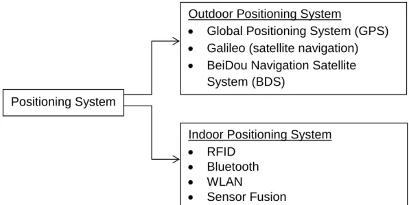
Figure 2.1 shows various types of the positioning system that can be used in the outdoor and indoor positioning system. The positioning systems can be widely used in a lot of applications, such as tracking system, navigation system, emergency rescue and etc.
2.3. Outdoor Positioning System
2.3.1. Global Positioning System (GPS)
Global Positioning System design originally is called as the “24 SVs” where there are total of 24 Space Vehicles (SV), or satellites are placed eight each in three approximately circular orbits, but this later was modified to six orbit planes with four satellites each[2]. As of February 2016, there are total 32 satellites in the GPS constellation. 31 of the 32 are in use to locate the location and the additional satellites use to improve the precision of GPS receiver calculations by providing redundant measurements. Figure 2.2 below shows the Space Vehicles surrounding the Earth.
Positioning System
Outdoor Positioning System
Global Positioning System (GPS)
Galileo (satellite navigation)
BeiDou Navigation Satellite
System (BDS)
Indoor Positioning System
RFID
Bluetooth
WLAN
Sensor Fusion
8
Figure 2.2 Space Vehicle surrounding the Earth [3]
The GPS is a robust technology that is able to work under any weather condition with the condition that the light of sight the receiver is provided. The GPS receiver which will pick up the signal information transmitted from the satellites of minimum four signals to determine the distance to each the time travelled by the signals. The signals then are used to locate the location or the position of the user on Earth by latitude and longitude and display it on the panel of the receiver. The technique used is based on the timing of arrival method that use the time of transmission and arrival to calculate the distance from the satellite and further calculate the position. The global positioning satellite transmitted a few frequencies for different application. The Table 2.1 shows the frequency bandwidth for each application:
Table 2.1 GPS Frequency Usage and Application[4], [5], [6] Band Frequency Application
L1 1575.42 MHz Coarse-acquisition (C/A) and encrypted precision P(Y)
codes, plus the L1 civilian (L1) and military (M) codes on future Block III satellites.
L2 1227.60 MHz L2 is for civilian use and there also two military signals in
L2 frequency. P(Y) code, plus the L2 and military codes on the Block IIR-M and newer satellites
L3 1381.05 MHz Used for nuclear detonation (NUDET) detection.
L4 1379.913 MHz Being studied for additional ionosphere correction
L5 1176.45 MHz Proposed for use as a civilian safety-of-life (SoL) signal.
L5 is broadcast in a radio band reserved exclusively for aviation safety services.
9
GPS is installed in most of the mobile devices in the market. However, there are a few limitations such as ionosphere and troposphere delay, signal multipath, receiver clock error, orbital error, visible satellite quantity, satellite shading, and also intention degradation of the signal is possible cause of the error receiving signal.
Besides that, GPS has an accuracy of 15 meters in outdoor. However, when come into indoor environment, GPS has a shortcoming on that. The main requirement of the GPS is the Line of Sight (LOS). When come into indoor environment, the signal reception and LOS of the GPS are blocked and lead to failure and inability of the system. Furthermore, the GPS signal is not strong enough to penetrate inside indoor environment as the signal reaches the receiver in indoor environment has attenuated and hard to recover. As the signal multipath occurs when the GPS signal is reflected off objects like wall, ceiling of building, terrains, electronic interference, or even dense foliage before reaches the receivers, thereby causing position errors or possibly no signal receive at all.
Thus, GPS is a very high accuracy positioning system. However, the GPS only can fully function when the receiver able to pick up the signal information from the satellites. Therefore, when come to indoor environment GPS lost it function and need the help of the Indoor Positioning System to locate the location of user/object.
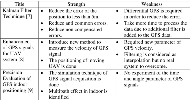
Table 2.2 shows the paper review on the GPS technology. From the paper review of GPS technology, it is shown that GPS has some room of improvement as there is still error and disadvantages on certain scenario. Besides that, there is also a technology which a filter is added into the GPS positioning system when the accuracy of the position does not reach the required level. The multipath effect of GPS is
10
identified with problems of Line of Sight of GPS receiver to the satellite. The GPS signal quality in indoor environment is shown poorly and not suitable for process.
Table 2.2 Comparison of GPS improvement Techniques
Title Strength Weakness
Kalman Filter Technique [7]
Reduce the error of the position to less than 5m.
Reduce anti common errors.
Reduce non compensated errors.
Differential GPS is required in order to reduce the error.
Take more time to process the data due to additional filter is added to the GPS data. Enhancement
of GPS signals for UAV system [8]
Introduce new method to measure the velocity of GPS signal
The positioning of moving UAV is done
Required new parameter of GPS velocity.
Filtering is considered as interpolation but no real system to overcome. Precision
Evaluation of GPS indoor positioning [9]
The simulation technique of GPS signal acquisition is done
Multipath effect in indoor is identified
No experiment of the time and angle parameter of GPS signals
2.4. Indoor Positioning Technology
2.4.1. Bluetooth-based Positioning System
Besides using Wi-Fi as the positioning tools, the Bluetooth device is also one of the tools that provide the positioning. Bluetooth is a wireless technology for exchanging data over a short distance. It is a short distance radio transmission that uses the ISM band from 2.4 to 2.485 GHz[10]. Bluetooth uses the Personal Area Network (PAN) that allows the communication between fixed devices with high level of security. The frequency hopping technique is used for the transmission of data with 79 designated Bluetooth channels which have 1 MHz bandwidth each[10]. Bluetooth uses a packet based protocol with master-slave structure where one master device can connect up to seven devices in a pico-net. Normally, Bluetooth allow the communication between
11
devices such as laptop, mobile devices, digital cameras and some compatible devices. Besides that, Bluetooth has a specific class for the transmission power to control the effective range shown in Table 2.3.
Table 2.3 Bluetooth classes with the effective range [11]
Class Permitted Power (mW) Permitted Power (dBm) Range (m)
Class 1 100 20 100
Class 2 2.5 4 10
Class 3 1 0 5
Class 4 0.5 -3 0.5
There are few factors that affect the coverage range of Bluetooth such as the antenna configuration, material coverage, battery condition, propagation condition and also the production sample variation[12]. Besides that, Bluetooth versions have been improved with the data transfer rate and feature. The Table 2.4 shows the different version of Bluetooth with the data transfer rate of each version.
Table 2.4 Data rate of each Bluetooth Version Version Data Rate (Mbits/s)
1.2 0.7
2.0 2.1
3.0 24
4.0 25
5 50
Although Bluetooth is a good wireless technology with good connection and private network, however, pairing connection for both devices needed to be done before any further application. Pairing connection is the process where both devices identify each other and give trust to each other. The pairing process creates a bond between two devices and gave trust to each other so that next time both devices are automatically
12
connect to each other without going through the process of pairing again. However, either one of the can remove the bonding between two devices in future.
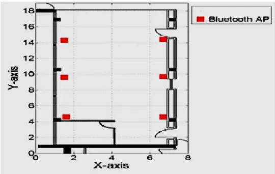
Using the same concept with the Wi-Fi-based Indoor Positioning System, the Bluetooth-based Indoor Positioning System also uses the RSS to locate the object or person. Ehad Akeila et al. setup six Bluetooth access points (AP) at different locations in a room as shown in Figure 2.3 [13]. Based on the location of individual Bluetooth AP, RSS from the neighbor APs were collected to form an approximation of the Friis model (an equation of converting the RSS value to distances using signal propagation model). After a unique Friis approximation model for each AP is formed, the positioning system chose the model with the nearest AP to the object. The final position of the object was obtained by firstly multiplying the probability density function (PDF) of all APs and then finding the location with the highest probability of the location.
13
Table 2.5 Comparison of Bluetooth positioning techniques
Title Strength Weakness
Positioning with Bluetooth [14]
Qualities that can be used to grade the positioning are introduced.
Direct and indirect method of positioning is used.
The maximum range of the Bluetooth transmission is limited to 10m.
Only single connection is allowed once at a time. Enhancing accuracy
performance of Bluetooth positioning [15]
The accuracy of the positioning has been improved to 1.5m.
Offset time acquisition is introduced.
The specification of the Bluetooth is modified to stress the accuracy of the positioning.
Bayesian Filtering for Bluetooth Positioning System [16]
Bayesian filtering steps is used with a good response.
Low period between measurements.
Dynamic human walking positioning is still a challenge.
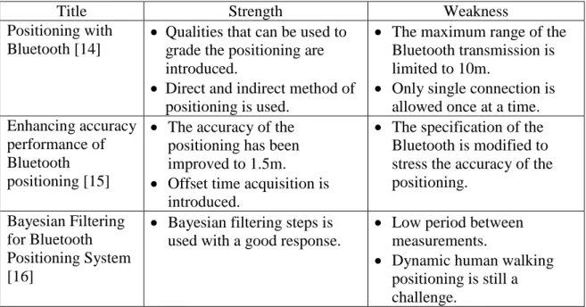
Table 2.5 shows the comparison of Bluetooth positioning technique from few papers. From the paper comparison, the Bluetooth positioning technique have a significant result where the positioning system able to locate the location of the user/object. However, there are some changing of few specifications of the Bluetooth standards or applying some filtering technique in order to able to locate the location of the user/object. The Bluetooth positioning system still has a big room to improve such as improving the coverage of the positioning system and optimized the time of connection.
2.4.2. RFID-Sensor-Based Indoor Positioning System
The sensor technology enables the sensors such as RFID, IR sensor, CMOS sensor-based camera with image processing, accelerometer, magnetometer and gyroscope to be used as the tools of Indoor Positioning System. Radio Frequency Identification (RFID) is a generic term that is used to describe a system that transmits
14
the identity (a unique serial number which tag on an object or person) wirelessly using radio waves [17]. A basic RFID system is used to identify the unique object, processes, transaction or events by using radio waves to communicate information from the tags to the reader. The electromagnetic or electrostatic coupling in the radio frequency is used to transmit signal. In order for a RFID system to operate, it needs two main components which are the transponder/tag and the interrogator/reader [17].
When the transponder/tag is placed near to the interrogator/reader, the interrogator/reader will receive the radio frequency via antenna inside the tag. The radio frequency received by the reader will be converted into electrical power that is sufficient for RFID tag to transmit the data back to the reader for further process. The reader will transmit the tag ID (unique serial number) to the processor or data analyzer. The tag that located on the object to be identified and the tag mostly referred as the data capture device that is used to read the data only. There is various type of RFID in the market. The RFID can be categorize as different frequency where Low Frequency (LF) RFID covers frequency from 30 kHz to 300 kHz, High Frequency (HF) RFID covers from 3 to 30 MHz and the Ultra High Frequency (UHF) covers from 300 MHz to 3 GHz [18]. Besides that, RFID tags also can be categorizing by Active, Semi-passive and Passive RFID tags. Table shows the advantages and disadvantages of different type of RFID tags.
15
Table 2.6 Type of RFID tag [18] [19]
Type of RFID tag
Price Range
How it work? Advantages Disadvantages Active High Battery run tags that
constantly emit radio frequency signal. Some type are battery assisted which are only turned on when they need to transmit or receive data
Extremely long read range of 100 feet.
Used to manage other devices like sensors. Larger data storage capacity compared to passive tag. Expensive. Reliability is impossible to determine. Unable to function without battery power. Large in size Requires long term maintenance cost. Semi- passive
High Battery run tags when the radio frequency signal from reader activate the tag and transmit data back to the reader.
Passive Low No internal power source. Activated by
electromagnetic wave from the RFID reader. These waves turn on the tag so it can reflect the information stored in the tag to the reader.
Longer lifespan compare to active tags.
It has wider range of form factors. Mechanically flexible. Lower cost. Smaller size. Distance limited to 4-5m (UHF) Reader difficult to work through metal/liquid. Requires high power from reader.
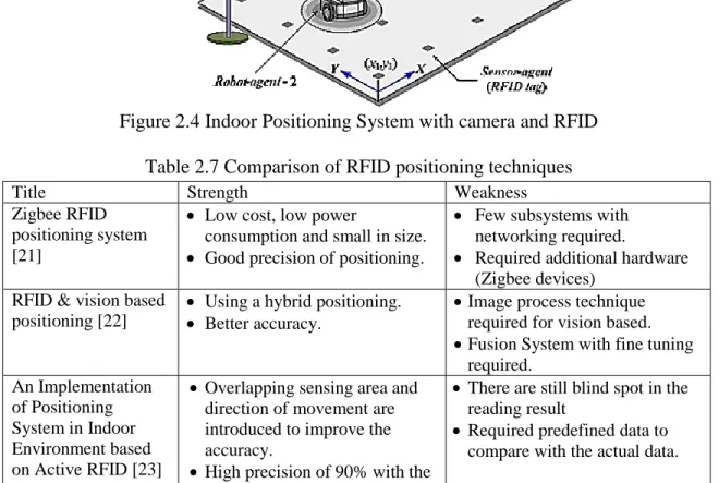
A positioning system with the combination of two sensors which is RFID and camera to track and positioning a robot movement was done by Byoung-Suk Choi and Ju-Jang Lee [20]. As shown in Figure 2.4, a RFID reader was attached to the robot while the RFID tag is placed on the floor. The reader sensed the tags placed on the floor and determined the location of the robot with the information of ID in the tag. To increase the accuracy of the location, a camera was placed on the top of the room to scan and locate the position of the robot by image processing technique.
16
Figure 2.4 Indoor Positioning System with camera and RFID Table 2.7 Comparison of RFID positioning techniques
Title Strength Weakness
Zigbee RFID positioning system [21]
Low cost, low power
consumption and small in size.
Good precision of positioning.
Few subsystems with networking required.
Required additional hardware (Zigbee devices)
RFID & vision based positioning [22]
Using a hybrid positioning.
Better accuracy.
Image process technique required for vision based.
Fusion System with fine tuning required. An Implementation of Positioning System in Indoor Environment based on Active RFID [23]
Overlapping sensing area and direction of movement are introduced to improve the accuracy.
High precision of 90% with the distance interval of 2m
There are still blind spot in the reading result
Required predefined data to compare with the actual data.
Table 2.7 shows the comparison of different type of RFID positioning techniques. The ‘An Implementation of Positioning System in Indoor Environment based on Active RFID’ has a better result compared to other two papers. However, this technique required a predefined database in order to maximum the accuracy of the positioning system.
17
2.4.3. WLAN based Positioning System
Nowadays, there are a lot of wireless technologies available in the industry such as Bluetooth, Infrared, ultrasound and also radio signal. The radio signal technologies included Wireless Local Area Network, Radio Frequency and also radio waves. The radio signal can transmit in a mid-long range which had a better coverage range that compared to other wireless technologies. Wireless Local Area Network (WLAN) provides wireless network communication over a short distance using radio signal or infrared signal instead of traditional network cabling [24]. Wireless Local Area Network usually is used to link a few devices to the access point so that the devices can communicate wirelessly and it also connects the devices to the internet through the access point [25].
2.4.3.1. Type of Wireless LAN
There are total of three types of Wireless Local Area Network connection, which are peer to peer, bridge and wireless distribution system. The peer to peer (p2p) connection allows wireless devices to directly communicate with each other with no intermediate hardware components involved [26]. This connection usually used by two computers so that they can connect to each other and form a network.
Besides that, bridge connection refers to the connection between different networks. Network bridge connection allows multiple network from different connection to communicate with each other while remain separate [27]. There are two method of configuration to establish the group for connection. The first method is autonomous group owner that is group owner set up manually. The second method is negotiation based group creation which the strongest signal device acts as the group
18
owner. There are four types of network bridging technologies such as simple bridging, multiport bridging, learning or transparent bridging and source route bridging.
The wireless distribution refers to the multiple access points are connected together without the use of the wired Ethernet. The access point in the wireless distribution system can be either main, relay or remote base station. The main station is connected to the wired Ethernet while other uses the wireless connection to communicate with the main. Besides that, this connection can also be used as the repeater.
2.4.3.2. IEEE 802.11 Standards
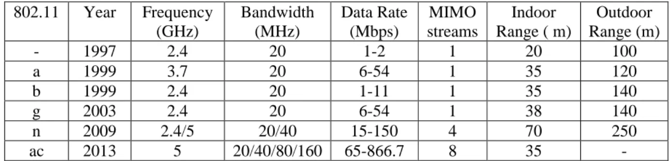
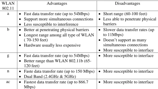
The IEEE 802.11 Standards refers to a family of specifications developed by the IEEE for Wireless Local Are Network (WLAN) technology that is using the carrier sense multiple access and Ethernet protocol for the wireless communication technique. This technique is centralized and is applicable worldwide. Normally, the Wireless Local Area Network used the wired equivalent privacy algorithm as the security enconding to protect the data. Table 2.8 shows the details of each type of IEEE 802.11 Standards while Table 2.9 shows the advantages and disadvantages of each type of IEEE 802.11 Standards.
Table 2.8 Types of IEEE 802.11 Standards
802.11 Year Frequency (GHz) Bandwidth (MHz) Data Rate (Mbps) MIMO streams Indoor Range ( m) Outdoor Range (m) - 1997 2.4 20 1-2 1 20 100 a 1999 3.7 20 6-54 1 35 120 b 1999 2.4 20 1-11 1 35 140 g 2003 2.4 20 6-54 1 38 140 n 2009 2.4/5 20/40 15-150 4 70 250 ac 2013 5 20/40/80/160 65-866.7 8 35 -
19
Table 2.9 Comparison of IEEE 802.11 Standards WLAN
802.11
Advantages Disadvantages a Fast data transfer rate (up to 54Mbps)
Support more simultaneous connections
Less susceptible to interference
Short range (60-100 feet)
Less able to penetrate physical barriers
b Better at penetrating physical barriers
Longest range among all type of WLAN ( 70-150 feet)
Hardware usually less expensive
Slower data transfer rates (up to 11Mbps)
Doesn’t support as many simultaneous connections
More susceptible to interface g Fast data transfer rate (up to 54Mbps)
Better range than WLAN 802.11b (65-120 feet)
More susceptible to interface
n Faste data transfer rate (up to 150 Mbps)
Dual Band (2.4GHz & 5GHz)
More susceptible to interface ac Fastest data transfer rate (up to 866.7
Mbps)
More susceptible to interface
2.4.3.3. WLAN positioning concept
WLAN links wireless devices such as personal computer, laptop and internet-enable mobile phone, provide data exchange and sharing mediums and allows the connection though access points (AP) to the internet wirelessly. The access point (AP) is referred to router or modem. The WLAN technology operates at the frequency of 2.4 GHz for communication regardless of any brand of APs. An AP has wide coverage area of 90 to 180 meters depends on the transmission power of the AP used, thus, the users have high mobility to move around within the local coverage area without worrying about any restriction, disconnection and data loss. Owing to its ease of installation and highly demand of the internet access, Wi-Fi service and hotspot can be found in everywhere like shopping mall, university campus and restaurants for free today.
20
Figure 2.5 WLAN Indoor Positioning Technique
Figure 2.5 shows a sample idea of utilizing the WLAN technology in an indoor positioning system. The positioning technique used a few Access Points to distribute signal with a specified MAC and SSID and used the radio signal strength from each Access Point to calculate the location of the user/object. The radio signal strength detected is converted to a dimensionless value called the Received Signal Strength Indicator (RSSI), which is a popular measurement for the wireless communication field. By applying the signal metric, RSSI, the position of the user/object able to be determine by analysing the signal strength. The accuracy and sensitivity can be improved by adding more Access Points into the system. The Wireless Local Area Network positioning system is a low-cost and high accuracy positioning technique. Therefore, WLAN technology has a high potential in the Indoor Positioning System.
Indoor Positioning System based on Wi-Fi technology also known as Wi-Fi Positioning System (WPS). WPS is a localization technique using wireless access points or wireless routers with the measurement on the intensity of the received signal strength (RSS). Matteo Cypriani, Gilles Delisle and Nadir Hakem adopted a technique called
Destination Base stations
Base stations Mobile stations
It is in the direction of 2 o’clock, 2 meters away
21
Owl Positioning System (OwlPS) to locate an object in the underground mine tunnels [28]. OwlPS was originally published by the University of Franche-Comté in France and it was based on the IEEE 802.11 wireless network. In this project, OwlPS was used in underground tunnel to provide the mine workers and their equipment with the positions in the tunnel. Besides that, the OwlPS is also useful in other application such as asset management. However, to setup an OwlPS system is very time consume. A few Access Point and router need to be setup in order to provide a large area of coverage. Moreover, the signals of the radio waves propagate along the tunnels and cannot pass through walls.
From the literature, the WLAN positioning is found to the most suitable for the indoor positioning as it provides a low cost, low complexity and high accuracy positioning by only using the fingerprint method to compare the RSS of the WLAN. The accuracy of the WLAN has been improved to around 3m that is favorable for indoor positioning. The factor of error is identified and it is useful for precaution and future development.
Table 2.10 Comparison of WLAN positioning technique
Title Strength Weakness
RSSI based WLAN Indoor Positioning with Personal Digital Assistants [29]
Using 3 different filtering techniques.
Mean distance of each filter at around 1-3m
RSS fingerprint method is proven to be effective.
Range of the RSS change rapidly
The change of the distance does not goes linearly with the RSS value.
The multipath effect is not discussed in the paper. An Effective
Scheme for WLAN based Fingerprint Positioning System [30]
Introduce K Nearest Neighbourhood method with a great performance.
Maximum error of the fingerprint around 30m.
Mean error at around 2m.
The relationship of the RSS and the positioning is not related
The access point density increases to improve the accuracy
22
Table 2.10 Comparison of WLAN positioning technique (Continued) An Indoor Positioning Algorithm based on Received Signal Strength of WLAN [31]
Improved fingerprint method is introduced.
The accuracy of the KNN and fingerprint is at around 3m.
Source of the error of the positioning is not specified in the paper
Composite Indoor Localization and Positioning System Based on Wi-Fi Repeater Technology [32]
Using combination of Time of Arrival (TOA) and Angle of Arrival (AOA) to backup each other.
Able to locate location at any point without predefined database
Accuracy of 1.5m
Source of the error of the positioning is not specified in the paper
Indoor Wi-Fi positioning algorithm based on combination of Location Fingerprint and Unscented KaIman Filter [33]
Using Dead Reckoning method
Combining of Location Fingerprint and Unscented Kalman Filter
Provides a considerable range of accuracy
Source of the error of the positioning is not specified in the paper
Table 2.10 shows the comparison of WLAN positioning technique. From the 5 paper, the 5 different WLAN positioning systems also provide a positioning system with accuracy around 3 m. This proves that the WLAN positioning system using the RSS fingerprint method is the most suitable for the indoor positioning system. It provides an indoor positioning with a low cost, low complexity and high accuracy positioning.
2.5. Comparison of Positioning Technologies
Table 2.11 Comparison of Positioning Technologies Positioning Technology Advantages Disadvantages Global Positioning
System (GPS)
Worldwide coverage
Accuracy of 5-6m at outdoor environment
Line of sight is needed
Serious multipath effect
Low signal / no coverage in indoor environment
23
Table 2.11 Comparison of Positioning Technologies (Continued) Wireless Local Area
Network (WLAN)
Wide coverage area (~100m-140m) High accuracy Low cost/Free Available in most building Time consuming to collect data Hardware setting is needed Multipath effect Bluetooth Trusted private
connection
High security
Short range
communication (~10m)
Pairing process needed before communication Radio Frequency
Identification (RFID)
Wide coverage area (active tag ~80m-100m) Unique identification On board battery needed Frequency interference Multipath effect
From Table 2.11, the comparison of the few possible technologies, RFID and the WLAN positioning system offer a better quality of positioning with better accuracy and less error compared to other positioning technologies. Both technologies have a wide coverage area of around 100m and have better performance in indoor environment. The RFID positioning technique provides a unique identification to the reader so that the identity of the object and the position of the object can be identified. On the other hand, the WLAN positioning provides a private positioning only for the certain user/object and keeps the identity private. Besides that, the penetration power of the WLAN signal is strong enough to propagate through the indoor environment and provide the signal to all the space. Furthermore, the WLAN positioning is the most suitable for the indoor positioning as it provides a low cost, low complexity, less hardware needed and high accuracy positioning by only using the fingerprint method to compare the RSS of the WLAN. In addition, there are few proposed techniques that can be used to perform the positioning system has also make the WLAN become a better than RFID.
24
2.6. Indoor positioning Method and parameter
There are few methods or parameters can be use in the Indoor Positioning System. An Indoor Positioning methods or parameters refer to the methods or parameters that use to detect the location of a user/object in an indoor environment. Each type of method uses different parameter or different approach to identify the position of the user/object. In this chapter, a few type of method such as ‘Location Fingerprint of Received Signal Strength’, ‘Time of Arrival for Trilateration’ and ‘Angle of Arrival for Triangulation’ have been identified to understand the method and its performance in order to choose the suitable method that can be implemented in the WLAN Indoor Positioning System.
2.6.1. Received Signal Strength (RSS) Location Fingerprint
The Received Signal Strength (RSS) is a measurement of the level of the power present in a received radio signal by the receiver. The signal strength means that the magnitude or level of electric field that transmitted from the antenna. The RSS location fingerprint is widely used in the positioning system as it does not require complex theory or calculation to identify the location of the user/object.
The RSS location fingerprint method requires the positioning system to pre-collect a set of database with the RSS values on each particular location. The database of the collected RSS on the particular location will then store in the positioning system. When the positioning system start locating the location of the user/object, the positioning system will compare the RSS of where the user/object standing and compare with the database to identify the location of the user/object.
![Table 2.1 GPS Frequency Usage and Application[4], [5], [6]](https://thumb-us.123doks.com/thumbv2/123dok_us/422811.2548564/18.918.165.807.847.1094/table-gps-frequency-usage-application.webp)
![Table 2.3 Bluetooth classes with the effective range [11]](https://thumb-us.123doks.com/thumbv2/123dok_us/422811.2548564/21.918.203.782.269.381/table-bluetooth-classes-effective-range.webp)
![Table 2.6 Type of RFID tag [18] [19]](https://thumb-us.123doks.com/thumbv2/123dok_us/422811.2548564/25.918.166.829.131.582/table-type-rfid-tag.webp)