Secure and Privacy-Preserving Communication in Hybrid
Ad Hoc Networks
Srdjan ˇ
Capkun
1, Jean-Pierre Hubaux
2and Markus Jakobsson
31,2
Laboratory for Computer
3RSA Laboratories
Communications and Applications (LCA)
174 Middlesex Turnpike
Swiss Federal Institute of
Bedford, MA 01730
Technology Lausanne (EPFL)
USA
CH-1015 Lausanne, Switzerland
[email protected], [email protected] [email protected]
ABSTRACT
We present a scheme for secure and privacy-preserving com-munication in hybrid ad hoc networks. Our scheme en-ables users to secure communication and to protect their anonymity and location privacy. Our approach is based on frequently changing node pseudonyms and cryptographic keys, which enable users to avoid being identified by the lo-cations they visit, or by the type of traffic they generate. We show how our scheme can be effectively used for secure and private routing in hybrid ad hoc networks. We study the robustness of the proposed solution with respect to various attacks. We further show that the proposed solution intro-duces a very moderate overhead to the network operation.1
Categories and Subject Descriptors
C.0 [Computer-Communication Networks]: [Security and protection]
General Terms
Security, Anonymity, Location, Privacy
Keywords
Anonymity, Privacy, Mobile Networks, Hybrid Networks
1.
INTRODUCTION
Ad hoc networks are appealing for a number of reasons, in-cluding their flexibility of deployment. However, these net-1The work presented in this paper was supported (in part) by the National Competence Center in Re-search on Mobile Information and Communication Sys-tems (NCCR-MICS), a center supported by the Swiss Na-tional Science Foundation under grant number 5005-67322
(http://www.terminodes.org).
EPFL-IC Technical report no. IC/2004/10
works are known to have limited scalability, and do not pro-vide, as such, an access to large scale networks such as the Internet. For this reason, several researchers have recently studied the possible interconnection of ad hoc networks to a backbone by means of one or several access points [25]. In this way, a mobile station can communicate with an access point over several other mobile stations in a multi-hop fash-ion. It is reasonable to assume that one or severalnetwork operators are in charge of the proper operation of such net-works, and receive an appropriate remuneration from their subscribers.
This approach seems to be promising, as it combines the best of both worlds: the extended reach and scalability of classical, large-scale wired networks with the flexibility of ad hoc networks; in this paper, we call a network resulting from this combination a “hybrid ad hoc network”. A possible in-carnation of such a network is a multi-hop Wi-Fi network. In this case, the network operator would typically be a Wire-less Internet Service Provider. Other examples of hybrid ad hoc networks include multi-hop cellular networks [37]. In order to gain acceptance from the users, hybrid ad hoc networks must provide an appropriate level of security. In-deed in general, a user trusts his network operator, but he does not trust the other users; he may also distrust the op-erators of the networks in which he roams.
The paper addresses both routing security and privacy preservation; we will show that the two mechanisms can be embedded in the same protocols.
A number of papers [16, 28, 32] have recently addressed the problem of secure routing in ad hoc networks. We base our threat analysis on the extensive description of attacks provided by these research efforts.
As for privacy, we show how to provide the two following features: anonymity and location privacy. Privacy Interna-tional [38] defines four categories of privacy: information pri-vacy, bodily pripri-vacy, communication pripri-vacy, and territorial privacy. Location privacy is a particular case of information privacy and can be defined as the ability to prevent other parties from learning one’s current and past locations [3].
Anonymity can be defined asthe state of being not identifi-able within a set of subjects called the anonymity set[30]. We propose a set of protocols that protects users’ anonymity and location privacy. More precisely, our scheme enables each mobile node to keep its location and its identifier hid-den from other network nodes. We assume, however, that the network operator has access to the locations and the identifiers (and potentially also to the user identities) of the registered mobile nodes. Our approach is based on the frequently changing of node pseudonyms, so that the users avoid being identified by the locations they visit, or by the type of traffic they generate. We do not restrict our investi-gation to privacy, but we also investigate how privacy can be achieved and user accountability enforced. In our scheme, accountability is enforced through dynamic, but verifiable, cryptographic keys used by the nodes to secure their com-munication.
Although originally designed for data-centric hybrid ad hoc networks, our scheme can be, with some minor modifica-tions, used to enable secure and privacy-preserving commu-nication in hybrid voice-centric networks.
In this paper we specifically: (i) present an overview of pri-vacy threats, (ii) propose a scheme for secure and pripri-vacy- privacy-preserving communication, and (iii) present a quantitative analysis of privacy.
The rest of the paper is organized as follows. We introduce our system and security model in Section 2. In Section 3, we describe privacy challenges and goals. In Section 4, we describe the basic mechanisms of our scheme. In Section 5, we provide a detailed description of our privacy preserv-ing routpreserv-ing protocol. In Sections 6 we quantify the level of achieved privacy, analyze security and the performance of our scheme. We describe the related work in Section 7. Finally, we present our conclusions in Section 8.
2.
SYSTEM MODEL
In this section we describe our network model along with the security and trust assumptions.
2.1
Network model
Our system consists of a set ofaccess points, mutually con-nected via a high-speed backbone, and a set ofmobile nodes. Each access point controls a bounded geographic area called acontrol area. All communications between nodes and be-tween a node and a access point are wireless. We assume that the access points and mobile nodes have the same power range, and that the latter is smaller than the size of the con-trol area. We further assume that all links are bi-directional, meaning that the link between two nodes (or between a node and a access point) exists only if both mobile nodes are in each others’ power range. This means that the majority of nodes in the control area will not be able to communicate di-rectly with an access point, but will use other mobile nodes as relays to reach the bases stations.
In order to make our study as generic as possible, we will consider that both hosts involved in the communication ac-cess the backbone in a multi-hop fashion.
When a source node S wishes to send a message m to a destination D, it transmits a packet p containing m to a first access pointBSS(which is typically the geographically closest access point to S) using an uplink protocol. If the destination node is mobile, the packet is then sent to a sec-ond access pointBSD, which is typically the closest station to the destination D. Then,BSD transmits a packet con-taining m to the intended destination D using a downlink protocol. If the destination node is a fixed (internet) host, the packet is routed through the fixed network using tra-ditional network protocols. Both the uplink and downlink protocols are multi-hop, i.e., they require the participation of nodes on the route. These nodes are typically peers of the source and destination. Later we detail the two protocols. We assume that all nodes in the control area are loosely synchronized; we later describe how to avoid clock skew.
2.2
Security and Trust
We initially assume that all access points are run by the same operator (we describe later how to loosen this assump-tion). Each mobile node has a uniqueidentifier, and carries asecret key, both of which are also known by the network op-erator2. Neither the identifier nor the secret key is disclosed to other parties. Like in cellular networks, there is a contrac-tual agreement between a user of the mobile node and the network operator, which defines mutual rights and obliga-tions. This contract defines policies that are enforced by the operator, charging, privacy protection and tariff. Notably, the network central authority (through its access points) acts as a network supervisor, and protects the network from user misbehavior. The access points therefore monitor node behavior, maintain node reputations and detect node misbe-havior. As a reaction to node misbehavior, central authority limits node’s access to a subset of services or excludes the node from the network, temporarily, or permanently, by re-voking its membership certificate.
The network membership is controlled by the network cen-tral authority and each node carries a certificate of member-ship that it uses to prove to other nodes that it is a part of the network. Furthermore, each node is able to uniquely sign a message such that other users can verify that the message originated from the legitimate network node, but no one, except the central authority can identify which node signed the message. This is important for ensuring that the exe-cution of network protocols is both secure and anonymous, and that the users are accountable for their behavior by the uniqueness of their signatures.
However, the users do not have mutual contractual agree-ments, and are not willing to trust each other with their identities and locations, nor do they want to trust each oth-ers’ nodes to correctly execute networking functions (for-wards packets, or provide accurate routing information). To summarize, we assume that each node carries a secret key shared with the network central authority and a set of 2For simplicity, we assume that the network operator dis-tributes secret keys and node identifiers to the access points under its control. In reality, nodes would establish shared secret keys with the access points, using a certificate issued to them by the central authority.
keys, certified by the operator, which it uses to secure the operation network protocols.
3.
PRIVACY GOALS AND CHALLENGES
In this section we outlay our main design goals and privacy challenges for hybrid ad hoc networks.
3.1
Design goals
We want to design a system that enables the users anony-mous and location private communication. Location pri-vacy is the ability to prevent other parties from learning one’s current and past locations, and anonymity is the state of being not identifiable within a set of subjects called the anonymity set. Here, we define these terms more precisely in the context of hybrid ad hoc networks.
One of the main goals of our scheme is to enable source and destination anonymity. Source anonymity is defined as the property that a particular message is not linkable to any source, and vice-versa. A similar definition applies to destination anonymity. Unlinkability in this context means that the probability that a particular message was sent by a given source and/or received by the same destination is the same as imposed by the a priori knowledge. This means that the process of sending and/or receiving messages does not reveal any additional information about the identities of the source and/or destination that was not already known to the attacker prior to the message transmission.
In our scenario, we want to achieve the following. Clearly, the source S needs to know the identity D of the destina-tion, but not its location. The access points need to know who the source and the destination are, and where they are located, so as to route the messages accordingly. The ac-cess points need to know the identities of the source and the destination, in order to check if they are registered network nodes. However, nobody else, including the nodes on the route of the packet, should be able to infer either the source of any packet that they observe, or its destination. Further-more, nobody should be able to infer where the nodes are located. This means that neither a node not registered to the network, nor a registered network node, could infer the identities of the communicating parties or their locations by observing network traffic. Here, we consider that a loca-tion of the node is compromised if an attacker can infer the distance in terms of number of hops (relay nodes) from the node to the access point(s), or its exact physical location. Note that we do not assume any sophisticated mechanisms for node positioning, such as the use of GPS.
Anonymity can be measured with various metrics, among which two are the most common: one based on anonymity set and other based on entropy. In our system, if the attacker holds the list of registered network nodes, the maximum degree of anonymity that the system can provide is proportional to the size of the list; in this case, the list corresponds to the anonymity set of the network. We will assume that the network has a sufficiently large anonymity set, so that it thus provides a reasonable anonymity to the users. The second metric is more sophisticated and is com-puted based on probabilities assigned to each identity (e.g., the probability that a given user is the originator of a mes-sage). In our analysis, we will reason in terms of both of
these metrics.
3.2
Privacy challenges
In hybrid ad hoc networks, users’ privacy is at risk from various threats. Here we overview the most important ones.
Malicious/Compromised users
In hybrid ad hoc networks, nodes need to maintain their neighborhood information for various reasons, mainly for routing and packet forwarding and as a prerequisite to run-ning distributed network algorithms (e.g., positiorun-ning). Thus, to enable proper network operation, the nodes would need to disseminate to other nodes their identifiers, topology information and/or locations. This information would then be freely available to any registered network node, or even to a passive attacker that observes network communication. It is thus clear that even a single node, by logging the iden-tifiers of its neighbor nodes, can gather much information about other users’ behavior (e.g., if the attacker stays at the same location for a longer time, it can observe the frequency at which other nodes visit this location).
Active attacks can be far more sophisticated. A simple ample of such an attack is when an attacker periodically ex-plores network topology by asking for routes to other nodes. Another possible attack is if an attacker positions itself close to the access point and thus gathers the information about the communication between nodes. If the routing protocol is not secure, the attacker could even, regardless of its loca-tion, advertise the shortest route to the access point, collect the the traffic, and analyze it to observe which pairs of nodes currently communicate, and what are the nodes’ distances to the access point(s). Another important set of attacks are those launched by communication parties against each other, meaning that a source wants to discover a location of the destination, or vice versa.
Untrusted network operators
Nodes roaming in untrusted networks are susceptible to at-tacks from malicious network operators. Unless the user does not protect its privacy, an untrusted operator could easily trace users and/or reveal their true identity. This is especially important as the number of network operators in hybrid ad hoc and multi-hop WiFi networks might be sig-nificantly larger than the number of operators of today’s cellular networks. It will be thus hard to regulate all oper-ators and risks of privacy violation would be higher.
Unique network addresses, interface addresses and cryptographic keys
One of the main potential causes of users’ privacy vulnera-bilities in hybrid ad hoc networks could be the uniqueness of the identifiers and keys that the nodes use to communicate and to secure their communication. Typically, each node uses a static and unique network address to perform network layer operations, and static and unique interface addresses for media access control (MAC) operations. Furthermore, to secure their mutual communication, nodes need to establish keys between each other and with the access points. These keys enable nodes to authenticate the source of the messages that they receive and to protect the confidentiality and in-tegrity of the messages that they send. The fact that the keys are unique either to the node (public key
cryptogra-phy), or to the pair of nodes (symmetric key cryptography) enables a malicious user to track other users.
Radio fingerprinting
Besides unique identifiers, the nodes are equipped with ra-dio transceivers whose emitted signals contain unique fin-gerprints [34]. An attacker can, therefore, identify a mo-bile device by the unique “fingerprint” that characterizes its signal transmission. This process is normally used by cel-lular network operators to prevent cloning fraud; namely, a cloned phone does not have the same fingerprint as the le-gal phone with the same electronic identification numbers. This technique can be used by the attacker to track mobile nodes, given that the attacker remains in the power range of the node. A similar technique is that an attacker observes the signal to noise (S/N) ratio of nodes’ signals. If a node is static for a given period of time and uses pseudonyms to pro-tect its identity, the attacker can infer that the pseudonyms are generated by the same node since the S/N ratio did not change. Recent measurements in WiFi networks [13] show that S/N based attack can significantly reduce the capability of the nodes to prevent tracking.
4.
OVERVIEW OF THE SOLUTION
In this section, we introduce two important ingredients of our privacy preserving scheme: node pseudonyms, and dy-namic public keys. At the end of the section, we define the notation that we use in the paper.
4.1
Node pseudonyms
As we mentioned earlier, each node shares a secret key with the access point. This key and the node’s true identity are known only to the node and to the authority that controls the access point. A node pseudonym changes over time, according to the following equation:
PS(t) =HM ACKS(IDS, t)
where PS is the node pseudonym at time step t, HMAC is a keyed hashing function,IDS is the true node identity, andKSis the secret key that the node shares with the cen-tral authority. HMAC can be implemented by any iterative cryptographic hash function, such as, MD5 or SHA-1. The cryptographic strength of HMAC depends on the properties of the underlying hash function. Thus, the pseudonyms of the node will be of the same size as the output of the hash function that is used for keyed hashing; if used with SHA-1, the HMAC output is 160 bits long. Depending on the size of each control area, and the number of nodes in the con-trol area, the pseudonym length can be reduced, without significantly increasing the probability of identifier collision. For this, the pseudonyms obtained from the original equa-tion can be truncated or hashed into shorter bit strings. To guarantee that the access point and the node generate the same node pseudonyms at the same time, the time is slot-ted andt as an input to the HMAC function represents a time step, and not the actual timestamp provided by the de-vices. We later discuss how to choose the time granularity. Alternative ways to generate node pseudonyms can be envi-sioned. One solution consist in generating node pseudonyms by making use of pseudo-random number generators.
4.2
Dynamic keys
To ensure that the communication between nodes and the access points is performed through legitimate nodes, the nodes that belong to the same control area need to be able to verify that the messages they receive come from the reg-istered network nodes. At the same time, we need to ensure that the central authority can track the actions of each in-dividual node and that the misbehavior of nodes can thus be detected and sanctioned.
Securing ad hoc routing protocols in multi-hop wireless net-works is notoriously hard. Researchers have identified a number of attacks that can be mounted equally against pure ad hoc and hybrid ad hoc networks. These attacks include: excessive route requests, blackhole attack [16], rushing at-tack [18], wormhole atat-tack [15], etc. In hybrid ad hoc net-works, due to the presence of access points, routing will be easier to secure, as access points can control node behav-ior, act as on-line central authorities and sanction misbe-havior. Nevertheless, like in ad hoc networks, to protect the network against these attacks, nodes need to be able to authenticate each others’ messages and even to keep their communication confidential. For this, nodes need to share secret keys or hold authentic public-keys. We propose here, a privacy-preserving key management scheme for hybrid ad hoc networks.
A naive solution would be to make use of control area-wide secret keys. This scheme assumes that the nodes that belong to the same control area share a common secret key. This key is generated and in an authentic and confiden-tial manner distributed to all the nodes in the control area by the access point that controls the control area. The key is periodically updated by the access point. The introduc-tion of the control area-wide key enables each node to verify if other nodes belong to the network, without revealing any information about its identity or the identity of the other nodes. However, if any of the control area nodes is com-promised, the attacker can use the control area-wide key to attack the network without being detected. Furthermore, the access point will not be able to detect node misbehavior as each node uses the same control area key for authentica-tion to other nodes.
Given the drawbacks of the control area-wide key scheme, we propose a different scheme that we call adynamic pub-lic key scheme. In this scheme, along with its changing pseudonym, each node A holds a set of public/private key pairs (P KA1/P rKA1, ..., P KAn/P rKAn) and certificates signed by the central authority, certifying these keys. This set can be generated either by the node or by the central authority. If it generates the key pairs, the node sends the public keys from the pairs to the central authority, which certifies them and sends the certificates back to the node. If the public/private key pairs are generated by the central au-thority, they are sent to the node along with the certificates containing the public keys. The certificates of the public keys signed by the central authority certify only that the holder of the private key corresponding to the public key in the certificate is a registered network node. The certificates have the following format:
CertkA= [P KAk, SIGP rKAuth(P KAk)]
and P rKAuth is the private key of the central authority3. We note here that the exchange of public/private key pairs between a node and the central authority is protected by the key shared between the node and the central authority. A node uses its public/private key pairs to establish sym-metric secret keys with its neighbors. Each time that a node changes its pseudonym, it changes the public/private key pair and establishes new symmetric keys with its neighbors. If a node encounters a new neighbor, it establishes a secret key with the new neighbor using the same public/private key that it uses for this period. Before a node runs out of pub-lic/private key pairs, it generates some new pairs and sends them to the central authority for certification. The central authority replies with the certified keys. This update of public keys and certificates can be performed in a number of ways, through periodic updates, or by piggybacking the certificates on uplink and downlink traffic. Moreover, as we discuss in Section 6, the nodes can reuse the private/public key pairs after some time, without compromising their loca-tion and identity privacy.
The nodes do not have to change their public keys (and pseudonyms) at a given frequency, but this change can be event driven (e.g. when a node starts a new session). For efficiency, the speed of key changes can be limited by the access points, but each user can determine if it wants its pseudonyms and keys being changed with a lower frequency. To enable this, the nodes need to change their keys and pseudonyms at frequencies which are related to the given basic frequency4.
We will comment briefly on other alternatives to this pro-posal in Section 7.
In our proposal, mutual node authentication is performed automatically, so that routing is secured permanently. How-ever, the system can be also designed in such way that nodes perform mutual authentication only if they are requested to do so by the access point; notably, if the access point de-tects misbehavior within a given region of its control area, it can enforce mutual node authentication in that region to prevent future misbehavior. This optimization can reduce the communication overhead introduced by the dynamic key scheme.
Update frequency
The frequency of the key and pseudonym change can be chosen arbitrarily by the base stations and mobile nodes. To increase the level of anonymity and location privacy, nodes should increase their update frequencies. However, as we show in Section 6.3, pseudonym/key change frequency is only one of the factors that determines the degree of privacy that can be achieved, whereas others are related to node mobility and attacker strength. We further conclude that in our scenario the sufficient frequency of pseudonym change is in the order of 1/min.
4.3
Further notation
3Note that neither the identity of the node nor the position of the key in its key set are disclosed to other nodes. 4This basic frequency is a system parameter and is con-trolled by the access point.
ByBSSwe denote the access point that controls the control area in which nodeS is located. ByM ACK(m) we denote the message authentication code of messagemwith the key K. A one-way hash function on messagem we denote by H(m). ByEK(m), we denote a message encrypted with the key K, and by SIGP rK(m) we denote the signature over messagemwith the private keyP rK.
5.
PRIVACY PRESERVING ROUTING
In this section, we introduce thePrivacyPreservingRouting protocol (PPR). This protocol consists of four sub-protocols that we describe in brief as follows. We first describe the
downlink protocol that is used for routing from the access point BSD to the destination node D; we then describe the uplink protocol that is used to route packets from the source node S to the first access point BSS; next we de-scribe the inter-station protocol used to communicate mes-sages between access points; finally, we describe the book-keeping protocol that is used by the access points to keep track of node locations, pseudonyms and network topology.
5.1
Protocol overview
In this section we briefly overview PPR.
Downlink. As we will show later in more detail, the down-link protocol is a source routing protocol and it is a rather straightforward. The access pointBSD first determines the route to the destination D, given the information that it has about the location and topology of the nodes in its control area. It computes the current pseudonyms of the nodes on the route, and includes them in the packet, after which it sends the packet to the first node on the route. The first node, addressed by its pseudonym, removes its pseudonym descriptor from the packet and transmits the resulting packet to the next node on the route. Eventually, and assuming the route is not broken, the packet is received by the intended destinationD.
Uplink. It is evident that a simple modification of the downlink protocol cannot be used for uplink communica-tion. The reason is that the packet originator S does not know the pseudonyms of the nodes on the path to the access point BSS, nor does it have access to the database speci-fying the location of various nodes. For this reason, we de-signed the downlink protocol as a distance vector protocol. In fact, given the requirements on privacy, nodes will not build routing tables, as these are irrelevant in that they are constantly changing with the rapid updates of pseudonyms. Instead, each node will keep track of its distance (in terms of number of hops) to the closest access point, along with the time at which this distance was known to be correct. When a packet is sent from one node to another, the send-ing node will announce its believed distance to the access point, and its neighbors will determine whether to route the packet based on this information. Nodes will update the distance information over time to reflect the changes of the topology.
Inter-station. Here we briefly describe the inter-station protocol used for the communication between two access points, one controlling the control area of the source, and the other controlling the control area of the destination. If both access points are under the control of the same authority,
the inter-station protocol is straightforward. Each uplink packet that arrives to the source access pointBSSis simply forwarded to the destination access pointBSD, where the message is verified. Subsequently, a corresponding downlink packet is created, encrypted with the keys that the access point shares with nodes on the path, and sent to the destina-tion. If the node does not trust the access point controlling its control area, the inter-station protocol is somewhat more complex. We elaborate this further in Section 5.4.
Book-keeping. The access points keep records of the iden-tities, pseudonyms, keys and distances of the nodes in their cells. Based on trust and pre-established policies, the access points also exchange this information. The databases are indexed by all five of these types of information, and are up-dated by piggybacking information on uplink messages and by periodic updates. Not only access points, but also mobile nodes keep information about their location and distance to the access points. This information is updated either from the downlink traffic or upon the execution of the periodic updates.
Discussion. We note here that the PPR is a proactive routing protocol, and that other, potentially fairly differ-ent solutions for routing in hybrid ad hoc networks can be proposed. Nevertheless, as we will show, the way that se-cure and privacy-preserving communication is implemented in PPR can be a useful inspiration for making other (pos-sibly reactive, or proactive-reactive) protocols secure and privacy-preserving.
5.2
Uplink
In this section we describe the uplink protocol in more detail. As we already described, nodes establish symmetric secret keys with their neighbors. As we show, we use these keys to secure network protocols and privacy of users.
The uplink protocol works as follows. Each node regularly updates the list of its neighbors (their pseudonyms) and their distances to the access point. Each neighbor and dis-tance update are properly secured with the keys that the node shares with its neighbors. When the nodeS needs to send a packet, it chooses the next hop node from the list of its neighbors and forwards the packet to the chosen node. The choice of the next hop node is based on the distance information provided by the neighbors; typically, the source forwards the message to the node that is the closest to the access point. Each consecutive node repeats this procedure until the message reaches the access point. The nodes main-tain their distances to the access point with a book-keeping protocol, as described in Section 5.5.
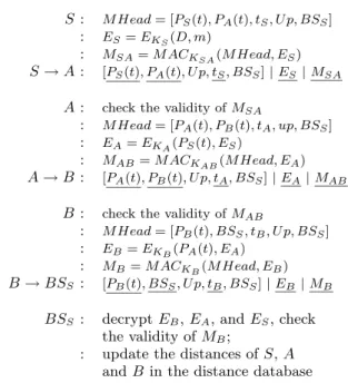
An example of the uplink protocol execution is shown on Figure 1. The figure shows the message evolution from the message source node S, through nodes A and B, to the access pointBSS.
Here, U p means that the message is an uplink message, tS, tAandtB are timestamps that guarantee message fresh-ness,BSS is the identifier of the access point to which the message is sent,EKS(D, m) is the encrypted identifer of the
message and of the destination identifier (it can only be de-crypted by the access point), and m is the message from
UPLINK PROTOCOL
S: M Head= [PS(t), PA(t), tS, U p, BSS]
: ES=EKS(D, m)
: MSA=M ACKSA(M Head, ES)
S→A: [PS(t), PA(t), U p, tS, BSS]|ES|MSA A: check the validity ofMSA
: M Head= [PA(t), PB(t), tA, up, BSS]
: EA=EKA(PS(t), ES)
: MAB=M ACKAB(M Head, EA)
A→B: [PA(t), PB(t), U p, tA, BSS]|EA|MAB B: check the validity ofMAB
: M Head= [PB(t), BSS, tB, U p, BSS]
: EB=EKB(PA(t), EA)
: MB=M ACKB(M Head, EB)
B→BSS: [PB(t), BSS, U p, tB, BSS]|EB |MB BSS: decryptEB,EA, andES, check
the validity ofMB;
: update the distances ofS,A andB in the distance database
Figure 1: An example of the run of the uplink pro-tocol. The fields changing from the previous hop are underlined.
S intended for the destinationD. In each packet, the first pseudonym in the message represents the message source and the second pseudonym represents the intended message destination.
MSA is the MAC of the packet content, computed by the sourceS, to prove to the forwarding node (A) thatS is in-deed a registered network node and that the packet content was not modified. The secret keyKSA is a key shared be-tweenAandSand it is established through the dynamic key scheme prior to the protocol execution. When the neighbor Aof the sourceS receives the packet, it checks the validity ofMSA, and encrypts the source node pseudonym concate-nated to the received encrypted message hash ES with the keyKAthat it shares with the access point. It then replaces ES with a newly createdEA, replaces the distance informa-tion in MHead with its own distance, and replaces the MAC received fromSby a new MAC computed with the key that it (A) shares with the next forwarding node (B). Then, A forwards the message to B. A similar operation over the message is performed at each node that forwards the mes-sage. Per-hop re-encryption of the messagemis important so that the access point can verify the hop count and the identities of the nodes on the routes.
Encryption of the message and of the destination by the source guarantees that no one butBSS can infer the iden-tity of the destinationD. The re-encryption of message m by all the nodes on the route guarantees that the message cannot be tracked by an attacker. Specifically, at each node, the message is re-encrypted and therefore altered, so that an attacker will not be able to track the messages in the net-work. This is especially important if the attacker controls several nodes. The node’s location privacy is protected by
its pseudonym and by the fact that its distance to the ac-cess point does not propagate any further than its one-hop neighborhood, so that most of the nodes will not be able to link not even the node pseudonyms with their distances to the access point.
However, in the proposed protocol, some information within the messages is still sent in the clear. Specifically, node pseudonyms are sent in the clear to enable nodes to ef-ficiently verify if the messages are intended for them. Node pseudonyms could also be hidden from passive attackers by encrypting them with the keys shared between nodes. How-ever, this would require each node to try to decrypt the des-tination addresses of all messages that it collects on its inter-face. Furthermore, even if node pseudonyms are encrypted, the same problem would appear with interface identifiers and interface pseudonyms. As with node pseudonyms, in-terface pseudonyms can be hidden, but also at the expense of efficiency.
5.3
Downlink
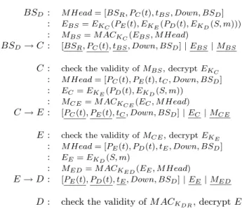
In this section, we describe the downlink protocol for the communication between the access pointBSD and the mo-bile nodeD. We assume that the messagem, sent by node S reached BSD, and needs now to be routed to node D. We also assume that the access point has information about the topology of its control area, which it obtained by means of the book-keeping protocol. Thus, the access point knows the optimal route to the nodeD and sends the message to Dvia that route. An example of the downlink protocol exe-cution is shown on Figure 2. In this example the path from the access point to nodeDcontains two nodesC andD. Here,Downfield denotes that the message is sent on a down-link,tBS, tC andtEare the timestamps that guarantee that the messages are fresh, BSD is the identifier of the access point that sent the message,EKD(S, m) is the identifier of
the sourceSand the messagemencrypted by the key shared between the access point and the destination,PD(t), PC(t) andPE(t) are the pseudonym of the nodesD, C and E at timet, and m is the message sent by S forD. KCE and KEDare the symmetric keys thatCandE,EandD pair-wise share. The integrity, authenticity and confidentiality of the message and of the source identifier are protected by the encryption of the message by a secret keyKD that the access point shares with the destinationD. After creating the downlink packet, the access point sends it to the first node on the route toD (in this case nodeC, addressed by its pseudonymPC(t)). Node Cthen verifies if the message truly originated from the access point by decrypting EKC
and verifying the packet content MAC MBS. If the mes-sage is valid,C forwards the message to the next node on the list (nodePE(t)), but decryptsEKC. NodeEthen
per-forms the same decryption, verification and reduction, and forwards the message to the next node on the list. This is repeated until the message reaches its destination. At the destination, nodeD verifies the packet authenticity and in-tegrity by checkingMED, and decrypts the message and the identity of the message source.
Here, like in the uplink protocol, the per-hop changing packet content prevents attackers from tracking the message through the network and the node pseudonyms are not
for-DOWNLINK PROTOCOL
BSD : M Head= [BSR, PC(t), tBS, Down, BSD]
: EBS=EKC(PE(t), EKE(PD(t), EKD(S, m)))
: MBS=M ACKC(EBS, M Head)
BSD→C : [BSR, PC(t), tBS, Down, BSD]|EBS|MBS C : check the validity ofMBS, decryptEKC
: M Head= [PC(t), PE(t), tC, Down, BSD]
: EC=EKE(PD(t), EKD(S, m))
: MCE=M ACKCE(EC, M Head)
C→E : [PC(t), PE(t), tC, Down, BSD]|EC |MCE E : check the validity ofMCE, decryptEKE
: M Head= [PE(t), PD(t), tE, Down, BSD]
: EE=EKD(S, m)
: MED=M ACKED(EE, M Head)
E→D : [PE(t), PD(t), tE, Down, BSD]|EE|MED D : check the validity ofM ACKDR, decryptEE
Figure 2: An example of the run of the downlink protocol. The fields changing from the previous hop are underlined.
warded further then the nodes’ neighborhoods.
If the route is broken and the message delivery fails, the node that is not able to forward the message, reports the broken link to the access point, that updates the route and re-sends the message.
5.4
Inter-station protocol
As we already described, if all access points are controlled by the same authority, the inter-station protocol is relatively straightforward. Each uplink packet that arrives to the source access pointBSSis simply forwarded to the destina-tion access pointBSD, where the message is decrypted and MACs are verified. Subsequently, a corresponding downlink message is created, encrypted with the keys that the access point shares with nodes on the path, and sent to the des-tination. The inter-station protocol is somewhat different if the node (source/destination) does not trust the access point controlling its control area.
We consider the following scenario: a node S is situated in the control area controlled by an untrusted access point BSU, which is controlled by an untrusted network operator N U. However,S does not trustBSU either with its iden-tity or with its keys, but wants, nevertheless, to establish communication through it. Note here that we assume that BSU is at all times connected to the home networkHNS of S through a high speed link. Here, there are two issues related to trust. Node S does not trust N U either with its identifier or with the identifier of the destination node, but only shows to N U its pseudonyms. However, in order to route packets to S, BSU needs to know its distance in hops toS, and the location ofS in the topology of its con-trol area. This already reveals some information about S to BSU, but hiding this information from BSU would be difficult to achieve efficient routing toS.
To allow a node to communicate through an untrusted net-work, we propose the following. The node pseudonyms are still computed only by the node itself and by its home net-work. If another nodeAneeds to communicate to nodeS, A’s messages will be first sent to HNS. HNS then com-putesS’s pseudonym and sends the packet to the untrusted access point, with this pseudonym as the destination ad-dress. BSUthen sends this packet toS, along the path that it determines from its control area topology, with the S’s pseudonym as a destination address.
If the guest nodeSwants to send a message through the un-trusted network, it needs to prove to theBSU and to other nodes in the control area that it is a legitimate node. For this,Sstill uses the same dynamic public keys as previously described, and its public keys are still certified by its home network HNS. However, HNS’s public key is now certi-fied by the untrusted networkN U. By checking both these certificates, the nodes that belong to the untrusted network N Ucan verify ifSis a node that legitimately participates in network operations. This allows toS to communicate with the nodes in the untrusted control area, while still protect-ing its anonymity. Furthermore,BSUcan chargeHNS(and implicitly S) for the service, as it can register the packets passing through its access points. An alternative solution is ifN U issues short term certificates directly toS, so that the nodes that belong to the untrusted network do not have to check two certificates upon authentication. For this, we could use an efficient certificate revocation system proposed by Micali [27] which alleviates the need for certificate revo-cation lists.
5.5
Book-keeping
As we briefly described earlier, the access points keep records of the time, distances, identities, and pseudonyms of the nodes in their control area.
Secure and Private Topology Discovery.
Topology discovery is initiated by the access point to dis-cover network topology that it uses for determining optimal routing paths. Researchers have already proposed several topology discovery algorithms in wireless networks [9]. To the best of our knowledge, all topology discovery proposals have considered a non-adversarial setting. Here, we propose a simple topology discovery mechanism that is both secure and privacy-preserving.
The scheme works as follows. First, the access point sends a topology discovery request, authenticated with its public key, with the following message format:
BS→ ∗:T REQ, rid, BS, t|SIGP rKBS(T REQ, BS, t)
where T REQ is a field that denotes that the message is the topology discovery request, BS is the identifier of the access point that initiates the request (so that only the nodes controlled by that access point reply), andtis a timestamp that guarantees the freshness of the message.
Each node receiving this request forwards it to its neigh-bors if it has not seen the same request before; otherwise, it drops the packet. If it accepts the topology request, the node performs neighborhood discovery/update, authenticates its neighbors (with the keys that it shares with them), encrypts
the neighbor list with the key that it shares with the access point and sends this encrypted message back to the node from which it received the request. This neighbor list in-cludes both the neighbor pseudonyms and their public keys that they used to establish shared secret keys. The desti-nation node merges the received information with its own neighborhood information, and forwards it further. Each node will repeat the procedure, until the certificates reach the access point. The access point will verify the signatures of the nodes, match the public keys to users’ real identities, and reconstruct network topology. It is important to note that each node encrypts its neighborhood information, and that only the access point can decrypt the content of the message, whereas other nodes cannot modify or observe this topology information, and thus cannot reconstruct network topology by simply observing nodes’ replies to topology dis-covery.
The frequency of the topology discovery is determined by the access point, and can be either fixed or can depend on the speed of the topology change, which can be measured by the access point based on the estimated optimality of the routes.
Here, we note that nodes can be tricked by an attacker into believing that they are each others’ neighbors, which in re-turn can introduce errors into topology discovery. This at-tack is similar to the Mafia fraud atat-tack [10] and can be resolved by distance bounding techniques [6]. We do not see this attack as a major threat to the topology discovery and maintenance mechanisms, given that the access point collects information from all network nodes and can detect inconsistencies in the topology information, even if the nodes do not use distance bounding.
Topology update.
Maintenance. The nodes maintain their distance to the access point by collecting distance information from their neighbors. This information is timestamped and encrypted by the nodes, which guarantees that malicious outside nodes cannot insert false distance information and that the inser-tion of false distance informainser-tion by compromised nodes can be detected by the access point. The timestamp in each dis-tance update guarantees that the nodes accept only recent distance information. Nodes do not propagate their neigh-bors’ pseudonyms to other nodes they just send to their neighbors their own believed distance to the access point at a given time. This prevents compromised nodes from gather-ing information about network topology; topology gathergather-ing by an attacker can be dangerous, even if the topology infor-mation contains node pseudonyms and not node identifiers.
Uplink. When a node forwards a packet in the uplink, it re-encrypts it with the keys that it shares with the access point. Thus, as the packet moves towards the access point, it stores the identifiers of the nodes on the path. When the access point receives the packet, it determines what nodes were on the route, and updates their topology information accordingly.
Downlink. When the access point transmits a packet in the downlink, it can piggyback the believed distances to the nodes on the route onto the packets it sends. Thus, each
node on the route can decrypt its distance to the access point, and if the distance information is more recent than the information that it holds, it will update its distance.
Secure time synchronization
In our protocols we assume only loose time synchronization. We assume that the reference time is given by the access points (which are mutually synchronized). Whenever a node gets in the power range of a access point, it performs clock synchronization by measuring the time of flight to the ac-cess point and by taking into account the difference between its local time and the global network time provided by the access point. This protocol is executed in the following man-ner: the node first sends the challenge to the access point, encrypted with the key shared between the access point and the node. The access point immediately replies with the same challenge concatenated with its current time and en-crypted with the same key. In this message the access point can also include its processing time. The node measures the time that was necessary for the challenge to reach the ac-cess point and to return. The node then deduces the acac-cess point processing time and half of this roundtrip time from the reference time that it received from the access point and sets its clock to that value.
Time synchronization can also be performed by leveraging on neighboring nodes. For example, each node could ask the nodes in its neighborhood for the time reference, and perform the same time synchronization as with the access point. A node disseminating false time information could be easily detected if the majority of neighboring nodes provide true time information. The node would eventually synchro-nize with the access point and could also detect which nodes were disseminating false time reference. Upon the detection of false time information, each node can make a complaint to the access point and after some number of complaints, ma-licious nodes can be excluded from the network. To avoid malicious complaints against honest nodes, reputation sys-tems can be used. The privacy of this scheme is guaranteed by the dynamic public key scheme described in the previous subsection.
If the nodes are equipped with GPS receivers (which provide accurate time reference) secure time synchronization mech-anism can be avoided altogether. In this paper, we do not make such assumptions.
Recently, more sophisticated and very precise (µsecond pre-cision) time synchronization techniques have been proposed for wireless networks [11]. However, in our scheme, we do not need such a level of precision as we assume only loose time synchronization. This is because even to guarantee a high level of node privacy, node pseudonyms and public-keys do not need to change very frequently. Thus, the difference between node clocks can then be as high as several seconds. Our simple and secure time synchronization technique of-fers therefore a sufficient accuracy for our protocols as it can achieve microsecond precision with “off the shelf” com-ponents.
6.
SECURITY AND PERFORMANCE
Having presented our privacy-preserving scheme, we now analyze its performance and resistance to various attacks.
6.1
Attacker model
We call a nodemaliciousif it is controlled by a malicious ad-versary and cannot authenticate itself to the access points. We call a nodecompromised if it can authenticate itself to the access points (it is a registered network node), but is controlled by a malicious adversary. We assume that when a node is compromised, its secret keys and the other secrets that it shares with other nodes and the access points be-come known to the attacker. Thus, a compromised node is, for the access point and for other nodes, undistinguish-able from an honest node. We further assume that when a node is compromised, this is not detected by other net-work nodes, nor by the central authority (at least for some time). A central authority (in this case network operator) can detect a malicious behavior, but it cannot detect if the node has been captured or compromised. We distinguish attackers according to the number of malicious and compromised nodes that they control. By Attacker-C-M we denote the attacker that controlsCcompromised andM malicious nodes [16].
Clearly, with the proposed privacy-preserving scheme and PPR protocol, we limit the information that attackers can obtain by observing network traffic and the actions that they can perform to track the nodes and infer users’ real identi-ties.
All links in the considered network are wireless; hence an Attacker-0-1 (a single malicious node) can:
• observe if nodes (pseudonyms) in its neighborhood send/receive messages
• observe which nodes (pseudonyms) in its neighborhood are neighbors to each other
• observe signal-to-noise (S/N) ratios of the devices in its neighborhood and try to link each S/N ratio with a given node pseudonym
• detect signal watermarks of the devices in its neigh-borhood and link them with node pseudonyms • estimate how distant nodes in its neighborhood are
from the access point (in term of number of hops), based on its physical distance to the access point.
A stronger attacker, one that controls a single compromised node (Attacker-1-0), can observe, in addition to the previ-ously listed observations, accurate pseudonym distances to the access point of the nodes (pseudonyms) in its neighbor-hood and modify network traffic or generate traffic to infer nodes’ locations or real identities. Thus, an Attacker-0-1 can only passively observe the traffic, whereas Attacker-1-0 can actively, by generating new traffic, try to infer more information about other nodes.
If an attacker controls several malicious or compromised nodes, it can observe the traffic generated from more pseudonyms and on a wider network area, and can, by com-bining the collected information, try to infer users’ real iden-tities and locations. The attacker can even observe the times at which packets are sent and by this detect which packets
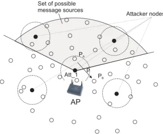
AP
Att_1 PA PB Attacker nodes Set of possible message sources pFigure 3: An example of a scenario in which an at-tacker nodeAtt 1observes a packetpbeing sent from
PAtoPB. The shaded area represents the attacker’s
estimation of the region from which the packet p
could have originated.
carry the same message. Another simple attack is if an at-tacker sends a message to some destinationD and tries to track the message to establish whereDis located. This at-tack is, however, very ineffective as the messages go through a set of nodes typically not controlled by the attacker and through access points which act as message mixes thus by minimize the chance ofD’s location being detected.
6.2
Anonymity
Here, we analyze the level of source and destination anonymity achieved by our scheme. For this, we will use an anonymity metric based on entropy proposed in [33] and [21]. LetX be a discrete random variable with probability functionpi =P r(X =i), whereirepresents each possible value thatX may take. In our case, eachicorresponds to an element of the anonymity set (a node). We denote by H(X) the entropy of the system after the attack has taken place. For each node belonging to the node set of sizeN, an attacker assigns a probability pi. H(X) can be calculated as: H(X) =− N i=1 pilog2pi
Thus the maximum entropy of the system equals to: Hmax= log2N
whereN is the size of the anonymity set. Based on this, we compute thedegree of anonymity dprovided by the system as:
d= H(X) Hmax
The degree of anonymity quantifies the amount of informa-tion the system is leaking. A system in which a user or a small group of users appear to be message originators or destinations, does not provide a high degree of anonymity.
0 0.1 0.2 0.3 0.4 0.5 0.6 0.7 0.8 0.9 1 0 2 4 6 8 10
number of nodes controlled by an Attacker-C-M
degr ee of anony m it y (d ) s=10, Attacker-0-M s=10, Attacker-C-0 s=80, Attacker-0-M s=80, Attacker-C-0
Figure 4: Pseudonym anonymity degree with Attacker-0-M and Attacker-C-0, for a control area with 80 nodes and for two sizes of the set of possible sources (s= 10 and s= 80).
Previously, we defined source/destination anonymity as the property that a particular message is not linkable to any source/destination, and vice-versa.
To analyze our privacy-preserving scheme, we observe two important aspects: (i) anonymity of node pseudonyms (i.e., linkability of the messages to node pseudonyms and their respective public keys) (ii) mutual linkability of node pseudonyms. These two aspects combined will give us a true degree of identifier anonymity.
We first observe the degree of pseudonym anonymity that our system provides. An Attacker-0-1 can observe the be-havior of its neighboring nodes and try to link the messages that they transmit to their pseudonyms. Thus, if Attacker-0-1 observes that a node PA(t) sent a message to PB(t), it can conclude the following: (i) PA(t) is either the mes-sage source, or a forwarding node (ii)PB(t) is not the mes-sage source (iii) other nodes in the attacker neighborhood P1(t), ..., Pk−1(t) which have not sent any messages in the recent past are probably not sources of the message. For simplicity, we denotep(X=PA(t)) bypA.
The attacker assigns to each pseudonym that it observes a probability that this pseudonym is the source of the message:
pA= 1 s pB= 0 p1=...=pk−1= 0 pi= 1−pA N−k−1
wheres≤Nis the number of sources (includingPA(t)) that might have sent the message given that it is forwarded by PA(t);kis the number of neighbors of the attacker (includ-ingPB(t)). The attacker can estimate this number based on the expected node (or even traffic) density in a given region. If PA(t) is located close to the access point, then almost any node in the control area is a potential source. IfPA(t) is located on the edge of the control area, then only a few nodes can be potential message sources. However,
Attacker-0-1 does not know which pseudonyms are potential sources, it can only estimate their number. Thus, the entropy of this system can be computed as
H(X) =1 slog2(s) + (1− 1 s) log2 s(N−k−1) s−1
If an attacker controls several malicious nodes (Attacker-0-M), each of the nodes it controls will provide information if the nodes in its neighborhood could be potential sources of the message. The entropy in this case is then
H(X) = 1 slog2(s ) + (1− 1 s) log2 s(N−M−1) s−1
where M is the number of neighbors of malicious nodes (typicallyM=M×k), ands≤sis the number of nodes in the set of possible sources that are not neighbors of the nodes controlled by the attacker.
In the case of Attacker-C-0, where the attacker controls a set of compromised nodes, the attacker can also exclude the nodes that it controls from the set of potential sources. Thus, for allC nodes under the attacker’s control, p(X = PAtt(t)) = 0, and the entropy can be computed as
H(X) = 1 slog2(s ) + (1− 1 s) log2 s(N−C−C−1) s−1
whereC is the number of neighbors of compromised nodes (typicallyC=C×k). The maximum entropy for Attacker-0-M and Attacker-C-0 differs, as the size of the anonymity set for the first attacker isN(as the attacker does not control any registered network nodes), whereas it isN−C for the second attacker (given that the attacker controlsCnetwork nodes). Thus, for Attacker-0-M,Hmax(X) = log2(N) and for Attacker-C-0Hmax(X) = log2(N−C). The size of the anonymity set in the case of Attacker-0-M remainsN even if the attacker knows that the set of possible sources s is smaller thenN. This is because even if the attacker knows the size of the set of possible sources, it does not know their pseudonyms, and thus any of the pseudonyms can be within the set of possible sources. The same is valid in the case of Attacker-C-0, except that here, the size of the anonymity set is diminished for the number of nodes that the Attacker controls, and for which it knows the pseudonyms and knows that they are not the message sources.
On Figure 4 we show the pseudonym anonymity degree with Attacker-0-M and Attacker-C-0, for a control area with 80 nodes and for two sizes of the set of possible sources (s= 10 and s = 80), in the case where the attacker distributes the nodes uniformly over the network, and where each at-tacker node has the same number of neighbors (k = 6). As expected, as the set of possible sources gets smaller, and the number of attacker nodes increases, the pseudonym anonymity degree decreases. It is interesting to observe that the anonymity of the system does not decrease significantly with the reduction in size s of the set of possible sources. This is because even if the attacker knows the size of this set, it does not know which pseudonyms belong to the set, and thus any pseudonym has an equal chance of being in the set. Only if the attacker controls a larger number of nodes, pseudonym anonymity decreases significantly.
These results demonstrate the effectiveness of our scheme, as
they show that our scheme prevents an attacker that controls a smaller number of nodes to jeopardize node anonymity. To link node pseudonyms to messages, an attacker thus needs to control a large number of nodes, and furthermore needs to be able to distinguish which packets carry the same messages. If we would assume that an attacker has information about network topology, the pseudonym anonymity would be sig-nificantly smaller. This is because the size of the anonymity set would be reduced from N to s (for Attacker-0-M) and to s−C (for Attacker-C-0). Here, C is the number of attacker nodes that are located within the region of possible sources.
Pseudonym anonymity is not sufficient to quantify the de-gree of node/user anonymity in the system. Even if an at-tacker can link messages to node pseudonyms, as the pseudonyms are changing, it is difficult for the attacker to distinguish which messages were generated by the same en-tity, or better, which pseudonyms belong to the same node. Attackers can try to mutually link node pseudonyms in two obvious ways: by observing the S/N ratio of the devices and by observing their signal watermarks.
The first attack is simple to mount, but effective only in some situations. It consists in the following: an attacker observes S/N ratio of the signals of the nodes in its neigh-borhood. If the attacker detects the same the S/N ratio for two pseudonyms which are used one after another, the at-tacker can conclude that the two pseudonyms are used by the same node. However, this attack can be performed by the attacker only during a short period of time, as long as the node does not move. If the observed node moves, the attacker cannot correlate anymore the pseudonyms that it used while it was still with any other pseudonyms that it generates in the future.
The second attack is more powerful, but requires higher at-tacker sophistication. This attack is performed such that the attacker detects signal watermarks of a network node, and links them with node pseudonyms. Whenever a node changes its pseudonym, and the signal has the same finger-print, the attacker can assume that the previously observed and the current pseudonyms are used by the same device.
6.3
Location Privacy
Both S/N and fingerprinting attacks aim at linking node pseudonyms, but also at tracking node locations. This is because the attacker nodes know their own current loca-tions and know which pseudonyms appear in their neigh-borhood. What they need to complete the picture about node movements is to link node pseudonyms. The finger-printing attack aims at doing exactly that. However, the fingerprinting attack has its limitations as well. One of the most obvious is that in order to track nodes effectively, the attacker needs to have many nodes installed all over the con-trol area. However, this attack can be effectively countered by implementing radio transmitters that can randomize fin-gerprints. Nevertheless, if appropriate protection against this attack is not applied, this attack can be very effective. If we exclude the possibility of fingerprinting attacks, node tracking becomes very difficult for the attacker, but not
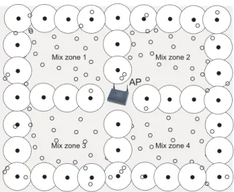
im-Mix zone 1 Mix zone 2
Mix zone 3 Mix zone 4
AP
Figure 5: An example of a scenario in which the attacker divides the access point control area into four mix zones of equal size.
possible. By installing a large number of nodes accross the access point control area, the attacker can track pseudonyms and correlate them by their locations. To illustrate this, it is sufficient to assume that the attacker has all the informa-tion about the past locainforma-tions of node pseudonyms. Then, given that the users do not move in an unpredictable man-ner, an attacker can manage to correlate node pseudonyms and thus jeopardize users’ location privacy. Thus, even if nodes change their pseudonyms very frequently, it does not increase the level of their privacy because they cannot change their locations at the same pace as they change their pseudonyms. As the nodes are being tracked, their loca-tions will be sufficient for the attacker to conclude which pseudonyms are used by the same node. This means that an attacker that can monitor pseudonym locations at all times, has a high chance of tracking all network nodes. Note that to perform efficient pseudonym tracking, the attacker needs to precisely locate network nodes. For this, the attacker can use triangulization-based methods (for which at least three attacker nodes are needed to locate the pseudonym), or location fingerprinting (for which the attacker needs to perform detailed measurements of the access point control area). Besides the imprecisions introduced by the location algorithms, the attacker also needs to cope with an incom-plete information about pseudonym locations. Therefore, it would be too pessimistic to assume that the attacker has a complete information on pseudonym locations. Instead, we will assume a more realistic scenario in which the attacker has only partial knowledge on pseudonym locations; namely we assume that the attacker can observes pseudonym lo-cations only within some specific regions controlled by the attacker.
This problem was already observed in [3] by Beresford and Stajano. In their work, these authors define a term mix zone. A mix zone for a group of users is a connected spa-tial region of maximum size in which none of the users has registered any application callback. This means that a node, while in a mix zone, does not register its location
0 1 2 3 4 5 6 7 0 20 40 60 80 100 120 number of attacker nodes (Attacker-0-M)
m a x im u m ent ropy H max MixSize=40 (2 mix zones) MixSize=20 (4 mix zones) MixSize=10 (8 mix zones) MixSize=5 (16 mix zones) MixSize=3
(26 mix zones) MixSize=2
(40 mix zones)
Figure 6: Maximum entropy as a function of the number of attacker nodes. The attacker divides the access point control area into sub-areas (smaller mix zones). The size of the mix zones determine the level of the system entropy.
with any authority. Thus, while in its mix zone, a node can change its identifier, so that it appears as a different entity when it leaves the zone. This scheme works only if there is a sufficient number of other users in the same mix zone (anonymity set) which guarantees a low probability of node’s pseudonyms (the pseudonym that it uses before it enters a zone and the one that it uses when it leaves the zone) being correlated. In our scenario, mix zones can be defined in the following way: a mix zone for a set of nodes is a connected spatial region of a maximum size in which none of the nodes is in the power range of any of the nodes controlled by the attacker. This is illustrated in Figure 5. In this example, the attacker divided the access point control area into four mix zones thus by reducing the entropy of the system. Namely, if the attacker subdivides the control area, it will reduce the number of pseudonyms that can be cor-related, as it knows which pseudonyms entered which zone, and which pseudonyms have left the zone. Thus, for each pair of pseudonymsPX(t1) andPY(t2), the probability that X = Y (that both pseudonyms originated from the same node) can be computed as:
P r(PX(t1), PY(t2) :X =Y) = 1/M ixSize
wherePX(t1) is the pseudonym observed by the attacker en-tering a mix zone at time t1, andPY(t2) is the pseudonym observed by the attacker leaving the zone at timet2 > t1, andM ixSizeis the number of nodes in the mix zone. The maximum entropy of each of the mix zones is determined by the number of nodes in that zone. Thus, if the attacker divides the access point control area into smaller mix zones (Figure 5), the entropy drops and it is easier for the attacker to correlate pseudonyms. On Figure 6 we show the maxi-mum entropy as a function of the number of attacker nodes. Here, the more nodes that the attacker controls, the sizes of the mix zones become smaller and their number increases; hence, the entropy of the system decreases.