Naveen Sharma
Sanjiv Kumar Gupta
System Software Group
HCL Technologies Ltd
Noida, India–201301
{naveens, sanjivg}@noida.hcltech.com
Abstract
Several microprocessors, used in digital signal processing and embedded devices, have lim-ited displacement (4-6 bit) in “register + off-set” addressing mode. In some cases, only auto increment/decrement addressing modes are available. Hence, while accessing data on local frame, there are number of explicit in-structions whose sole purpose is to reach the desired data. This paper describes the impact of layout of local variables on performance and code size for these architectures. It also de-scribes the techniques for optimal assignments of stack offsets such that instructions for ad-dress arithmetic for access of local variables are minimized. The implementation of the techniques in GCC is also discussed. Results indicate an improvement of 2%-7% in code size and 5-9% improvement in execution tim-ings for several benchmarks.
1
Introduction
The use of micro-processors in embedded de-vices has been growing. The complexity of applications that run on these processors has increased proportionately. This makes the use of HLLs such as C/C++ almost inevitable for writing these applications. Therefore, the com-piler has to address the special architectural is-sues normally found on these processors.
One prominent issue is the restrictive ad-dressing modes in these processors. Many of the architectures have limited offsets, if a ’reg+offset’ addressing mode is available or just the auto increment/decrement modes. Ac-cessing data beyond reachable offset incurs ex-tra instructions. While this cannot be avoided in all cases, local frame is one area where we can improve data layout to subsume the address arithmetic. This freedom can lead to subtle benefits both in terms of perfor-mance and code size. This flexibility is use-ful regardless of target; the benefits, however, are most apparenet for processors that have limited displacement capability (such as SH, ARM-Thumb, PA-RISC).
GCC currently does not allow to reorder items in local frame. The document first disccusses the problems that arise due to this. The solution strategy and the implementation are discussed subsequently.
2
Problem Description
The stack allocation scheme in GCC needs im-provements. In the present scheme, the objects are allocated on top of current frame when an allocation is required. An RTX of the of the form
(mem:mode (plus (fp) (const_int offset)))
is associated with it. A hard offset is thus as-signed to it at the very beginning. This scheme results in the following problems.
• Increased code size
• Alignment holes and thus larger runtime frames.
• Performace degradation due to cache thrashing for certain applications.
We first explain the impact of frame layout on code size, taking the example of SH architec-ture. The SH architecture has a limitation of four bit offset in the ’offset + register’ address-ing mode (@(k, rm)). The 4-bit offset is zero extended and multiplied by 1, 2 or 4, ac-cording to the operand size (being a byte, word or long). Hence a maximum of 64 bytes can be accessed from a base register using this ad-dressing mode. In cases where higher offsets need to be accessed, the compiler adjusts the registerrm, so that a given reference lies within desired displacement. Hence if we want to ac-cess location, say, (72, fp) on SH, the assember output looks like:
mov fp , r1 !Extra register add #72, r1 !Addition
mov.l @r1, r2 !Actual Load
Notice the worst case costs involved when accessing data beyond addressable offsets in frame.
• The cost to spill the registers for temporary stack base pointer of ar-ray/structure/class (spillreg).
• The cost to copy the frame pointer. (fpcopy).
• The cost to add the offset to temporary base pointer (regadd).
• The cost to restore the temporary base pointer after use (regrestore).
For floating point data SH allows pre-decrement, post-increment and indexed ad-dressing modes (r0being the sole legal index register). Similar problems are imminent there too.
As another example, consider this piece of code in which a large array is placed at begin-ning of the frame.
void func(void) { float foo[16]; int l,m,n; putval(&l,&m,&n); l=m+n; func1(l,m,n); }
GCC produces this code for statementl=m+n for SH, when we don’t reorder anything on frame.
mov r14,r1 !frame pointer r14 --> r1 add #68,r1 !reaching "m"
mov.l @r1+,r5 !m --> r5 and reaching "n" mov.l @r1,r6 !n --> r6
mov r5,r4 !m --> l
add r6,r4 !m+n -->r4 (stored to "l")
Note that frame layout is "foo, l, m, n"; so offsets assigned to these relative to the frame pointer are 0, 64, 68 and 72 respectively. Ideally, if stack was laid out differently with following layout "l, m, n, foo", GCC generates the following code.
mov.l @(4,r14),r5 ! m --> r5 mov.l @(8,r14),r5 ! n --> r6 mov r5,r4 ! m --> r4 add r6,r4 ! n+r4 --> r4
Notice the benefits by this simple reordering. First, a decrease in Code Size beacuse nbe-causef instructions, whose sole purpose is to reach data in local frame, are reduced. Sec-ondly Register "r1" in above example remains free to be utilized elsewhere. Thirdly reduc-tion in frame size in the general case because ordered layout will lead to lesser alignment holes. In cases when a large array on local frame is unused, we can significant stack space if we do not allocate it at all. (Array foo in the above example).
Last, if compiler allows frame object to be placed flexibly, the cache performance of ap-plications might also be improved.
We propose two improvements in way GCC al-locates local objects. The first improvement is the way the stack slots are represented inter-nally and secondly the algorithms to assign ac-tual offsets to address these problems.
3
Approach to the problem
The problem of offset assignments can be viewed in different ways. We can view this problem as similar to register allocation. Drawing analogy from the fact that compiler generates IL 1 code assuming infinite regis-ters and allocates actual hard regisregis-ters later, we can generate IL assuming infinite displace-ment and later map it to machine dependent displacement. While this mapping takes place we try to assign frame items within “fast ac-cess window” based on the interference graph of stack slots.[Burlin] describes a technique on lines of graph coloring. However, the approach has some implementation problems. Register allocation has significant differences with off-set assignment inspite of apparent sin spiteties. Some obvious differences that need to be taken care are
1IL:Intermediate language or RTL in case of GCC
• Size of frame items is variable unlike reg-isters which are of fixed size.
• Spilling has a different meaning than in traditional allocation.
• Graph coloring usually performs better for register sets numbering more than 16. While considering limited displacements, the algorithm seemed expensive.
These and several others problems are de-scribed by [Burlin].
The most popular approach for offset assign-ment is described by [Liao]. This approach is described for auto increment/decrement modes and can be adjusted to accomodate limited dis-placemenaccommodates occurence of adjacent accesses asoccurrenceto frame layout.
3.1 Solution Strategy
3.1.1 The stack pseudos
It was obvious that current representation of stack slots had several problems. It made reshuffling objects in the stack virtually impos-sible. An rtx of the form
(mem:mode (reg/f/c:Pmode slot))
is taken as the representation of a frame object. The slot is a stack address(or a stack pseudo). It is similar to virtual register but with slightly different semantics. We return a rtx of this form for each requested stack slot. Note that the special flag /c is used to tell that this is stack address pseudo. The register allocator should not try to allocate any hard reg for this because it is already a known stack slot.After register allocation, we sort the allocated stack slots by size and number of references and con-vert it to normalfp+offsetform.
3.1.2 The Access Graph
An access graph is derived from a basic block. It gives the relative benefits of assigining adja-cent locations for assigningof local variables. Given a insn sequence, an access sequence can be defined from it. Given an opera-tionset(r3 op (r1 r2)), the access se-quence is r1, r2, r3. The access sese-quence for an ordered set of operations is just a concate-nated sequence of each individual operation. The access graph G(V, E) is derived from ac-cess sequence by adding edges corresponding to adjacent access between variables. Instead of an adjacent access, we take the limited off-set window to add the edges. For each repeated adjacent access, update the weight associated with an edge. At the end, we have a possi-bly disjoint graph, representative of benefits of placing variables within a same displacement window.
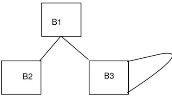
This access graph can be extended to model the entire procedure with the help of data flow in-formation.. The access graphs of basic blocks have to merge. Let us consider the scenario shown in Figure 1. Assume that probability of execution of basic blocks B2 and B3 is p2, p3 respectively. Further, since B3 is in a loop let us assume it has frequency of executionf. Then the following heuristics apply.
1. For access sequences in B3, the weight as-signed while connecting adjacent variable accesses is proportional tof.
2. Weights assigned while connecting stack variable accesses between B1, B2 and B3 is proportional to probabilities p2 and p3. These heuristics ensure that access graph takes into account the locality of accesses across en-tire procedure. From this information, we can determine placement of variables on the stack to minimize large displacements.
3.1.3 Use Data Flow Information
Another strategy is to use information built by flow analysis pass of the compiler. GCC builds data flow information regarding pseudo regis-ters. This includes the attribute REG_FREQ which is the estimated frequency of the refer-ence of the pseudo. Since stack slots are no diferent, this information is generated for dif-ferent can use this information for frame lay-out by placing most frequently referenced vari-ables near the frame.We tried the following heuristics:
1. sort the stack slots by size first
2. place the most frequently referenced vari-ables together near the frame
3.1.4 Stack Reorganization Pass
A stack reorganization optimization pass is in-troduced after register allocation and is called as a subroutine during the reload phase2. This
new pass primarily takes care of stack lay-out of variables. Stack assignments are made for pseudo registers based on locality of us-age.It was observed that stack reorganization will have little effect before reload because most of the stack allocations are from within reload. So next possibility was to place it af-ter reload pass. But replacing stack pseudos with their normal form after reload turns out to be complicated because validation of changed rtx’s becomes part of stack reorganization, a task that reload is already doing. So calling stack reorganization from within reload turns out out be simpler and reload’s code need not be repeated.
The algorithm is based on method given by [Liao]. The algorithm starts with the insn chain
of the function being compiled. The routine Construct_Access_Graph converts into a graph G(V, E) where V is number of variable accesses in a basic block and E is number of edges. An edge will exist between two variables v1 and v2 if they are accessed adjacently and the fre-quency of the adjacent access is recorded in the edge. Then algorithm uses a greedy approach, where it tries to add the edges with maximum weight adjacent to each other in spanning tree E’. The routine Traverse_And_Assign_Offsets takes this spanning tree as input and assigns offsets to variables in stack.
INPUT: The insn chain of the function. OUTPUT: Offset Assignment on the Stack.
G (V, E)<-- Construct_Access_Graph (L); /* G is a graph with local variables
(V) as nodes and E is the number of edges. */
Es: sorted list of edges in descending order of weight.
/* The weight of an edge between <v1, v2> is frequency/relative gain of their adjacent access. */
G’(V’, E’): V’<--V, E’<--NULL;
while (|E’| < |V| -1 && Es != NULL) {
/* Choose first edge. */ e = Es[1];
/* Remove it from Edge List */ Es = Es - e;
if ((e does not cause a cycle in G’) &&(e does not cause and node in V’ to have degree > 2)
add e to E’; else
reject e; }
/* Now the best disjoint path cover is available. */
Traverse_And_Assign_Offsets(E’)
3.2 Benchmark Results
The performance improvement by frame re-ordering depends on the following factors.
1. Size of the local frame.
B1
B2 B3
Figure 1: A sample control flow
2. Number of accesses of variables moved near the frame.
3. Frame layout heuristics.
In the best cases, the execution perfromace could go as high as 9%. The results for SH4 processor are shown here. The base version used for benchmark measurements GCC-3.3. The compiler options are ’-O2 -ml m4’. A new option namely -fstack-reorg is in-troduced to enable stack reorganization. Ta-ble 1 gives size comparisons of stress1.17 files with and without stack reorganization. The Heuristics used are while frame layout are those of section 3.1.3. It is clear that in most cases, we have a decrease in code size. Some benchmarks show slight code size increase due to noise in reload phase.
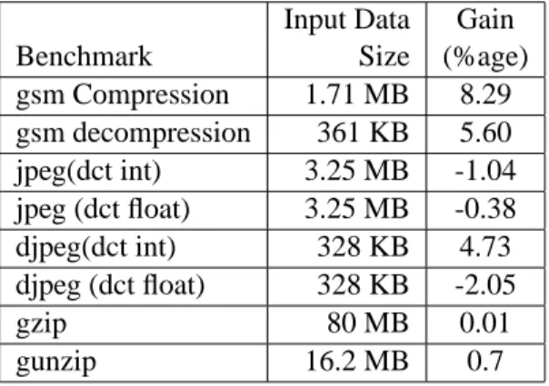
The execution results for some benchmarks are shown in Table 2. Only those benchmark which have variation in execution timings are shown. One undesirable side effect, which is probably the main cause of performance degra-dation, is the harm done to loop optimizer be-cause stack addresses are not exposed to it. A loop optimization pass after reload phase could possibly fix this problem.
File size decrease Name size (stack-reorg) (%) revolt.o 5956 5508 7.52 l3psy.o 15024 13968 7.03 mission.o 16972 15820 6.79 blocksort.o 4960 4640 6.45 advdomestic.o 8152 7640 6.28 explode.o 7916 7468 5.66 advmilitary.o 14844 14140 4.74 dogmove.o 10436 9956 4.60 lndsub.o 13820 13276 3.94 compress.o 4968 4776 3.86 physics.o 9020 8700 3.55 jidctflt.o 928 896 3.45 navion_gear.o 2040 1976 3.14 mhitm.o 22528 21824 3.13 r_segs.o 4384 4416 -0.73 q_shared.o 7966 8030 -0.80 g_phys.o 7396 7460 -0.87 tonal.o 10832 10928 -0.89 regex.o 24012 24268 -1.07
Table 1: Code Size Comparisons
Input Data Gain
Benchmark Size (%age)
gsm Compression 1.71 MB 8.29 gsm decompression 361 KB 5.60 jpeg(dct int) 3.25 MB -1.04 jpeg (dct float) 3.25 MB -0.38 djpeg(dct int) 328 KB 4.73 djpeg (dct float) 328 KB -2.05 gzip 80 MB 0.01 gunzip 16.2 MB 0.7
Table 2: Execution Timings
4
Acknowledgements
We would like to thank the GCC developer community for help. Their support is in-valuable. We specially thank Zack Weinberg, Toshiyasu Morita, and Joern Rennecke for im-plementation ideas and comments.
References
[Liao] S.Liao and S.Devdas Storage
Assign-ment to Decrease Code Size, MIT
De-partmenet of EECS, Cambridge MA (1995).
[Burlin] Johny Burlin Optimizing Stack Frame
Layout for Embedded Systems,
Informa-tion Technology Computing size depart-ment, Uppsala University, Sweden. [GCC] GCC Internals Manual