A Tablet Based Immersive
Architectural Design Tool
Ross Tredinnick Lee Anderson Brian Ries Victoria Interrante University of Minnesota D’Nardo Colucci, Ph.D
The Elumenati, llc, Minneapolis, MN Abstract
In this paper we describe a SketchUp VR system in which we create a hybrid two-dimensional / three-dimensional immersive architectural design system. This system combines a tablet PC, an optically tracked room, a display wall, a SpaceTraveler motion controller, and stereographic eyewear to allow immersive conceptual design and walkthrough using a version of SketchUp that has been enhanced with Ruby plug-ins. The tablet PC provides a ”sketchpad” type of user interface for SketchUp, while the tracked space and display wall enable the designer simultaneously to design at full (or any other) scale in an immersive (VR) environment.
Introduction
Traditional D modeling applications provide a screen-based paradigm,
whereby an architectural model exists
within a window on a flat display screen.
More recently, advancements in virtual environment technology have triggered the emergence of a new paradigm, known as immersive architectural design (Anderson 00). Immersive architectural design programs utilize virtual reality hardware, such as a HMD, to place the designer’s viewpoint inside of the model. Geometry creation and manipulation takes place by way of a three-dimensional input device.
Both traditional and immersive design paradigms have their advantages and disadvantages that will be discussed prior to describing our hybrid system.
A typical modeling application includes viewing tools that facilitate designing at a wide range of scales. To place new geometry in the environment at a distant location from the current viewpoint, a camera pan tool quickly shifts the center of design to the necessary location. On the other hand, designers can modify tiny details of an intricate model by zooming in and focusing the center of design on small areas of a model.
Despite this practical functionality for changing views, some downfalls exist for the desktop design paradigm. The designer using a modeling application is performing a highly integrative act, attempting to create an environment with a strong physical three-dimensional presence. Designing with the inherently two-dimensional desktop interface, limits the design process. Modeling applications effectively limit the viewing angle and provide only limited screen resolution, which tends to objectify the design space, leading to a focus on external form rather than inhabitable space. The design may be also be negatively affected by the display screen, with and its strong vertical and
horizontal edges and fixed aspect ratio.
The emergence of virtual reality technology introduced a new possibility for architectural design. Immersive architectural design places the designer within the environment of the model, giving a realistic sense of scale and presence. This design method has the potential for overcoming several of the negative aspects of the desktop paradigm. For example, a dynamically changing
viewpoint exists, often with stereo viewing, which leads to a greater sensation of presence of the inhabitable space being designed. Although immersive modeling
may seem more beneficial than traditional
desktop based programs, problems
emerge here as well. First of all, navigation becomes more of an issue. Placing new geometry in the model at a distant location from the current focus requires an intuitive, easy form of navigation. Also,
the modification of small details may
require additional viewing tools to zoom in on locations, which may feel unintuitive within a head mounted display. Small detail
changes requiring precise movements
may be difficult with a three-dimensional
input device. Finally, a three-dimensional user interface must be considered to avoid awkwardly re-introducing a two-dimensional user interface into a supposed three-dimensional environment.
In this paper, we introduce SketchUp VR, which attempts to combine the better features of the screen-based and virtual-based design paradigms. The system joins several pieces of virtual environment hardware together with a tablet PC to create a hybrid system for design. We build the software system upon the popular SketchUp modeling application. SketchUp contains a built-in Ruby application programming interface, which we use to extend SketchUp to be an immersive design application. The user employs SketchUp on a tablet PC to create designs, while simultaneously being immersed in virtual environment. All changes to the SketchUp model are simultaneously changed in the virtual environment. Related Work
Advancements of virtual environment technology triggered a change in the way we can interact with a software program. Virtual environment researchers adhere to this important idea everyday by designing systems that allow three-dimensional immersive interaction. Architectural design has become a very popular area in terms of immersive technologies and many immersive modeling systems have been designed and tested (Butterworth 99), (Donath and Regenbrecht 996), (Mine 997a), (Mine et al. 997b), (Forsberg et al. 998), (Donath et al. 999), (Hill et al. 999), (Regenbrecht et al. 000),
(Dave 2001), (Anderson et al. 2003). In addition, much research has gone into understanding how digital technology
advancements can benefit the conceptual design stage in architecture (Campbell and
Wells 1994), (Bowman 1996), (Bridges and Charitos 1997), (Bowman et al. 1998), (Kukimoto et al. 1999), (Lau and Maher 2000), (Schnable et al. 2001), (de Vries et al. 2001), (Schnable 2002).
There has been a fair amount of literature about combining the
two-dimensional design metaphor into the
three-dimensional virtual environment.
The majority of previous work done in this area combines a tracked clipboard or drawing pad with a tracked pen stylus.
The 3Draw system introduced such a user interface (Sachs et al. 1991). Their system allowed three-dimensional sketching
of splines to model objects. Unlike our
system, their work was not immersive,
and interaction occurred through a plain desktop monitor. Since then, various
systems have combined a tracked
clipboard and pen within a head mounted display environment (Angus and Sowizral
1995), (Bowman et al. 1998), (Schmalsteig et al. 1999), (Chen et al. 2004). Our work differs from this work in two main
respects: first of all, our system runs on a projection-based display rather than a head mounted or workbench display; and
secondly, interaction occurs through an actual tablet PC running windows and
SketchUp rather than a tracked clipboard. Another piece of significant work that has
some commonalities with our system is the worlds in miniature system (Stoakley et al. 1995). Like their system, our
tablet PC contains a de-coupled camera viewpoint from the display wall and
manipulation of objects may occur through
SketchUp. Unlike their system and also like previous differences, our work renders through a projection-based display rather than a head mounted display.
The Hardware System
Our hybrid system combines several
pieces of virtual environment technology
to create an immersive design area.
The total system consists of an optical tracking system, a curved display wall,
three PCs, one tablet PC, a 3D Connexion
SpaceTraveler, and Crystal Eyes 3D stereo
glasses, two stereo emitters. I will discuss
how each feature fits into the system
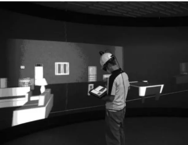
below. The system is shown in action in
figure 1.
Tracking System
The room that holds our project contains a Hi-Ball 3000 wide area optical
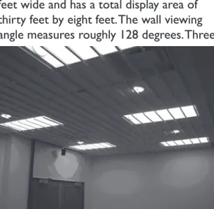
tracker (Welsh et al. 1999). We mount the ceiling of our room with several infrared
light emitting diode strips that allow a HiBall sensor to calculate position and
orientation. The total amount of tracked
space roughly measures thirty feet by twenty four feet. The system provides
Figure 1. A student works on an apartment model using the system.
updates to a Hi-Ball sensor at a rate of 500-800 Hz. We mount a Hi-Ball sensor on top of a basic white construction helmet that the designer wears. The tracking system provides position and orientation information for our software system and dynamically updates the layout of the virtual scene based on current position and view direction toward the screen. The HiBall sensor transmits information over wire to a CIB box that knows the layout of the system on the ceiling and converts the data to a point that represents position and a quaternion that represents orientation. To transfer tracking data between the CIB and our software system, we interface with the VRPN software library (Taylor II et al, 00). Figure two shows a picture containing a portion of the tracking system.
Display Wall
The room contains a curved display wall, back projected by three Christie Mirage 000 stereoscopic projectors. The wall measures eight feet tall by twenty four feet wide and has a total display area of thirty feet by eight feet. The wall viewing angle measures roughly 8 degrees. Three
AMD Athlon 6 X Dual Core 800+ PCs with gigabyte of RAM compliment the three projectors. Each PC holds a NVidia Quadro FX 500 graphics card with 5 MB of video memory. The graphics cards are supplemented with NVidia gSync cards to enable proper stereo viewing. Figure three shows the display wall. The display wall provides the immersive three-dimensional stereoscopic display of the architectural design system.
Tablet PC
We run the SketchUp program and our accompanying software on a Toshiba Portégé tablet PC. The tablet PC contains an Intel Pentium M .00 gigahertz processor with gigabyte of RAM. The user interfaces with the tablet PC by directly applying its accompanying pen stylus to the screen. The use of a tablet PC provides mobility within the immersive environment.
Spacetraveler
We optionally accompany the system with a D Connexion SpaceTraveler. The SpaceTraveler interfaces with the
Figure 2. A picture of the diode strips for the optical
display wall to provide three-dimensional navigation within the design environment. The SpaceTraveler connects to the tablet PC. Updates of position and orientation are sent to the display wall through the networking of our software system.
Stereo Glasses
We use CrystalEyes three-dimensional stereo shutter glasses and place two stereo emitters within range of the display wall. Combining this with stereo rendering
on the display wall gives a significant
three-dimensional presence while modeling using the tablet PC. The user is still able to view the tablet PC while wearing the stereo glasses because the screen on the tablet PC contains a plastic layer that re-polarizes the light. Without this plastic layer, the tablet PC screen would disappear while wearing the stereo shutter glasses. Software System
We have built a unique software system on top of the commercially available SketchUp design program. The software system contains three basic pieces: the SketchUp Ruby interface, the networking software written using basic windows sockets in C++, and a C++ OpenGL-based rendering engine of the SketchUp environment for the display wall. We describe the three portions of the software system in this section.
SketchUp Ruby API
Ruby is an interpreted scripting
language developed by Yukihiro Matsumoto for quick and easy object oriented
programming tasks. The SketchUp
Ruby API gives any designer access to most aspects of the SketchUp program through a collection of Ruby classes. Documentation for these classes
accompanies the SketchUp program. Ruby commands may be issued by way of a simple Ruby input console in SketchUp. For example, a user can modify the default front color of a face by typing the following command into the Ruby console: Sketchup.active_model.rendering_options [“FaceFrontColor”] = Color.new (55, 0, 0). In addition to changing rendering details, the Ruby API contains classes for
building unique tools, creating fly-through
animations, and adding new user interface buttons and menus for custom purposes.
One critical factor in the SketchUp Ruby API that allows the extension of SketchUp to a virtual environment is its built-in animation class. The animation class acts as a template to allow a background loop to run within the SketchUp design environment. A user may run an animation within the SketchUp environment by creating a Ruby class that contains the necessary nextFrame method of the Ruby API. The nextFrame method would then modify the viewpoint of the camera over some period of time. In our implementation, we ignore modifying the viewpoint and instead make use of the animation loop in a different manner.
A second important feature of the SketchUp Ruby API intrinsic to our system is the attribute dictionary class. An attribute dictionary is a collection of arbitrary features that attach to a SketchUp entity. An entity is the term SketchUp adopts for a piece of geometry, such as a face or edge. An attribute dictionary acts as a basic hash table, therefore allowing both fast assignment
and retrieval of extra information about a piece of geometry. Attribute dictionaries greatly extend the functionality of the SketchUp design program. For example, suppose extra information concerning cost and manufacturing date need to be retained for a group of building components. Each extra piece of
information could be read into an attribute dictionary and displayed in a report
detailing that information in the current SketchUp model.
We have written a Ruby script that incorporates these two features of the SketchUp Ruby API. The script acts as an updating loop for controlling when and what information is sent across our network. The script runs a background loop in SketchUp and maintains various attributes about the current geometry within a SketchUp model. On each frame, the script loops through all current entities of the model, checking to see whether the entity has been sent across our network. If we have not sent the entity across the network yet, we transmit a message containing geometrical and material data about the entity. If we had previously sent the entity across the network, our program checks to see if either an entity’s visual attribute or physical location has changed within the model. If so, we re-send a message across the network containing updated information about the entity. Upon running the program, and before beginning our updating loop, we write out
a basic text file containing initial model
data to a network folder so that the three
PCs controlling the wall can parse the file
and prepare to render the initial scene. This pre-process creates an initial scene on the wall faster than if we were to send all data over the network.
The Network
In order to transfer SketchUp data to the PCs controlling the display wall, we wrote our own networking software to transfer the entity information from the tablet PC to the three PCs controlling the wall projectors. We implement a basic client server model to achieve proper transmission of data. In our model, the tablet PC acts as a server and communicates with a total of four clients, itself, and the three PCs running the wall. The tablet PC must communicate with itself in order to obtain SketchUp information. At the time of this paper, although the Ruby scripting language has a useful networking class, the class is unable to load within the SketchUp Ruby API context. To work around this, we adopted a built-in SKSocket module provided with the SketchUp software. The module provides very basic socket communication, only allowing communication through a single socket at a time. This eliminated our proposed option of communicating from the Ruby API directly to the three wall PCs. We therefore have the SketchUp Ruby script send data to a C++ networking program that simultaneously executes on the tablet PC, so that the information can be queued and forwarded to the three PCs controlling the display wall.
To transfer entity information we have developed a simple, yet effective, message system that allows variable length packets of data to be sent across the network. We create a method to pack data into a character string for each entity type in
SketchUp. The string contains first, a single
character signifying the type of entity, followed by material and physical location
data. On each frame we store all current updates in an array and, after checking all current entities, create a packet containing the total length of the updates followed by a string containing all of the new information. The tablet PC forwards the packet to the three PCs that parse the data and update the rendering context.
Rendering
The final portion of our software
system retrieves SketchUp data from the network and re-displays it on the curved display wall. The SketchUp design program contains a sketchy, non-photorealistic display style to emphasize the program as a conceptual stage design tool. We have mimicked their rendering style as closely as possible to maintain equivalent visual information between the tablet PC and the wall. We implement the system in C++ via the OpenGL graphics library for rendering and via the Win API for windowing. The rendering consists of two sided lighting, texturing, basic triangular polygons, and lines for highlighting edges of objects, which add to the non-photorealistic feel of the program. We have the ability to render our scenes with stereo viewing for increased three-dimensional realism and presence.
We implement a hierarchical display list system in order to render the various entities of the SketchUp program.
The SketchUp entity system contains three basic primitives: faces, edges, and component instances. A component instance is a group of edges, faces, and possibly other nested component instances. Component instances are
saved in separate files from the current
SketchUp model. They serve as miniature
models that designers can insert into their model from a built-in component browser. All entities within the SketchUp
program possess a unique identifier called
an entityID whose value may be accessed through the Ruby API. The entityID is included in messages we send across the network and provides a convenient key for a hash table that we maintain to display objects. After a wall PC retrieves a SketchUp message from the network, we store its data and generate a single display list, if the entity is a face or edge. If the entity is a component instance, we generate a hierarchical display list. The hierarchy resembles a tree whereby the root represents the outer most parent component, each inner node represents a nested component, and each leaf of the tree is a collection of faces and edges. Each inner node compiles its own display list whose call is then compiled into the display list of the root component. The display list structure of our rendering system allows for fast rendering speeds, and smooth interaction between SketchUp entities on the tablet PC and corresponding data on the display wall.
To accurately render the SketchUp data on the curved wall surface, we borrowed previously used techniques
for rendering to curved display surfaces;
however, unlike this earlier work, our techniques do not calibrate the screen with cameras (van Baar et al 00). Instead, we generate a mesh representing the screen using our optical tracking system. We mount a HiBall 00 sensor onto a HiBall stylus and augment the stylus with a metal pointing rod. We click points on aligned grids displayed by the three projectors to record points in tracker space. With the tracker space
input points, we generate splines to approximate the surface shape of the screen. We then projectively texture the scene onto the approximated mesh using graphics hardware. We render a seamless image by using three different viewing frustums whose parameters depend on the person’s currently tracked position and view direction toward the screen. We are working on improving the blending at the boundaries of the projected images. A summary diagram of the whole system is
shown below in figure four
System Features
By combining a tablet PC based display with an immersive display wall, we have formed a virtual environment system with several unique features. The following sections will discuss each of these features in turn.
Retaining SketchUp Tools By building a system on top of a popular, commercially available software product, we retain the convenient design tools inherent to the SketchUp program
De-coupled Viewing
The system de-couples the camera viewpoint on the tablet PC from the viewpoint on the immersive display wall. This feature allows users to design on the tablet PC from a traditional desktop based viewpoint, while at the same time to become immersed in their creation through a viewpoint realistically positioned in the model. Designers can freely walk about a limited space of the environment by way of our tracking system. The
SpaceTraveler quickly transforms the position and orientation of the viewpoint on the display wall to navigate to a distant location. The viewpoint on the tablet PC can be separately orbited, panned,
zoomed or set to a specific location by
way of the various camera tools inherent to SketchUp. In this way, the tablet PC viewpoint can zoom in and manipulate small details on a SketchUp model, while users can critique the effects of the changes on the whole object by looking at the display wall. Executing minutely detailed changes in a regular immersive environment poses more challenges due to the need to manipulate overly sensitive three-dimensional input devices. An
example of the de-coupled viewpoints is
shown in figures five and six.
Scale
The SketchUp program also includes tools for accurately measuring distances and angles through a tape measure and a protractor tool. Additionally, SketchUp contains an inferencing system that
allows easy creation of specifically sized
geometric primitives in relation to other current primitives in the model. The
system snaps tools to specific points in
space such as the midpoint of an edge or a line perpendicular to the corner of a box. These two features easily allow the creation of designs to detailed scales. With a desktop-based program, such drawings still do not achieve a true sense of scale, since we view the model through a window on a small screen display. With our tracked display system, we have the ability to accurately create geometrical
objects of specific sizes on the tablet PC
Figure 4: A summary diagram of the Ruby updating loop, the networking and the layout of our display wall. The Ruby script runs on our tablet PC and messages are sent to its C++ networking code. The tablet PC forwards the messages onto the display PCs.
Figure 5. A screenshot of a SketchUp apartment model. Figure 6: The model displayed on our wall from an interior viewpoint.
on our wall display. This introduces an element whereby the designer can quickly critique various portions of a model at life-size scale directly after modeling it on the tablet PC.
Portability
As is, our system is not completely
portable; however, it is possible that the
SketchUpVR system could be constructed on a different virtual environment
hardware setup. Since our program communicates with our tracking system via VRPN, a publicly available program for obtaining tracking data over a variety of virtual reality tracking devices, the system could work with a multitude of trackers. The networking system could easily be
modified to communicate with a different
number of PCs. The part of our system that would potentially require the most
modification is the rendering system.
The rendering system would have to be changed to adhere to a different display setup. Nonetheless, with the proper software, the SketchUpVR system could
be displayed on a four, five, or six-sided
CAVE or any form of curved or dome projection-based display (Cruz-Neira et al, 99).
Conclusions / Future Work We have created a hybrid two-dimensional / three-two-dimensional tablet based design tool for immersive architectural design and walkthrough. The tool retains the advantages of desktop based CAD programs, as well as immersive architectural modeling programs. The system combines a high level object-oriented interpreted scripting
language, Ruby, with traditional C++ based, networking software and OpenGL rendering system. We utilize graphics hardware to projectively texture a SketchUp model onto the mesh acquired with our optical tracking system. Our curved wall provides an immersive stereoscopic display environment. The desktop portion of the system builds upon a popular commercially available CAD program and retains many of its valuable features. The tablet PC works well because it retains the pencil and paper-based architectural design metaphor and communicates over a local ethernet with the display PCs. SketchUp’s ability to insert a wide variety of component models could ease virtual environment creation for research or application purposes. The ability to port the system to a different virtual reality setup is not out of the question.
We have several possible additions and utilizations for the system. We plan to obtain a user study of the system to determine its effectiveness when compared to other forms of
three-dimensional immersive design. We also plan to incorporate the system for studying the effects of scale on conceptual design in architecture. We also plan to compare the effectiveness of our hybrid system to desktop and immersive d design alone. We plan to explore the possibility of adding different rendering styles to our re-creation of the SketchUp model. Improving graphics to achieve photorealistic quality or modifying the rendering for different non-photorealistic painterly styles may introduce different effects on the design process. Adding shadows to introduce an extra depth cue is also on the horizon. We also plan to implement a lighting system by
way of component models.
Now that we have a base networking system setup, we may explore the
possibilities of extending this to a collaborative design tool. By adding multiple tablet PCs designers could collaboratively create and simultaneously view SketchUp models in
three-dimensional stereo. We have recently added a sound system to our display wall and we may add sound to the software to enhance the sense of presence for research purposes. Another possible direction to explore with the system is to attach a tracker to the tablet PC itself, and update the view of the tablet PC based on user location in our tracked room; however, this would affect the ability to view the total scene on the tablet
PC. A final direction we would like to
explore is to substitute the SpaceTraveler with a different, perhaps smaller, three-dimensional navigation device that could possibly attach to the tablet PC. In the ideal situation, the system would be completely wireless. However, although wireless communication between the tablet PC and display PCs is something we hope to achieve soon, the tracking system and SpaceTraveler still would prevent the system from completely wireless operation.
References
Anderson, L. (1992). Virtual Graffti: Three-Dimensional Paint Tools for Conceptual Modeling in Upfront. Mission -Method - Madness [ACADIA Conference Proceedings / ISBN 1-880250-01-2], 127-133.
Anderson, L., J. Esser, and V. Interrante. (2003). A Virtual Environment for Conceptual Design in Architecture.
9thEurographics Workshop on Virtual
Environments / 7th International
Workshop on Immersive Projection Technology, 57-63.
Angus, I. and H. Sowizral (1995). Embedding the 2D interaction metaphor in a real 3D virtual environment. In Proceedings of SPIE, Stereoscopic Displays and Virtual Reality Systems. 2409: 282-293.
Bridges, A. and D. Charitos. (1997). On Architectural Design in Virtual Environments. Design Studies 18:143-154.
Butterworth, J., A. Davidson, S. Hench, and T. M. Olano. (1992). 3DM: A Three-dimensional Modeler Using a Head-Mounted Display. ACM Symposium on Interactive 3D Graphics, 135-138. Bowman, D. (1996). Conceptual design
space.beyond walkthrough to immersive design. In Designing Digital Space, ed. Bertol D., 225-236. Wiley: New York.
Bowman, D., L. Hodges, and J. Bolter. (1998). The Virtual Venue: User-Computer Interaction in Information-RichVirtual
Environments. Presence: Teleoperators and Virtual Environments 7(5): 478-493. Bowman, D., J. Wineman, L. Hodges, and
D. Allison. (1998). Designing Animal Habitats Within an Immersive VE. IEEE Computer Graphics & Applications 18(5): 9-13.
Campbell, D.A. and M. Wells. (1994). A Critique of Virtual Reality in the Architectural Design Process. University of Washington HITL Technical Report R-94-3, http://www.hitl.
Chen, J., D. Bowman, J. Lucas, and C. Wingrave. (2004). Interfaces for Cloning in Immersive Virtual Environments. Proceedings of the Eurographics Symposium on Virtual Environments, 91-98.
Cruz-Neira, C., D. J. Sandin, T. A. DeFanti, R. V. Kenyon, and J.C. Hart. (1992). The CAVE: AudioVisual Experience Automatic Virtual Environment. Communications of the ACM 35:67-72. Dave, B. (2001). Immersive Modelling
Environments, Reinventing the Discourse: How Digital Tools Help Bridge and Transform
Research, Education and Practice in Architecture. Proceedings of the 21st Annual Conference of ACADIA, ed. W Jabi, 242-247.
Donath, D., E. Kruijiff, and H. Regenbrecht. (1999). Spatial Knowledge
Implications During Design Review in Virtual Environments. ACADIA Conference Proceedings, 332-333. Donath, D., and H. Regenbrecht. (1996).
Using virtual reality aided design techniques for three-dimensional architectural sketching. Design Computation, Collaboration, Reasoning, Pedagogy. ACADIA Conference
Proceedings, 201-212.
Donath, D. and H. Regenbrecht. (1999). Using Immersive Virtual Reality Systems for Spatial Design in Architecture. AVOCAAD ‘99
Conference Proceedings, Brussels, 307-318.
de Vries, B., A. J. Jessurun, and J. J. van Wijk. (2001). Interactive 3D Modeling in the Inception Phase of Architectural Design. Eurographics Short
Presentations 4(7): 265-271.
Forsberg, A. S., J.J. LaViola Jr., and R.C. Zeleznik. (1998). ErgoDesk: A Framework for Two- and Three-Dimensional Interaction at the ActiveDesk. Proceedings of the 2nd International Immersive Projection Technology Workshop.
Hill, L.C., C. Chiu-Shui, and C. Cruz-Neira. (1999). Virtual Architectural Design Tool (VADeT). Proceedings of the 3rd International Immersive Projection Technology Workshop, 231-241. Kukimoto, N., K. Toizumi, S. Kitsuki, T.
Oda, and T. Iwasaki. (1999). Virtual Environment for Graphic Thinking for Architectural Design. Proceedings of the Virtual Reality Society of Japan, Second Annual Conference, 323-326. Lau, K. H. and M. L. Maher. (2000).
Architectural Design and Virtual Worlds. Architecture Week T7.1-T7.2. Mine, M. (1997). ISAAC: A Meta-CAD
System for Virtual Environments. Computer-Aided Design 29(8): 547-553. Mine, M., F. Brooks and C. Sequin.
(1997). Moving Objects in Space: Exploiting Proprioception in Virtual-Environment Interaction. Proceedings of ACM SIGGRAPH ‘97, 19-26.
Regenbrecht, H., E. Kruijff, D. Donath, H. Seichter, and J. Beetz. (2000). VRAM - A Virtual Reality Aided Modeller, Promise and Reality. eCAADe Conference Proceedings, 235-237. Schmalstieg, D., L. M. Encarnacao, and Z.
Szalavari. (1999). Using transparent props for interaction with the virtual table (color plate S. 232). In Proceedings of the Conference on the 1999 Symposium on Interactive 3D Graphics, ed. Stephen N. Spencer, 147-154. New York. ACM Press.
Schnabel, M. A. (2002). Collaborative Studio in a Virtual Environment. International Conference on Computers in Education, Massey, New Zealand.
Schnabel, M. A., T. Kvan, E. Kruijff, and D. Donath. (2001). The First Virtual Environment Design Studio. Proceedings of the 19th ECAADE - Education for Computer Aided Architectural Design in Europe Conference.
Stoakley, R., M., J. Conway, and R. Pausch. (1995). Virtual reality on a WIM: Interactive worlds in miniature. In Proceedings of ACM CHI ‘95 Conference on Human Factors in Computing
Systems, 265-272.
Taylor II, R.M., T. C. Hudson, A. Seeger, H. Weber, J. Juliano, and A. T. Helser. (2001). VRPN: a device-independent, network-transparent VR peripheral system. Proceedings of the ACM symposium on Virtual reality software and technology.
van Baar, J., T. Willwacher, S. Rao, and R. Raskar. (2003). Seamless
Multi-Projector Display on Curved Screens. Eurographics Workshop on Virtual Environments (EGVE), 281-286. Welch, G., G. Bishop, L. Vicci, S. Brumback,
K. Keller, and D. Colucci. (1999). The HiBall Tracker: high-performance wide-area tracking for virtual and augmented environments. Proceedings of the ACM symposium on Virtual reality software and technology, 1-ff.