JETIR1810732 Journal of Emerging Technologies and Innovative Research (JETIR) www.jetir.org 241
BLDC Motor Driven with Solar PV Array Fed Water
Pumping System Employing Zeta Converter for speed
control
Md Khalid, Prof. Tejaswita Katyayani M.Tech Student, Professor
Electrical& Electronics Department of Engineering Trinity Institute of Technology & Research, Bhopal, India
Abstract : The rising energy demand require coupled with the possibility of reduction in supply of non-renewable fuels, evidenced by petroleum crisis, along with increasing concerns about ecological conservation, has driven study and enlargement of alternative energy sources that are cleaner, are non-conventional, and give little ecological effect. The alternative sources, the electrical energy from photovoltaic (PV) cells or solar cell is now a day’s use as a natural energy source that is more valuable, since it is free of cost, plentiful, fresh, and dispersed over the Earth and participates as a primary factor of all other processes of energy creation on Earth. In this paper we propose a different, minimum cost and very effective BLDC motor drive for solar photovoltaic (SPV) array fed water pump Project. Zeta device is utilized in order to take out the highest available power from the SPV array. The planned control algorithm removes phase current sensors and adapts elementary frequency switching of the VSI, thus ignoring the power reduction due to high frequency switching. No additional control or circuitry is utilized for speed control of the BLDC motor. The speed is controlled through a changeable DC link voltage of VSI. Zeta converter can be suitability controlled by incremental conductance maximum power point tracking (INCMPPT) algorithm gives soft starting of the BLDC motor. The water pumping scheme is applied and modelled such that its operational properties will be not affected under dynamic situation. To be able to develop a complete solar photovoltaic power electronic conversion system in simulation, it is necessary to define a circuit- based simulation model for a PV cell in order to allow the interaction between a proposed converter (with its associated control arrangement) and the PV array to be studied.
To do this it is necessary to approach the modelling process from the perspective of power electronics; that is to define the desired overall model in terms of the manner in which the electrical behaviour of the cell changes with respect to the environmental parameters of temperature and irradiance. The authors cover the development of a general model which can be implemented on simulation platforms such as PSPICE or SABER and is designed to be of use to power electronics specialists. The model accepts irradiance and temperature as variable parameters and outputs the I/V characteristic for that particular cell for the above conditions.
IndexTerms – BLDC, SIMULATION, VSI, SPV, MPPT, IGBT
I.INTRODUCTION
A BLDC motor is a static magnet electric motor that utilized for location detectors and an electrical converter to regulate the coil currents. The BLDC motor is usually brought up as an interior out dc motor as a result of its coil is within the stator coil and also the magnets are on the rotor and its operational characteristics match those of a dc motor. rather than employing a mechanical electrical switch as within the standard dc motor, the BLDC motor employs electronic commutation that makes it a nearly maintenance free motor.
There are two main forms of BLDC motors: quadrangle sort and sinusoidal sort. Within the quadrangle motor the back-emf evoked within the stator coil windings includes a quadrangle form and its phases should be provided with quasi-square currents for ripple free operation. The sinusoidal motor on the opposite hand includes a curved formed back – electromotive force and needs curved part currents for ripple free torsion operation. The shape of the back – emf is determined by the shape of rotor magnets and the stator winding distribution.
The sinusoidal motor desires high resolution position sensors as a result of the rotor position should be acknowledged at whenever instant for optimum operation. It additionally needs a lot of complicated software package and hardware. The quadrilateral motor could be a additional engaging different for many applications as a result of simplicity, lower cost and better potency.
BLDC motors exist in many alternative configurations however the three part motor is commonest kind as a result of potency and low torque ripple. This sort of motor additionally offers a good compromise between precise management and range of power electronic devices required to regulate mechanical device currents. Fig. 1.1 shows a cross section of a BLDC motor. Position detection is sometimes enforced exploitation three Hall - a bearing device that detects the presence of little magnets that area unit connected to the motor shaft.
JETIR1810732 Journal of Emerging Technologies and Innovative Research (JETIR) www.jetir.org 242
II.PROPOSED CONCEPT
The usage of solar photovoltaic (PV) technology as another to traditional energy sources such as petrol and diesel generators to power electric water pumps has become increasingly apparent. Solar PV technology is used extensively by remote villages and farmers as the power source to pump water for domestic consumption, sanitation, livestock and irrigation. An adjustable speed drive (VSD) is a piece of device designed to regulate the speed and revolving force (torque) of an electric motor. VSD’s are becoming a standard inclusion as part of the solar water pumping system controller.
Current VSDs are precisely designed to accommodate direct association of the DC bus to a PV array. This has the advantage of eliminating the necessity for costly further instrumentation like battery bank and electrical converter, given that it's acceptable to limit pumping to times of sturdy daylight. It’s usually attainable to change these VSDs between AC input & direct PV input modes for operation in the dark or in weather if an external AC supply exists.
Advantages of using VSD in Solar Pumping systems:
1) Reducing surge current at motor start-up: A VSD will give a reduced beginning voltage to the motor windings, therefore reducing the beginning current of the motor and giving it time to achieve momentum before the complete load is provided with power. The VSD additionally permits the user to begin and stop the pump at a controlled, programmable rate (e.g. accelerate or decelerate over a time period) whereas swing minimum strain on the motor. This reduces the mechanical wear of the motor furthermore because the startup loads on the PV array
2) Reduce energy consumption: A VSD with variable torsion load will be utilized in water pumps to cut back the input energy demand. As delineated by the affinity law, the facility consumption of the pump will drop considerably with tiny low come by the speed of the motor. On condition that the rate of flow is suitable, running a pump at a lower speed over an extended amount of your time will deliver wide energy saving. The VSD will scale back the operational speed of the motor, permitting a smaller PV array to be put in to deliver the pumping demand. The power of the VSD to regulate pump operation additionally implies that just in case of cloudy conditions or times of reduced star irradiation, the motor might still run to supply deliver pumping work.
3) Flexibility: A VSD is programmed to run the motor at sure speed to get a desired rate of flow from a pump. Most VSDs associate with an integrated proportional–integral– derivative (PID) controller that permits the drive to derive a group purpose supported actual feedback from the method e.g. from a flow electrical device or tank level detector and operate in a very closed-loop system mode if desired. VSD with a closed-loop system management offers higher system management and will increase the system responsibility.
2.1CONFIGURATIONOFPROPOSEDSYSTEM
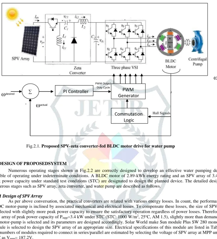
The structure of proposed SPV array-fed BLDC motor driven water pumping system employing a zeta converter is shown in Fig.2.1. The proposed system consists of (left to right) an SPV array, a zeta converter, a VSI, a BLDC motor, PI controller and a water pump. The BLDC motor has an inbuilt encoder. The pulse generator is used to operate the zeta converter. 2.2OPERATIONOFPROPOSEDSYSTEM
The SPV array generates the electrical power demanded by the motor-pump. This electrical power is fed to the motor pump via a zeta converter and a VSI. The SPV array appears as a power source for the zeta converter as shown in Fig.2.1. Ideally, the same amount of power is transferred at the output of zeta converter which appears as an input source for the VSI. In practice, due to the various losses associated with a dc– dc converter slightly less amount of power is transferred to feed the VSI. The pulse generator generates, through INCMPPT algorithm, switching pulses for insulated gate bipolar transistor (IGBT) switch of the zeta converter. The INC-MPPT algorithm uses voltage and current as feedback from SPV array and generates an optimum value of duty cycle. Further, it generates actual switching pulse by comparing the duty cycle with a high-frequency carrier wave. In this way, the maximum power extraction and hence the efficiency optimization of the SPV array is accomplished.
The VSI, changing dc output from a zeta device into ac, feeds the BLDC motor to drive a pump coupled to its shaft. Commutation ensures the right rotor rotation of the BLDC motor, whereas the motor speed only depends on the amplitude of the applied voltage. The amplitude of the applied voltage is adjusted exploitation the PWM technique. The specified speed is controlled by a speed controller, that is enforced as a standard proportional-integral (PI) controller. The distinction between the particular and needed speeds is input to the PI controller that then, supported this distinction, controls the duty cycle of the PWM pulses that correspond to the voltage amplitude required to maintain the desired speed for varying loads.
JETIR1810732 Journal of Emerging Technologies and Innovative Research (JETIR) www.jetir.org 243
ω
errorFig.2.1. Proposed SPV-zeta converter-fed BLDC motor drive for water pump
2.3DESIGNOFPROPOSEDSYSTEM
Numerous operating stages shown in Fig.2.2 are correctly designed to develop an effective water pumping devices, capable of operating under indeterminate conditions. A BLDC motor of 2.89-kWh energy rating and an SPV array of 3.4-kWh peak power capacity under standard test conditions (STC) are designated to design the planned device. The detailed designs of numerous stages such as SPV array, zeta converter, and water pump are described as follows.
2.3.1 Design of SPV Array
As per above conversation, the practical converters are related with various energy losses. In count, the performance of BLDC motor-pump is inclined by associated mechanical and electrical losses. To compensate these losses, the size of SPV array is selected with slightly more peak power capacity to ensure the satisfactory operation regardless of power losses. Therefore, the SPV array of peak power capacity of Pmpp=3.4 kW under STC (STC: 1000 W/m2, 25oC, AM 1.5), slightly more than demanded by
the motor-pump is selected and its parameters are designed accordingly. Solar World make Sun module Plus SW 280 mono SPV module is selected to design the SPV array of an appropriate size. Electrical specifications of this module are listed in Table 3.1 and numbers of modules required to connect in series/parallel are estimated by selecting the voltage of SPV array at MPP under STC as Vmpp= 187.2V.
TABLE 2.1 Specifications of Sun module plus SW 280 mono SPV Module
Peak Power, Pm (W)
280
Open circuit Voltage, Vo (V)
39.5
Voltage at MPP, Vm (V)
31.2
Short circuit current, Is (A)
9.71
Current at MPP, Im (A)
9.07
Number of cells connected in series, Nss
60
PWM Output Duty Cycle
ω
desired -ω
actual Hall SignalsPWM
Generator
Commutation
Logic
∑PI Controller
JETIR1810732 Journal of Emerging Technologies and Innovative Research (JETIR) www.jetir.org 244
The current of SPV array at MPP Impp is estimated as
Impp = Pmpp/Vmpp = 3400/187.2 = 18.16 A
(2.1) The no. of modules required to link in series is given as:
Ns= Vmpp/ V m = 187.2/31.2 = 6 (2.2) The no. of modules required to link in parallel is given as:
Np= Impp/ Im = 18.16/9.07 (2.3) 2.4 CONTROL OF PROPOSED SYSTEM
The planned device is controlled in two stages. These two control methods, viz., MPPT and electronic commutation, are explained as follows.
2.4.1 INC-MPPT Algorithm
An efficient and usually used INC-MPPT method in many SPV array based uses is utilized in order to minimize the power available from a SPV array and to facilitate a smooth starting of BLDC motor. This technique allows perturbation in either the SPV array voltage or the duty cycle. The formers call for a proportional-integral (PI) controller to generate a duty cycle for the zeta converter, which increases the complexity. Hence, the direct duty cycle control is adapted in this work. The INC-MPPT algorithm determines the direction of perturbation based on the slope of PPV−VPV curve, shown in Fig.3.3. As shown in Fig.3.3, the slope is zero at MPP, positive on the left, and negative on the right of MPP, i.e.,
dP
pv/dv
pv= 0; at mpp
dP
pv/dv
pv> 0; left of mpp
dP
pv/dv
pv< 0; right of mpp
dP
pv/dv
pv= D(v
pv* i
pv)/dV
pv= i
pv+ v
pv* d i
pv/d v
pv ≈i
pv+ v
pv∆i
pv/∆v
pv∆i
pv/∆v
pv = -i
pv/v
pv; at mpp
∆i
pv/∆v
pv > -i
pv/v
pv;left of mpp
∆i
pv/∆v
pv < -i
pv/v
pv; right of mpp
Thus, based on the relation between INC and instantaneous conductance, the controller decides the direction of perturbation as shown in Fig.2.2, and increases/decreases the duty cycle accordingly. For instance, on the right of MPP, the duty cycle is increased with a fixed perturbation size until the direction reverses. Ideally, the perturbation stops once the operating point reaches the MPP. However, in practice, operating point oscillates around the MPP. As the perturbation size reduces, the controller takes more time to track the MPP of SPV array. A knowledgeable contract among the tracking time and the perturbation extent is held to fulfill the objectives of MPPT and smooth starting of BLDC motor. In order to achieve smooth starting, the preliminary value of duty cycle is set as zero. In addition, an optimum value of perturbation size (ΔD=0.001) is selected, which contributes to soft starting and also minimizes oscillations around the MPP.
2.4.2 Electronic Commutation of BLDC Motor
The BLDC motor is controlled using a VSI operated through an electronic commutation of BLDC motor. An electronic commutation of BLDC motor stands for commutating the currents flowing through its windings in a predefined sequence using decoder logic. It symmetrically places the dc input current at the center of each phase voltage for 120o. Six switching pulses are
generated as per the various possible combinations of three Hall-effect signals. These three Hall-effect signals are produced by an inbuilt encoder according to the rotor position.
A particular combination of Hall-effect signals is produced for each specific range of rotor position at an interval of 60o. The
generation of six switching states with the estimation of rotor position is tabularized in Table II. It is perceptible that only two switches conduct at a time, resulting in 120o conduction mode of operation of VSI and hence the reduced conduction losses.
JETIR1810732 Journal of Emerging Technologies and Innovative Research (JETIR) www.jetir.org 245
high-frequency PWM switching are eliminated. A motor power company makes BLDC motor with inbuilt encoder is selected for proposed system.
III.MATLAB & SIMULATION RESULT
MATLAB could be a superior language for technical learning. It integrates computation, visual image, and programming in an easy-to-use setting wherever issues and solutions are expressed in acquainted notation. Typical uses include-
Math and computation Algorithm enlargement Data acquisition
Modeling, simulation, and prototyping Data analysis, exploration, and visual image Scientific and engineering graphics
MATLAB is an interactive system whose basic information part is an array that doesn't need orientating. this permits determination several technical computing issues, particularly those with matrix and vector formulations, during a fraction of the time it might want write a program during a scalar non-interactive language like C or algebraic language.
The MATLAB system consists of six main parts:
(a) Development atmosphere
This is the set of tools and facilities that facilitate to use MATLAB functions and files. several of those tools are graphical user interfaces. It includes the MATLAB desktop and Command Window, a command history, associate degree editor and program, and browsers for viewing facilitate, the space, files, and also the search path.
(b) The MATLAB mathematical relation Library
This is a huge assortment of process algorithms starting from elementary functions, like sum, sine, cosine, and complicated arithmetic, to a lot of refined functions like matrix inverse, matrix Eigen values, mathematician functions, and quick Fourier transforms.
(c)The MATLAB Language
This is a high-level matrix/array language with management flow statements, functions, knowledge structures, input/output, and object-oriented programming options. It permits each "programming within the small" to quickly produce fast and dirty throw-away programs, and "programming within the massive" to make large and sophisticated application programs.
(d) Graphics
MATLAB has in depth facilities for displaying vectors and matrices as graphs, yet as expansion and printing these graphs. It includes high-level functions for two-dimensional and three-dimensional knowledge visual image, image process, animation, and presentation graphics. It conjointly includes low-level functions that permit to completely customise the looks of graphics yet on build complete graphical user interfaces on MATLAB applications.
(e)The MATLAB computer programme Interface (API)
This is a library that permits writing in C and FORTRAN programs that move with MATLAB. It includes facilities for career routines from MATLAB (dynamic linking), career MATLAB as a process engine, and for reading and writing MAT-files.
(f) MATLAB Documentation
MATLAB provides extensive documentation, in both printed and online format, to help to learn about and use all of its features. It covers all the primary MATLAB features at a high level, including many examples. The MATLAB online help provides task-oriented and reference information about MATLAB features. MATLAB documentation is also available in printed form and in PDF format.
IV. RESULTS AND DISCUSSION
The simulation of a PV based Brushless DC Motor was finished. In order to remove the extreme possible power from the PV module, a PI based MPPT method along with a Zeta converter was modeled and analyzed. The modeling and performance analysis of BLDC motor under different operating speed conditions has been presented. It helps in simulation of various operating conditions of BLDC drive system. The performance analysis of BLDC motor under different operating speed conditions are presented it shows that, such a modeling is very useful in studying the drive system before taking up the devoted controller plan, accounting the relevant dynamic limitations of the motor.
A dc motor find wide application in industries and the speed can be controlled over a wide range, using either a variable supply voltage or by changing the strength of current in its field winding. The dc motors are used in propulsion electric vehicles, elevators, robot and hoists. To achieve the desired level of performance the motor requires suitable speed. The speed control is achieved by Zeta converters. Although conventional controllers are widely used in the industry due to their simple control structure and ease of implementation, these controllers pose difficulties. This project presents the optimized technique of particle
JETIR1810732 Journal of Emerging Technologies and Innovative Research (JETIR) www.jetir.org 246
swarm optimization and used to tune PI gain of the controller. For the purpose of comparison with conventional PI controller are considered from the simulation result, PSO technique offers an improvement in the quality of the speed response and better performance.
References
[1]
MenkaDubey, Shailendra Sharma, “Solar PV Stand-Alone Water Pumping System Employing PMSM Drive” Member IEEE and Rakesh Saxena Electrical Engineering Department 2014 IEEE Students’ Conference on Electrical, Electronics and Computer Science[2]
Hamza Bouzeriaetal “Speed Control of Photovoltaic Pumping System” international journal of renewable energy research, vol.4, no.3, 2014[3]
R. Teodorescu, M. Liserre and P. Rodriguez, Grid Converters for Photovoltaic and Wind Power Systems, 1st edition,John Wiley, United Kingdom, 2011.
[4]
M.G Villalva, J.R. Gazoli and E.R. Filho, “ComprehensiveApproach to Modeling and Simulation of Photovoltaic Arrays, ”IEEE Trans. Power Electronics, vol. 24, no. 5, pp. 11981208,Mar. 2009.[5]
W. J. A. Teulings, J. C. Marpinard, A. Capel, and D.O’Sullivan, “A new maximum power point tracking system,” Proc. IEEE 24th Annu. Power Electron. Spec. Conf., Jun. 1993, pp. 833–838.[6]
T. Esram and P. L. Chapman, “Comparison of photovoltaic array maximum power point tracking techniques,” IEEE Trans. Energy Conversion, vol. 22, no. 2, pp. 439-449, June 2007.[7]
F. Mayssa , F. Aymen and S. Lassaad, “ Influence of photovoltaic DC bus voltage on the high speed PMSM drive,” Proc. IEEE IECON Conf., Oct. 2012 , pp. 4489 - 4494.[8]
H. Moussa, M. Fadel and H. Kanaan, “A single stage DC-AC boost topology and control for solar PV systems supplying a PMSM,” inProc REDEC Conf., Nov.2012, pp.1-7.[9]
J. M. Shen, H. L. Jou and J. C. Wu, “Novel transformer less grid connected power converter with negative grounding for photovoltaic generation system,” IEEE Trans. Power Electronics, vol. 27, no. 4, pp. 1818-1829, Apr. 2012.[10]
A. K. Verma, B. Singh and T. Shahani, “Grid interfaced solar photovoltaic power generating system with power quality improvement at ac mains,” Proc IEEE ICSET Conf., Sep. 2012, pp. 177-182.[11]
H. Moussa, M. Fadel and H. Kanaan, “A single-stage DCAC boost topology and control for solar PV systems supplying a PMSM,” in Proc REDEC Conf., Nov. 2012, pp. 1-7.[12]
W. Lawrance, B. Wichert and D. Langridge, “Simulation and performance of a photovoltaic pumping system,” Proc. Power Electronics and Drive systems Conf., vol. 1, Feb. 1995.pp. 513–518.[13]
S. Henneberger, S. V. Haute, K. Hameyer and R. Belmans, “Submersible installed permanent magnet synchronous motor for a photovoltaic pump system,” Proc. IEEE Electric Machines and Drives Conf., May 1997, pp. WB2/10.1 - WB2/10.3. K.H. Ahmed, M.S. Hamad, S.J. Finney and B.W. Williams, “DC-Side Shunt Active Power Filter for Line Commutated Rectifiers to Mitigate the Output Voltage Harmonics,” IEEE Energy Conversion Congress and Exposition (ECCE), pp. 151-157, 12-16 Sept. 2010.P. Vas, Sensor less Vector and Direct Torque Control, Oxford University Press, 1998.
[14]
B. K. Bose, Power Electronics and Variable Frequency Drives Technology and Application, IEEE Press, New York, 1996.[15]
Ali Reza Reisi, Mohammad Hassan Moradi and ShahriarJamasb, “Classification and Comparison of Maximum Power Point Tracking Techniques for Photovoltaic System: A review,” Renewable and Sustainable Energy Reviews, Vol. 19, pp. 433-443, March 2013.[16]
W.V. Jones, “Motor Selection Made Easy: Choosing the Right Motor for Centrifugal Pump Applications,” IEEE Industry Applications Magazine, Vol. 19, No. 6, pp. 36-45, Nov.-Dec. 2013.[17]
Zhou Xuesong, Song Daichun, Ma Youjie and Cheng Deshu, “The Simulation and Design for MPPT of PV System Based on Incremental Conductance Method,” WASE International Conference on Information Engineering (ICIE), Vol. 2, pp. 314-317, 14-15 Aug. 2010.[18]
A. Shahin, A. Payman, J.-P. Martin, S. Pierfederici and F. Meibody-Tabar, “Approximate Novel Loss Formulae Estimation for Optimization of Power Controller of DC/DC Converter,” 36th Annual Conference on IEEE Industrial Electronics Society, pp. 373-378, 7-10 Nov. 2010[19]
B. Singh and V. Bist, “A Single Sensor Based PFC Zeta Converter Fed BLDC Motor Drive for Fan Applications,” Fifth IEEE Power India Conference, pp. 1-6, 19-22 Dec. 2012.[20]
M. Uno and A. Kukita, “Single-Switch Voltage Equalizer Using Multi-Stacked Buck-Boost Converters for Partially- Shaded Photovoltaic Modules,” IEEE Transactions on Power Electronics, No. 99, 2014.[21]
S. Satapathy, K.M. Dash and B.C. Babu, “Variable Step Size MPPT Algorithm for Photo Voltaic Array Using Zeta Converter - A Comparative Analysis,” Students Conference on Engineering and Systems (SCES), pp. 1-6, 12-14 April 2013.[22]
G.K. Dubey, Fundamentals of Electrical Drives, 2nd ed. New Delhi, India: Narosa Publishing House Pvt. Ltd., 2009.[23]
TETRA 142TR12, Brushless Servomotors [Online]. Available: http://www.eltrex-