149
Building Layout
6
Learning Objectives
After studying this chapter, you will be able to: • Explain the operation of the builder’s level
and level-transit.
• Explain the basic operation of a laser level system.
• Demonstrate proper setup, sighting, and leveling procedures.
• Measure and lay out angles using leveling equipment.
• Read the vernier scale. • Use a plumb line.
Technical Vocabulary
Before construction of a foundation or slab for a building can begin, the carpenter must know where the structure will be located on the property. This requires a series of steps involving the use of measuring tapes and building layout instruments. The place where a building is to be constructed is called a building site. Often, these sites are in communities where there are streets and where small tracts of land are broken up into smaller parcels called lots.
If the building site is a city lot, placing the building requires more steps. Most communities have strict requirements—buildings must be set back a certain distance from the street and main-tain minimum clearances from adjoining prop-erties. The local code must be carefully checked for these requirements before layout begins.
6.1 Plot Plan
Most, if not all, communities require the builder or owner to furnish a plot plan before Benchmark Builder’s level Building lines Building site Carpenter’s level Cut Datum Dumpy level Elevation Fill Grade Grade leveling Laser level Leveling rod Line of sight Lots Measuring tape Optical level Plumb Property line Station mark Steel tape Transit Vernier scale
Building site: The place where a building is to be constructed.
Lots: Small tracts of land broken up into smaller parcels.
150 Section 1 Preparing to Build
they will issue a building permit, Figure 6-1. A surveyor provides a survey of the site and locates stakes to indicate the boundaries, also called property lines. If there is a plot plan, it
indi-cates the location of the structure and distances to property lines on all sides. Surveyors should always locate the property lines. They should also draw the plot plan, if one is required.
Property lines: The boundaries of a site.
Figure 6-1. Providing a plot plan is the responsibility of the architect or owner. The plan shows the property boundaries, along with the building lines for the proposed building. Many communities require a plot plan before issuing a building permit.
The work of an engineer or surveyor protects the owner and builder from costly errors in measurement.
6.2 Measuring Tapes
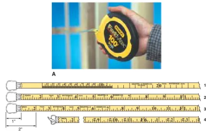
For measurements and layouts involving long distances, steel tapes, usually called measuring tapes, may be used, Figure 6-2. Tapes are available in lengths of 50′ to 300′. There are various types with differing graduations. A
carpenter will usually select one that is marked in feet, inches, and eighths of an inch. Surveyors, on the other hand, require a tape graduated in feet and decimal parts of a foot.
6.3 Establishing
Building Lines
Laying out a building means locating the outside corners of its foundation, then marking
Steel tape: Tape that comes in lengths of 50′ to 300′. It is used for measurements and layouts involving long distances. Also called measuring tape.
Measuring tape: Tape that comes in lengths of 50′ to 300′. It is used for measurements and layouts involving long distances. Also called steel tape.
Figure 6-2. Measuring tape. A—Long tapes for layout use are made in lengths of up to 300′. B—Measuring tapes are made with different systems and graduations. 1. Metric. 2. Feet and decimal graduations. 3. Feet, inch, and eighth-inch graduations. 4. Feet and eighth-inches with feet repeated at each eighth-inch mark. (The Stanley Co.; Keuffel & Esser)
A 1 2 3 4 1" 2" B
Building lines: The lines marking where the walls of a structure will be located.
them with stakes. Building lines are the lines marking where the walls of the structure will be. These lines must conform to code requirements on distance of the structure from boundary lines of the property.
Once the property lines are known and marked by the surveyor, the building lines can be found by measuring distances with a tape. See Figure 6-3. Be sure to observe proper setbacks and clearances. Carefully check the local code to ensure compliance. To start:
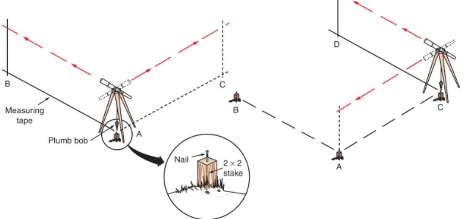
1. Locate the surveyor’s stakes marking the lot corners. Often, these are 2 × 2 wood stakes driven fl ush with the surface of the ground. A small nail driven in the top of the stake marks the exact corner of the property. 2. Measure the setback to locate the front
building line. Use a tape to measure the distance. To be accurate, the tape measure-ment must be perpendicular to the building line. String a line from stake-to-stake as needed.
3. Locate and mark the setbacks on the other three sides of the lot. Building lines must always be within these boundaries.
Using measuring tapes to
establish building lines
In the absence of optical instruments (which are described later), it is possible to lay out building lines for small structures with measuring tapes. To start: 1. Drive a 2 × 2 stake marking one corner of the
building. The exact location should never be closer to the lot lines than the intersection of two setback lines. Drive a nail in the top of the stake to mark the building line.
2. With a tape, measure off one side of the building dimension along the setback. 3. Drive another corner stake at this point and
drive a nail in the top to mark the dimension. This establishes the beginning point of the second side of the building.
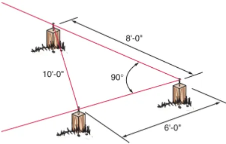
4. From the second stake, take a measurement for the intersecting building line. Use the 6–8–10 method shown in Figure 6-4 to establish a square corner.
5. In the 6–8–10 method, measure and mark 6′
along one building line already established. Next, measure 8′ on the intersecting building line and mark that location. Then, measure the diagonal distance from one mark to the other. Adjust the building line as needed until the diagonal line measures 10′ long. At that point, the corner formed by the intersecting lines is square. 6. Establish the remaining two building lines by
measuring the length and squaring the corners. 7. Test the accuracy of the layout by diagonally
measuring from corner to corner. If these measurements are equal, the building lines are laid out square.
6.4 Laying Out with
Leveling Instruments
In residential construction, it is important that building lines be accurately established in relation to lot lines. It is also important that footings and foundation walls be level, square, and the correct size. Street 10' 10' 10' 20'
Figure 6-3. A simple rectangular structure can be laid out by taking measurements, using lot lines as refer-ence points.
If the building is small, such as a 24′ garage, acarpenter’s level, line level, framing square, and rule are accurate enough for laying out and checking the building lines. But, as size increases, special leveling instruments are needed for greater accuracy and effi ciency.
6.4.1 Leveling Instruments
The builder’s level and transit are more accurate instruments for building layout. These leveling instruments are frequently used in construction work. They are basically telescopes with accurate spirit levels and must be mounted and leveled on a base that can be rotated. When the job is too large for the chalk line,straight-edge, level, and square, then leveling instru-ments should be used.
The optical device of these instruments oper-ates on the basic principle that a line of sight is a straight line that does not dip, sag, or curve. Any point along a level line of sight will be at the same height as any other point. Through the use of these instruments, the line of sight replaces the chalk line, line level, and straightedge.
The builder’s level, also called a dumpy level or optical level, is shown in Figure 6-5. It consists of an accurate spirit level and a tele-scope assembly attached to a circular base that swivels 360°. Leveling screws are used to adjust the base after the instrument has been mounted on a tripod. The telescope is fi xed so that it does not move up or down, but it rotates on the base. This permits any angle in a horizontal plane to be laid out or measured.
The transit is like the builder’s level in most respects, Figure 6-6. However, the telescope can be pivoted up and down 45° in each direc-tion. Using this instrument, it is possible to accurately measure vertical angles. The transit is also used to determine if a wall is perfectly plumb (vertical) by sighting the vertical cross-hair while pivoting the scope up and down. Its vertical movement also simplifi es the operation of aligning a row of stakes, especially when they vary in height.
In use, both the builder’s level and transit are mounted on tripods, Figure 6-7. Some models,
Carpenter’s level: Tool used for laying out and checking the building lines.
Builder’s level: An optical device used by builders to determine grade levels and angles for laying out build-ings on a site. Also called a dumpy level or an optical level.
Transit: Optical leveling instrument commonly used for building layout.
Line of sight: A straight line that does not dip, sag, or curve. Any point along a level line of sight is at the same height as any other point.
Plumb: Exactly perpendicular or vertical; at a right angle to the horizon or fl oor.
90° 8'-0"
6'-0" 10'-0"
Figure 6-4. To check whether a corner is square, mark 6′ along one building line and 8′ on the intersecting building line. If the distance between the marks is 10′, the corner is square.
Instrument level vial Eyepiece Horizontal tangent screw Horizontal clamp screw Leveling screws Horizontal graduated circle Lens
Figure 6-5. The builder’s level is used to sight level lines and lay out or measure horizontal lines. (David White)
like the one shown, have legs whose length can be independently adjusted. This feature makes the tripod easier to level on sloping ground. It also permits the legs to be shortened for easier handling and storing.
When sighting over long distances, use a leveling rod. See Figure 6-8. It is a long rod marked off with numbered graduations. It allows differences in elevation between the position of the level and various positions where the rod is held to be easily read. The rod is especially useful for surveying. The person operating the level can make the readings or the target can be adjusted up and down to the line of sight and then the person holding the rod (rod holder) can make the reading.
Tripod head
Leg
Ground spike Tie strap
Leg clamp
Figure 6-7. Tripod legs hinge at top and are adjustable for use on uneven terrain. (David White)
Eyepiece Horizontal clamp screw Vertical tangent screw Vertical clamp screw Vertical arc Focusing knob Index vernier Horizontal graduated circle Telescope lens
Figure 6-6. A transit can be used to lay out or check both level and plumb lines. It can also be used to measure angles in either the horizontal or vertical planes. (David White)
Leveling rod: A long rod marked off with numbered graduations that is used, along with a builder’s level or transit, to sight differences in elevation over long distances.
A B
Figure 6-8. Leveling rod with target. The target can be moved up or down to match the line of sight of the transit. (David White)
The rod shown in Figure 6-8 has graduations in feet and decimal parts of a foot. This is the type used for regular surveying work. Rods are also available with graduations in feet and inches.
When sighting short distances (100′ or less), a regular wooden or metal folding rule can be held against a wood stake and read through the instrument. This procedure will be satisfac-tory for jobs such as setting grade stakes for a footing. Always be sure to hold the stake and rule in a vertical position.
Working Knowledge
Leveling instruments and equipment will vary somewhat, depending on the manu-facturer. Always carefully read and study the instructions for a given brand.
6.4.2 Care of Leveling
Instruments
Leveling instruments are more delicate than most other carpentry tools and equip-ment. Special precautions must be followed in their use so they will continue to provide accu-rate readings over a long period of time. Some suggestions follow:
• Keep the instrument clean and dry. Store it in its carrying case when not in use. • When the instrument is set up, have a plastic
bag or cover handy to use in case of rain. If the instrument becomes wet, dry it before storing.
• When moving the instrument from its case to the tripod, grip it by the base.
• Never leave the instrument unattended when it is set up near moving equipment. • When moving a tripod-mounted instrument,
handle it with care. Hold the instrument upright; never carry it in a horizontal position.
• Never over-tighten leveling screws or any of the other adjusting screws or clamps.
• Always set the tripod on fi rm ground with the legs spread well apart. When it is set up on a fl oor or pavement, take extra precautions to ensure that the legs will not slip. • For precision work, permit the instrument
to reach ambient (air) temperature before making readings.
• When the lenses collect dust and dirt, clean them with a camel hair brush or special lens paper.
• Never use force on any of the adjustments. They should easily turn by hand.
• Have the instrument cleaned, lubricated, and checked yearly by a qualifi ed repair station or by the manufacturer.
Setting up the instrument
Use the following procedure to set up a tripod-mounted instrument.
1. Place the tripod so it will be a fi rm and stable base for the instrument. The base of the legs should be about 3′-6″ apart. Make sure the points are well into the ground and the head is fairly level.
2. Check the wing nuts on the adjustable legs. They should be tight enough to carry the weight of the instrument without collapsing or sinking. Tighten the hex nuts holding the legs to the head to the desired tension.
3. Carefully lift the instrument from its case by the base plate. Before mounting the instrument, loosen the clamp screws. On some instruments, the leveling screws must be turned up so the tripod cup assembly can be hand-tightened to the instrument mounting stud. Set the telescope lock lever of the transit in the closed position. 4. Attach the instrument to the tripod. If it is to
be located over an exact point, such as a benchmark, attach the plumb bob and move the instrument over the spot. Do this before the fi nal leveling.
Leveling the instrument
Leveling the instrument is the most important operation in preparing it for use. None of the read-ings taken or levels sighted will be accurate unless the instrument is level throughout the work. To level the instrument:
1. Release the horizontal clamp screw and line up the telescope so it is directly over a pair of the leveling screws.
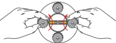
2. Grasp the two screws between the thumb and forefi nger, as shown in Figure 6-9. Uniformly turn both screws with your thumbs moving toward each other or away from each other. 3. Keep turning until the bubble of the level vial
is centered between the graduations. You will fi nd on most instruments that the bubble travels in the direction your left thumb moves. SeeFigure 6-10. Leveling screws should bear fi rmly on the base plate. Never tighten the screws so much that they bind.
4. When the bubble is centered, rotate the tele-scope 90° (so it is over the other pair of leveling screws) and repeat the leveling operation. 5. Recheck the instrument over each pair of screws.
When the instrument is level at both positions, the telescope can be turned in a complete circle without any change in the bubble.
Sighting
Most builder’s levels have a telescope with a power of about 20×. This means that the object being sighted appears to be 20 times closer than it actually is. The procedure for sighting is easy to learn:
1. Line up the telescope by sighting along the barrel and then look into the eyepiece, Figure 6-11.
2. Adjust the focusing knob until the image is clear and sharp.
3. When the crosshairs are in approximate posi-tion on the object, Figure 6-12, tighten the horizontal-motion clamp.
4. Make the fi nal alignment by turning the tangent screw.
Figure 6-9. Adjust leveling screws to center the bubble in the level vial.
Bubble
Figure 6-10. The bubble of the level vial will gener-ally move in the same direction as the left thumb. This bubble needs to move left.
Figure 6-11. Sighting a level line with a builder’s level. Both eyes are kept open during sighting. This reduces eyestrain and provides the best view. Hand signals tell the rod holder whether to raise or lower the target on the leveling rod. (Kasten-Weiler Construction)
6.5 Using the
Instruments
A carpenter can use leveling instruments to prepare the building site for excavation and grade leveling. Jobs that can be done with leveling instruments include:
• Locating the building lines and laying out horizontal angles (square corners). • Finding grade levels and elevations. • Determining plumb (vertical) lines.
For layout, the builder’s level or transit must start from a reference point. This can be a stone marker in the ground, point on a manhole cover, or mark on a permanent structure nearby. The point where the instrument is located is called the station mark. It may be the benchmark, the corner of the property, or a previously marked point that is to be a corner of the building. This
might be a stake with a nail in it or the intersec-tion of two string lines marking the corner of a building line.
6.5.1 The Horizontal
Graduated Circle
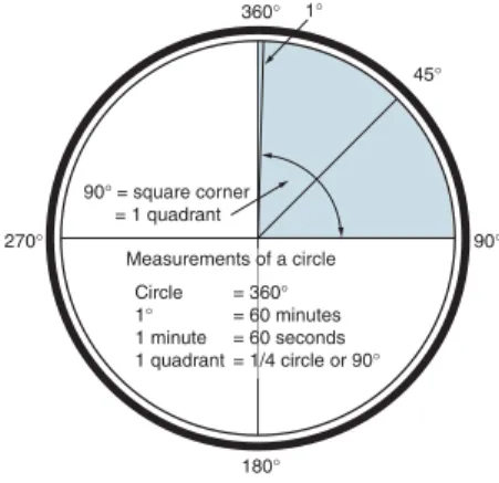
Laying out corners with the transit requires an understanding of how the horizontal gradu-ated circle is marked. It is divided into spaces of 1°,Figure 6-13. When you swing (rotate) the tele-scope of the builder’s level or transit, the gradu-ated circle remains stationary, but another scale, called the vernier scale, moves. It is marked off in 15-minute intervals. When laying out or measuring angles where there are fractions of degrees involved, you will use this vernier scale.
Figure 6-14A shows a section of the gradu-ated circle and the scale. It reads 75°. Notice that the zero mark on the vernier exactly lines up with the 75° mark. Now look at Figure 6-14B. The zero mark has moved past the mark for 75°, but is not on 76°. You need to read along the vernier scale until you fi nd a mark that is closest to being directly over a degree mark on
Station mark: The reference point where a builder’s level or transit is set up when laying out building lines or fi nding grade levels and elevations. It must be a type of marker that will not be disturbed by any construc-tion activity.
Benchmark: A mark on a permanent object fi xed to the ground from which grade levels and elevations are taken for construction of a building. Sometimes offi -cially established by government survey.
Vernier scale: Device on a transit that measures minute portions of an angle.
270° 90° 180° 360° 45° 1° Measurements of a circle Circle 1° 1 minute 1 quadrant = 360° = 60 minutes = 60 seconds = 1/4 circle or 90° 90° = square corner = 1 quadrant
Figure 6-13. The graduated circle of a transit corre-sponds to the 360° of a full circle; 90° represents a quadrant, which would give you a square corner for a building.
Crosshairs
3
A B
Figure 6-12. View through the telescope. A—Cross-hairs vertically and horizontally split the image area in half. B—The object in the view should be centered on the crosshairs.
the circle. That number is 45. The reading is 75°, plus the number on the vernier, 45 minutes.
Vernier scales will not be the same on all instruments. Study the operator’s manual for instructions about the particular model you are using.
6.5.2 Laying Out and
Staking a Building
Staking out is done before establishing the grade level. It begins with locating the lot lines. Corners of the lot should normally be marked with stakes. Then, proceed:
1. Center and level the instrument (builder’s level or transit) over the lot corner stake. Measure the setback called for by local codes. Sight across to the opposite corner stake. 2. Drive a 2 × 2 stake at the setback in line with
the lot stakes. Use the transit or builder’s level
to check alignment. The vertical and horizontal crosshairs should center on the top of the stake. Drive a nail in the top-center of the stake. 3. Place another stake at the correct setback for
one side of the property line. You are now ready to stake out the building lines.
Staking a building
Staking out building lines requires two persons. When a builder’s level is used, the second person will use a rod that must be plumbed along the line of sight. Since a transit can pivot up and down, the second person uses a stake to locate corners along the building line.
1. Attach a plumb bob to the center screw or hook on the underside of the instrument. Some instruments have an optical plumb for zeroing in over a point. Shift the tripod until the point of the plumb bob is directly over the point marking the corner of the building lines. This is at point A on line AB, as shown in Figure 6-15.
2. Level the instrument before proceeding further. Recheck for plumb.
3. From point A (or station A), turn the telescope so the vertical crosshair is directly in line with the edge of a stake or rod held at point B. When using a transit, sight the telescope on the stake. 4. Use a measuring tape along line AB to locate
distance to the corner. Drive a corner stake at this point.
5. Set the horizontal circle on the instrument at zero to align with the vernier zero and swing the instrument 90° (or any other required angle). 6. Position the rod or stake along line AC so it
aligns with the crosshairs.
7. Locate the other corner along line AC using a measuring tape.
8. Move the instrument to point C, sight back to point A and then turn 90° to locate the line of sight to point D.
9. Measure the distance to point D and place a stake.
10. Use a measuring tape to check the diagonal distances. If these are equal, the building line is square.
If the resulting fi gure is a rectangle or square, you have completed the layout. However, you may want to move the instrument to point D to check your work.
80 70 60 15 30 45 60 0 15 30 45 60 50 40 30 90 80 70 60 50 A B 75°, 45 Minutes 80 70 60 15 30 45 60 0 15 30 45 60 50 40 30 90 80 70 60 50 75° Vernier scale
Figure 6-14. Reading the horizontal circle of a transit. A—When the zero mark of the vernier is exactly on a degree mark, the reading is an even degree. In this case, the reading is 75°. B—When the zero mark is between degrees, read across the vernier to fi nd the minute mark that aligns with a degree mark. This reading is 75°, 45′. (David White)
In practice, you will fi nd that it is diffi cult to locate a stake in a single operation. This is espe-cially true when using a builder’s level, where the line of sight must be “dropped” to ground level with a plumbed rod or straightedge. Usually, it is best to set a temporary stake, as in Figure 6-16. Mark it with a line sighted from the instrument. Then, with the measuring tape pulled taut and aligned with the mark, drive the permanent stake and locate the exact point as shown.
All major rectangles and squares of a building line can be laid out using leveling instruments in the manner just described. After batter boards are set and lines attached, the carpenter’s level and square can be used to locate stakes for small projections and irregular shapes.
Distance measured with tape Alignment sighted from stake A Mark line of sight Temporary stake Stake at position C
Figure 6-16. A temporary stake may be used to estab-lish an exact point. First, set the temporary stake and mark the line of sight on it. Drive a second stake and transfer the mark from stake A.
Nail B B A A C C D 2× 2 stake Plumb bob Measuring tape
Figure 6-15. Steps for laying out building lines. Left—Locate the instrument over a stake marking a corner. Line up 0 on the instrument circle with the building line AB. Swing the instrument 90° to establish line AC. Right—Move the instrument to point C to establish point D. Rod must be used when the instrument is a builder’s level. Rod must be held plumb using a plumb line or carpenter’s level. A transit is a much better instrument in this operation since it is not necessary to use the rod. Simply swivel the transit telescope and sight on the corner stake.
6.5.3 Finding Grade Level
Many points on the building site need to be set at certain elevations or grade levels. These points might include:• The depth of excavation, such as for a basement.
• The fi nished height (elevation) of the foundation footings.
• The height (elevation) of foundation walls. • The elevation of fl oors.
• Site features, such as proper grading to ensure that surface water is directed away from the building.
• Bearing elevation (point at which footings contact the earth) for footings in order to ensure adequate frost protection of the foundation.
• Establishing rise and run of steps and walkways as part of the exterior of the structure.
Not all building sites are level. Finding the difference in the grade level between several points or transferring the same level from one point to another is called grade leveling.This operation is immediately useful to the exca-vator, who must determine how much earth must be removed to excavate a basement or trench a foundation footing. Grade leveling is also useful to determine how much earth must be deposited in a particular area to achieve a desired height or elevation at that location.
When the leveling instrument has been set level, the line of sight will also be level. The read-ings can be used to calculate the difference in elevation, Figure 6-17. If the building site has a large slope, the instrument may need to be set up more than once between the points where you want to take readings. The fi rst reading is taken with the rod in one position. Then, the instru-ment is carefully rotated 180° to get the reading at a second rod position. This position may be higher or lower than the fi rst position. From a practical standpoint, it is simpler to work from a higher point on the site than a lower point. Depending on the actual slope, this measure-ment can often be made with a single reading.
The term grade means the level of the ground. Elevation refers to the major structural levels
of the building. More specifi cally, these levels include the top of the footing, top of the founda-tion wall, and fi nish height of the fi rst fl oor.
There should be a reference point (level) for all elevations established on the building site. It is called the benchmark, datum, or simply the beginning point. This point must remain
A B B A 5'-2" 5'-9"
Figure 6-17. Establishing a grade level and fi nding the difference between two points on a building lot. Top— Level the instrument and take a line of sight reading on point A. Mark down the rod reading. Bottom—Swing the telescope 180° and take a line of sight reading on the rod. Compare the two elevations. In this example, point A is 7″ higher than point B.
Grade leveling: Finding the difference in the grade between several points or transferring the same level from one point to another.
Grade: Quality of lumber. Also, the height or level of a building site.
Elevation: The height of an object above grade. Also, a type of drawing that shows the front, rear, and sides of a building.
Datum: An established reference point for deter-mining elevations in an area. Also called benchmark or simply the beginning point.
undisturbed during the construction of the building project. A stake driven at one corner of the lot or building site, or even a mark chis-eled into concrete curbing, often serves as the benchmark.
Checking grade
Building sites are rarely perfectly level. All have high and low points. These highs and lows need to be determined before the height of the foundation is established. This job is easier when the site is fairly level, as in Figure 6-17.
1. Locate the instrument midway into the site, then level the instrument.
2. Take a line-of-sight reading on a rod held at one edge of the site.
3. From the position of the target on the rod, note the elevation (5′-2″ in Figure 6-17) and record it. Surveyors keep a notebook for such recording, since many people may need to refer to the readings. Carpenters generally jot readings on a piece of scrap lumber. Usually, they are the only ones needing to refer to the readings.
4. Rotate the telescope 180°. Take a line-of-sight reading on the rod located at the opposite side of the site.
5. Note the elevation at the target position on the rod (5′-9″ in Figure 6-17). Record it as before. 6. Subtract the lower elevation from the higher
one to fi nd the difference (7″). This number is the actual vertical increase or decrease from one known point to another.
When setting grade stakes for a footing or erecting batter boards, set the instrument in a central location on the site, as shown in Figure 6-18. The distances to the target (or rod) will be roughly equal. This will improve the accuracy of the readings taken for each corner. An elevation established at one corner can be quickly transferred to other corners or points in between.
6.5.4 Setting Footing Stakes
Grade stakes for footings are usually fi rst set to the approximate level “by eye.” They are then carefully checked with the rod and level as they are driven deeper. The top of each stake should be driven to the required elevation.Sometimes, reference lines are marked on construction members, stakes, or other objects near the work. The carpenter then transfers them to the formwork with a carpenter’s level and rule as needed. This eliminates the need to repeatedly establish the same elevation.
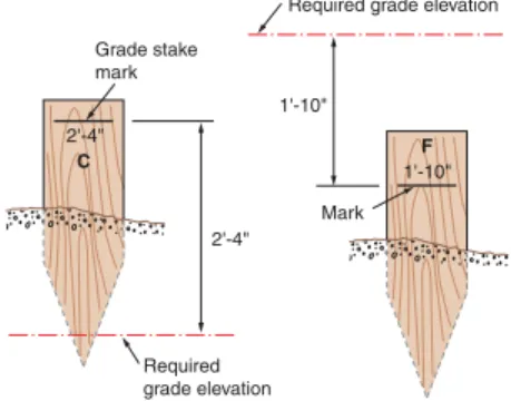
There may be situations where the existing grade will not permit the setting of a stake or reference mark at the actual level of the grade. In such cases, a mark is made on the stake with the information on how much fi ll to add or remove. The letters C and F, standing for cut and fi ll, are generally used. See Figure 6-19 for an example of how stakes are marked.
Pier footing
Building line
Tripod
Figure 6-18. A central location for the instrument will make fi nding and setting grade stakes easier and more accurate.
Cut: The process of removing material to achieve the desired grade.
Fill: The process of adding material to achieve the desired grade.
Using multiple readings
When laying out steeply sloped building plots or carrying a benchmark to the building site, it will likely
be necessary to set up the instrument in several locations. Figure 6-20 shows how reading from two positions is used to calculate, establish, or determine differences in grade at various locations on the plot. 1. Set up the instrument midway between two
points on the plot. In Figure 6-20, these are identifi ed as points A and B.
2. Take a line-of-sight reading at point A (or station A). Record the reading in the notebook. In this case, the reading is 5′-8″.
3. With the rod at point B and the instrument still at setup #1, take a second reading. Record the reading in the notebook. In this instance, the reading is 2′-6″.
4. Move the instrument to a point midway between points B and C. Level it as before.
5. Take a second reading on point B and record it. In this example, the reading is 6′-0″. 6. With the rod located at point C, take a reading
by rotating the telescope 180°. Note and record the elevation. In this case, the reading is 2′-4″. 7. Calculate the differences in grade level for
each pair of stakes, as shown in Figure 6-20.
8. Add the resulting distances and subtract the “minus” sum from the “plus” sum to fi nd the difference in grade from one edge of the plot to the other. The result, in this example, is 6′-10″.
Required grade elevation
Required grade elevation C 2'-4" 1'-10" Grade stake mark Mark 1'-10" 2'-4" F
Figure 6-19. Cut and fi ll stakes are used to tell the excavator how much material must be removed or added to reach grade level. The letter C means “cut” (remove) and the letter F means “fi ll” (add).
6'-0" 2'-6" 5'-8" Curbing used as benchmark A B (Minus reading) C 2'-4" Setup #1 Setup #2 Setup # 1 2 Sum Plus sight 5'-8" 6'-0" 11'-8" Minus sight 2'-6" 2'-4" 4'-10" Surveyor s Notebook 11'-8" – 4'-10" = 6'-2"
Figure 6-20. When there is a large slope on the property or when long distances are involved, the transit will need to be set up in two or more locations.
6.5.5 Running Straight
Lines with a Transit
Although the builder’s level can be used to line up stakes, fence posts, poles, and roadways, the transit is more accurate for these tasks, espe-cially when different elevations are involved. Set the instrument directly over the reference point. Level the instrument and then release the lock that holds the telescope in the level position. Swing the instrument to the required direc-tion or until a stake is aligned with the vertical crosshair. Tighten the horizontal circle clamp so the telescope can move only in a vertical plane. Now, by pointing the telescope up or down, any number of points can be located in a perfectly straight line. See Figure 6-21.
6.5.6 Vertical Planes and
Lines
Beyond the leveling tasks just mentioned, the transit is a good instrument for:
• Measuring vertical angles above or below the line of sight.
• Plumbing building walls, columns, and posts.
Measuring vertical angles
1. Position the instrument near the structure. Level the instrument.
2. Release the lever that holds the telescope in a horizontal position.
3. Swing the instrument vertically.
4. Set the horizontal crosshair at the point you wish to measure.
5. Tighten the vertical clamp.
6. Make a fi nal, fi ne adjustment with the tangent screw to locate the horizontal crosshair exactly on the point.
7. Read the vertical angle on the vertical arc scale and the vernier.
Establishing plumb lines
Plumb lines can be checked or established by first operating the instrument as shown in
Figure 6-22. As you tilt the telescope up and down, all of the sighted points are located in the same vertical plane. To plumb structures, such as posts or walls, follow these steps and refer to
Figure 6-23:
1. Set up the transit at a distance from the object equal to at least equal to the height of the object. Tilt the telescope to sight on the base. 2. Loosen the horizontal clamp and line up the
vertical crosshair with the base of the object. 3. Tighten the horizontal clamp.
4. Tilt the telescope upward to the top of the object. If the object is plumb, the crosshair will be on the same plane as it is at the base. 5. If object is not plumb, adjust the brace to bring
the object into plumb.
6. Move the transit to a second position, prefer-ably 90° either to the right or left, and repeat the procedure.
A plumb bob and line may often be the most practical way to check vertical planes and lines. For layouts inside a structure, where a regular builder’s level or transit is impractical, use a plumb line.
A B C
Figure 6-21. How to use the transit to align a row of stakes.
6.6 Laser Systems
The laser has been integrated into the building industry. Manufacturers have been able to produce low-power, visible lasers in small, inexpensive units. Using various names— laser plane, construction laser, laser transit, or
simply laser level—the operating principle of the various units is essentially the same. They perform most of the functions of a conventional transit. However, they need only one person to carry out any layout operation. Some are designed to rotate 360°, allowing the operator to establish level lines throughout the structure without moving the instrument.
Safety Note
For safety, power output of the laser is controlled. Federal regulations limit Class II construction lasers to 1 milliwatt and Class IIIa units to less than 5 milliwatts. These levels are safe for the eyes so long as the user does not stare into the beam. Manufacturer’s cautions should be carefully observed.
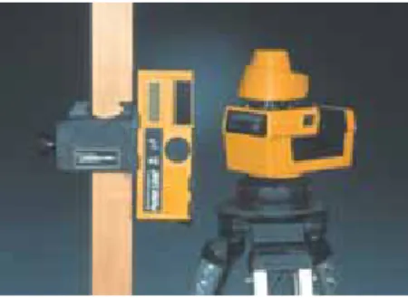
A laser level can be set to emit a laser beam for a full 360° without being tended by an instrument person. Figure 6-24 shows the laser transmitter and its receiver. During use, the transmitter is untended. The receiver can be tended by a rod
Figure 6-24. Laser level and receiver. The transmitter is at the right and the receiver is at the left. (Spectra-Physics Laserplane, Inc.)
Laser level: Leveling instrument that emits a level laser beam over 360°without being attended. A receiver attached to a rod and attended by a rod holder makes a sound when the laser beam strikes it.
C
B
A
Figure 6-22. A transit can be used to lay out or check points in a vertical plane.
90°
Figure 6-23. Using the transit to plumb an object. First, align the vertical crosshair with the base. Then, swing the telescope to or near the top. Adjust the object for plumb as needed. Reposition the instrument at a 90°
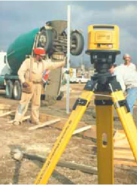
holder, Figure 6-25, or it can be attached to an excavator or backhoe, Figure 6-26. Operators of excavating equipment can work the entire job site without stopping to check grade levels. The laser level continuously monitors grade, elimi-nating excess excavation.
The operator places the bucket or blade cutting edge on the benchmark or fi nished elevation. Then, the receiver is adjusted up or down on the machine and the operator tightens the clamp when the “on-grade” point is reached. The receiver “catches” the laser beam from the rotating transmitter and signals the operator whether measured surface is above, below, or on grade.
The laser level is also adapted to other construction tasks to establish either level or plumb lines. Horizontal operations for which it might be used include leveling suspended ceiling grids and leveling raised-access computer fl oors. Vertical operations include plumbing partitions, curtain walls, posts, columns, elevator shafts, or any operation requiring a vertical reference point.
Figure 6-25. A rod holder moves the receiver up or down until it is on line of sight with the laser level. (Spectra-Physics Laserplane, Inc.)
Figure 6-26. A laser receiver can be attached to an excavating machine, speeding up the excavation process. (Spectra-Physics Laserplane, Inc.)
ON THE JJOB
Surveyor/Surveying Technician
Surveyors and surveying technicians establish offi cial land boundaries and the exact location and extent of building sites and other land uses. Survey parties, usually consisting of several surveying tech-nicians under the direction of a party chief, tradition-ally use a variety of instruments to establish property boundaries and elevations. A licensed surveyor uses this information, combined with research in legal records and other sources, to prepare an offi cial map called a plat of survey that establishes the offi cial loca-tion of the property. Such a survey is often required before a deed can be issued in a property transfer.
Surveyors are professionals who must meet educational and experience requirements and pass licensing examination. In the past, surveyors could be licensed by gaining experience on a survey party, then passing a licensing exam. However, most states today require a four-year degree in surveying or a related fi eld, such as civil engineering, in addition to the exam and fi eld experience.
Surveying technicians often have some postsecondary training, usually in a community college certifi -cate or associate degree program. High school courses
in algebra, geometry, trigonometry, and drafting are good preparation. Technicians are usually respon-sible for using optical, physical, and electronic tools to make the needed measurements in the fi eld. While traditional tools such as theodolites and measuring tapes are still used, more and more survey parties are working with electronic distance-measuring devices and global positioning system receivers that use satel-lite data for precise location-fi nding. Advancement to party chief is possible with additional formal training and experience.
Working conditions for survey parties can be extreme, since they are exposed to all kinds of weather conditions and may have to carry equipment for long distances in rugged terrain. Licensed surveyors often work in the fi eld, but also spend time indoors doing research, data analysis, and report writing.
Approximately 2/3 of all surveyors and surveying technicians are employed by architectural and engi-neering fi rms or companies providing related services. Most of the remaining employment is provided by government at all levels, ranging from federal agen-cies, such as the U.S. Forest Service, to state and local planning departments and highway agencies. A rela-tively small number of surveyors are self employed.
Summary
The correct location on the building site must be identifi ed before the foundation or slab can be constructed. Laying out a building involves locating the outside corners of the foundation, driving stakes, and then stretching building lines between stakes to mark where the walls will be. Measuring tapes can be used for layout work, but leveling instruments are more precise. Leveling instruments are also used to establish grades and elevations. Laser levels are replacing conventional transits and levels in building site layout. Their biggest advantage is requiring only one person to take measurements, rather than two.
Test Your Knowledge
Answer the following questions on a separate piece of paper. Do not write in this book.
1. For surveying work, a measuring tape with graduations reading in feet and ______ is required.
2. What are building lines?
3. Explain how to check whether corners of a building layout are square.
4. In the use of leveling instruments, the ______ replaces the chalk line and straightedge. 5. The builder’s level consists of a telescope
assembly that is mounted on a ______ base. 6. The most important operation in setting
up a builder’s level or transit is ______ the instrument.
7. When sighting through the telescope, you should adjust the ______ until the image is sharp and clear.
8. True or False? The vernier scale is used to
measure angles in fractions of a degree. 9. To position a leveling instrument without an
optical plumb directly over a given point, a ______ is used.
10. When setting grade stakes for a building footing, the instrument should be set up in a ______ location.
11. True or False? A laser level can check the level of an entire structure from one position.
Curricular Connections
Mathematics. Make a study of the proce-dures you would follow and calculations you would make to determine the height of a fl agpole, tall building, or mountain, using a transit and trigonometric functions. Use the information to determine the height of at least one tall object in your community. Prepare a report for your class explaining the theory and how you proceeded.
Outside Assignments
1. Study the catalog of a supplier or manufac-turer and develop a set of specifi cations for a builder’s level. Be sure it includes a good carrying case. Also select a suitable tripod and measuring tape. Secure prices for all of the items.
2. Through drawings and a written descrip-tion, tell how you would proceed to lay out a baseball diamond using a transit.