INTERNATIONAL CONFERENCE ON ENGINEERING DESIGN ICED 03 STOCKHOLM, AUGUST 19-21, 2003
NEW THEORY-BASED CONCEPTS FOR PDM AND PLM
Christian Weber, Till Deubel
Abstract
The objective of this paper is to discuss future developments and potentials for Product Data Management (PDM) and Product Lifecycle Management (PLM) systems, based on a new theory-based approach to modelling products and product development processes (“Property-Driven Development/Design”, PDD). A special focus is placed on the management and con-trol of the product development process.
Keywords: Design Theory, Property-Driven Development/Design (PDD), PDM, PLM, Design Process Management
1.
Introduction
Today’s PDM- and PLM-systems are confronted with the task to deal with data of all kinds of tools and entities involved in the product development process. They store and move data, but they usually do not know anything about the content and the interrelationships of the data they handle. PDM/PLM usually focuses on the handling of data according to predefined (pro-cess) patterns and procedures.
This paper introduces a concept for a new kind of PDM/PLM, based on a new approach to development/design theory called “Property-Driven Development/Design” (PDD). The sys-tem proposed tackles some of the shortcomings of today’s PDM/PLM-syssys-tems. The paper starts with a brief description of PDD, in the second part the concept and potential advantages of an extended PDM/PLM-system based on PDD are outlined.
2.
Property-Driven Development/Design (PDD)
The concept of PDD is mainly based on the distinction between characteristics (in German: “Merkmale”) and properties (“Eigenschaften”) of a product: The characteristics describe the structure and the shape of a product (“Struktur und Gestalt”, “Beschaffenheit”), the properties describe the product’s behaviour (“Verhalten”). While the characteristics can be directly de-termined by the designer, the properties depend on the chosen characteristics, but also on other factors, and can not be directly influenced by the designer.
The characteristics are very similar to what Hubka and Hubka/Eder call “internal properties” [Hubk-73, Hubk-84, HuEd-92, HuEd-96] and what Suh calls “design parameters” [Suh-90], i.e. parts’ structure, geometry, material and surface characteristics of a product. The properties are related to Hubka’s and Eder’s “external properties” and to Suh’s “functional require-ments”, e.g. weight, safety and reliability, aesthetic properties, but also things like “manufac-turability”, “assemblability”, “testability”, “environmental friendliness” and cost of a product.
To be able to handle characteristics and properties – literally thousands of them in complex products – and to keep track of them in the development process they have to be structured.
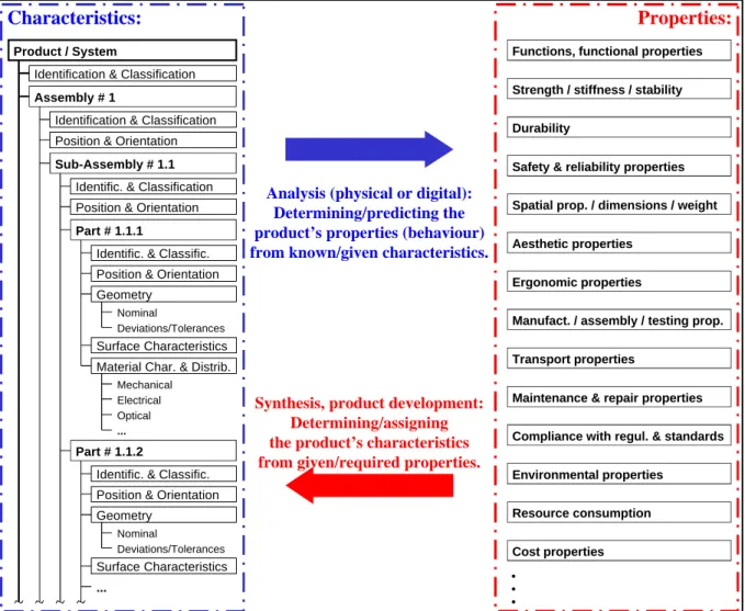
Figure 1 shows on the left a fairly obvious proposition for the (hierarchical) structuring of characteristics which follows the parts’ tree of a product. (Other methods of structuring char-acteristics are theoretically possible, but not discussed here.) On the right of figure 1 the most important (“top-level”) classes of properties are given as a first entry into their structuring. Of course, these also should be structured more deeply by further decomposing them. It is the authors’ hypothesis that the structuring as well as the “ranking” of properties are always spe-cific to individual industries (product classes), often even spespe-cific to individual companies within the respective branch of industry, and are even time-dependent. Because the issue of this article is on a different field the discussion on the further structuring of properties is not continued here.
Figure 1: Characteristics and properties with the two main relations between the two
Figure 1 also shows the two main relations between characteristics and properties which cor-respond with the two main activities in the product development/design process:
• Analysis: Based on known/given characteristics of a product its properties are deter-mined, or – if the product does not yet exist in reality – predicted. Analyses can, in prin-ciple, be performed by experiments (using a physical model/mock-up or a prototype) or “virtually” (e.g. using digital simulation tools).
• Synthesis: Based on given, i.e. required, properties the product’s characteristics are to be assigned. Synthesis is the main activity in product development: For the customer mainly
Characteristics: Properties:
Analysis (physical or digital): Determining/predicting the product’s properties (behaviour) from known/given characteristics.
Synthesis, product development: Determining/assigning the product’s characteristics from given/required properties. Assembly # 1
Sub-Assembly # 1.1
Part # 1.1.1
Part # 1.1.2
Identific. & Classific.
Nominal
Deviations/Tolerances
Surface Characteristics Material Char. & Distrib.
Mechanical Electrical Optical ...
Position & Orientation
...
Position & Orientation Identific. & Classification Position & Orientation Position & Orientation
Identific. & Classific.
Geometry
Nominal
Deviations/Tolerances
Surface Characteristics Identification & Classification
Geometry Product / System
Identification & Classification
Functions, functional properties Strength / stiffness / stability
Safety & reliability properties
Ergonomic properties
Spatial prop. / dimensions / weight
Manufact. / assembly / testing prop. Transport properties
Maintenance & repair properties Compliance with regul. & standards Environmental properties
Resource consumption Cost properties Durability
(only?) properties are relevant, thus the development/design process begins with a list of required properties. The designer’s task is to find appropriate solution patterns and deter-mine/assign their respective characteristics in such a way that the required properties are met to the customer’s satisfaction.
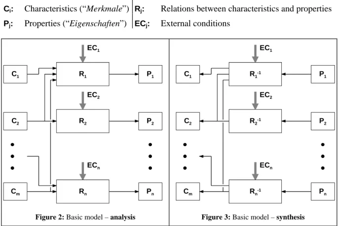
In the PDD approach the two main relations between characteristics and properties are mod-elled in more detail, in principle following a network-like structure. Figures 2 and 3 show the two basic models for analysis and synthesis, respectively. The expressions used in the figures have the following meaning:
Ci: Characteristics (“Merkmale”) Rj: Relations between characteristics and properties
Pj: Properties (“Eigenschaften”) ECj: External conditions
C1 C2 Cm P1 P2 Pn R1 R2 Rn EC2 EC1 ECn C1 C2 Cm P1 P2 Pn R1-1 R2-1 Rn-1 EC2 EC1 ECn
Figure 2: Basic model – analysis Figure 3: Basic model – synthesis
Once the product is realised (i.e.: the product’s characteristics Ci are physically given), its
properties/behaviour (Pj) can be analysed by measuring and testing (albeit this may be quite
time- and money-consuming sometimes, e.g. when testing/checking the product’s durability). In this case the product itself is the representation of the relations (Rj). As is well known,
measuring/testing properties alone does not reveal why the product behaves as it behaves. To answer this question, abstract models, methods and tools have to be established which are ex-actly what the relation-boxes (Rj) in figure 2 stand for.
During the product development process, however, when there is not yet a finished product, its properties can only be analysed by means of appropriate models, methods and tools which represent the relations (Rj) and tell about the influences the relevant characteristics (Ci) have
on the respective properties (Pj), thus predicting the properties depending on characteristics
given at that moment.
Models, methods and tools to realise the relation-boxes could be physical (e.g. [component] prototypes and specified test procedures). But increasingly non-physical models and proce-dures are applied, in many cases mathematical ones. The table shown in figure 4 gives a rough list of different (classes of) methods applied for analysing (predicting) a product’s properties during the development process.
• Guesswork, estimation • Experience
• Customer interrogation
• Physical tests/experiments with – models, mock-ups
– individual components – (complete) prototypes
• Tables, diagrams (formalised experience and/or experimental knowledge)
• Conventional/simplified calculations • Computer tools, e.g.
– model-based, numerical solutions – rule-based
– “fuzzy”
– semantic/neural networks – case-based reasoning • ...
Figure 4: Methods and tools to support (engineering) analysis
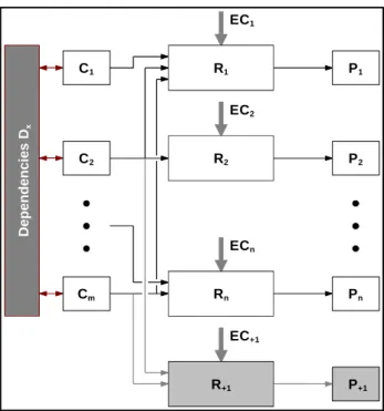
The basic model according to figure 2 needs two additions which are particularly important in the context of “real-life” development/design processes and their computer support (figure 5): • A product may have more properties than the ones originally considered or even
re-quired. In PDD they are called “additional properties” (Rj+). In principle, these may or
may not be relevant for the product, and if they are, they can be regarded either useful or – unfortunately more often – harmful/disturbing. In case that additional properties are considered disturbances, their suppression/diminishing becomes a new required property.
Figure 5: Additional properties and internal relations (constraints) between characteristics
• Very often certain dependencies between different characteristics of a product have to be considered – geometric (“same diameter as ...”), spatial (“ele-ment B parallel to A”), but also con-cerning fit, surface and material para-meters, or even conditions of existence (“component A requires existence of B”). In PDD they are called “Dependen-cies between characteristics” (Dx). In a
mathematical sense these are constraints which reduce the degrees of freedom in a design. As is well known, some spatial as well as geometrical dependencies can be captured and administered by today’s parametric CAD-systems.
Synthesis (figure 3) is formally “just” the inversion of analysis (figure 2): Based on given (re-quired) properties (Pj) the product’s characteristics (Ci) are to be determined. While in biology
the “products” (creatures) themselves even during their lifetimes somehow seem to have the ability to modify their characteristics (e.g. structure, geometry, material) according to changed requirements (required properties), in the technical world we are still very far away from con-cepts like this. Even new approaches such as “adaptronics” stand for much simpler concon-cepts. Therefore, the only way to do synthesis in engineering is to use “inverted relation-boxes” (Rj-1) according to figure 3 which stand for appropriate synthesis methods and tools. These are
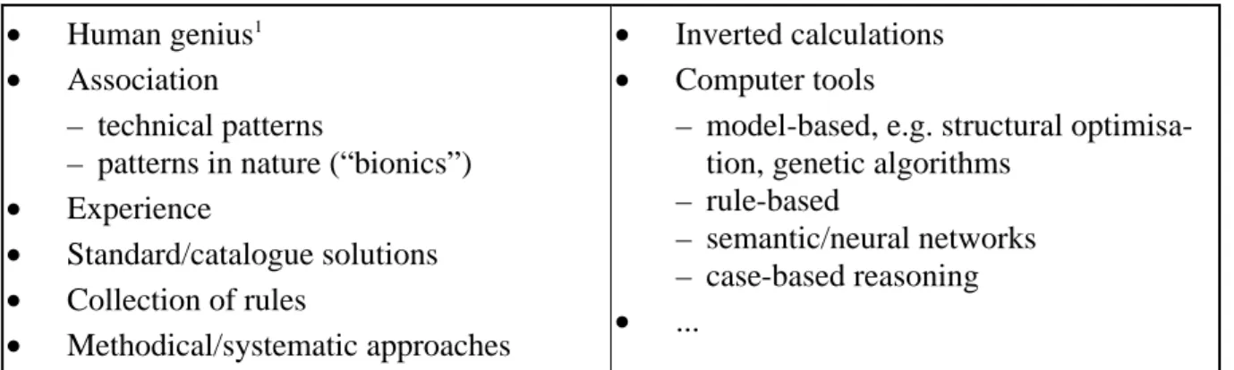
sometimes, but by no means always based on models in the scientific sense. The table shown in figure 6 gives a rough list of different (classes of) methods that can support synthesis, i.e.
P1 P2 Pn R1 R2 Rn EC2 EC1 ECn P+1 R+1 EC+1 Dependencies D x C1 C2 Cm
which can help to determine a product’s characteristics from (required) properties during the development process.
• Human genius1 • Association
– technical patterns
– patterns in nature (“bionics”) • Experience • Standard/catalogue solutions • Collection of rules • Methodical/systematic approaches • Inverted calculations • Computer tools
– model-based, e.g. structural optimisa-tion, genetic algorithms
– rule-based
– semantic/neural networks – case-based reasoning • ...
Figure 6: Methods and tools to support (engineering) synthesis
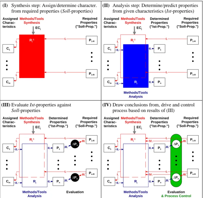
Based on the considerations on the new approach to modelling products, now the conse-quences for the modelling of product development processes are introduced. The product de-velopment process can be seen as an activity which, in principle (“strategically”), follows the synthesis model according to figure 3, but has in between (“tactically”) many analysis steps according to figure 2. During the process – in every synthesis step – ever more characteristics of the product are assigned and determined, in parallel – by means of the analysis steps – ever more and ever more precise knowledge of the product’s properties/behaviour is generated.
Figure 7 gives a schematic overview on this interpretation of the product development proc-ess. To avoid too much complexity, in this figure only one synthesis-analysis-evaluation cycle is shown (which, of course, is closely related to the so-called TOTE-scheme described in [Ehrl-95]). Therefore, the growing number of characteristics and known properties from one cycle to the next can not be demonstrated directly, but should be borne in mind (there is one figure with this focus in [WeWe-01]).
The typical product development process usually starts with a list of requirements. This list is in PDD represented by the required properties (PRj, Soll-properties). The design team decides
on the first major characteristics (Ci) of the future design (synthesis), e.g. by adopting partial
solutions (solution patterns) from previous designs. In the next step the current properties (Pj,
Ist-properties) of the design are analysed, based on the characteristics currently assigned. The results of this analysis are evaluated against the required properties, the result of the compari-son (∆Pj) representing the shortcomings of the current design. The designer or design team
will now draw conclusions on how to proceed, the “gap” between Soll- and Ist-properties thus being the actual driver of the development process. The next cycle of the product develop-ment process (not shown in figure 7) starts with another synthesis step, i.e. the modification of existing or creation of additional characteristics, followed by another analysis step, an evalua-tion and so on.
The product development process terminates when
• all characteristics needed for manufacturing and assembly of the product are assigned, • all (relevant) properties can be determined/predicted
• with sufficient safety and accuracy, and
• all determined/predicted properties meet (i.e.: are close enough to) the required proper-ties.
1 The same as (quick) association?
(I) Synthesis step: Assign/determine character. from required properties (Soll-properties)
Rj-1 ECj P1-R Pn-R C1 Cm Required Properties ("Soll-Prop.") Assigned Charac-teristics Methods/Tools Synthesis I. I. I. I.
(II) Analysis step: Determine/predict properties from given characteristics (Ist-properties)
P1 Pn Rj-1 ECj P1-R Pn-R C1 Cm Required Properties ("Soll-Prop.") Assigned Charac-teristics Determined Properties ("Ist-Prop.") Methods/Tools Analysis Methods/Tools Synthesis Rj I. I. II. II. I. I. II. II.
(III) Evaluate Ist-properties against Soll-properties P1 Pn Rj-1 ECj P1-R Pn-R C1 Cm Required Properties ("Soll-Prop.") Assigned Charac-teristics Determined Properties ("Ist-Prop.") Evaluation Methods/Tools Analysis Methods/Tools Synthesis ∆Pn ∆P1 Rj I. I.
II. II. III.
III.
I. I.
II. II. III.
III.
(IV) Draw conclusions from, drive and control
process based on results of (III)
P1 Pn Rj-1 ECj P1-R Pn-R C1 Cm Required Properties ("Soll-Prop.") Assigned Charac-teristics Determined Properties ("Ist-Prop.") Evaluation Methods/Tools Analysis Methods/Tools Synthesis ∆Pn ∆P1 Rj IV.
& Process Control
I. I.
II. II. III.
III.
IV. I. I.
II. II. III.
III.
Figure 7: Product development process (schematic)
One last aspect of the PDD-process concept introduced here should be mentioned: The term “early phases” has in PDD a quite different meaning than in known design theories and meth-odologies. Here it is not defined with regard to contents of working steps (e.g. in [VDI-2221]: considering functional aspects and solution principles = working in an early phase), but by the number of characteristics and properties which are already known. Then it is easily understandable (and theoretically explainable) that the same properties (function, strength, safety, ergonomics, manufacturing, cost, ...) have to be considered several times in the proc-ess. The difference is that in “early phases”, where only a couple of characteristics are given, very simple methods and tools are required (giving a rough calculation/estimation based on a small number of parameters = characteristics), whereas in “late phases” the focus lies on a calculation/simulation as precise as possible (which is based on and also requires a much big-ger number of parameters!). Accordingly, in the product development process, different meth-ods and tools for the analysis of the same properties have to be provided.
3.
New concept for PDM and PLM
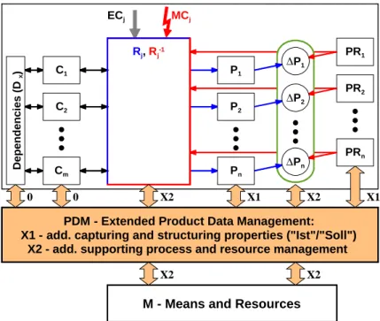
In the following sections, the authors propose a concept for an advanced PDM/PLM-system based on the new PDD approach. This system would expand the capabilities of PDM/PLM beyond the handling of mainly structural data and information (i.e. characteristics and de-pendencies between them, figure 8). It would be able to support the control and the manage-ment of the design process itself.
3.1
Architecture of the proposed PLM-system
The proposed PLM-system is built on the following key elements:
• Today PDM systems mainly, if not entirely handle characteristics (Ci) and some
depen-dencies (Dx) between characteristics (figure 8; state 0).
• As indicated in figure 8, an extended (state X1) PDM/PLM-system would additionally handle prop-erties (Pj, as currently
determined, Ist-proper-ties), as well as required properties (PRj,
Soll-prop-erties). In order to truly support the complete pro-duct lifecycle, the proper-ties of the product while it is in use (PLj,
life-cycle-properties, not shown in figure) could also be considered. This concept is described in [WeDe-02], but is not elaborated any further in this paper. • The next step (figure 8;
state X2) is adding detailed information about the interdependencies between characteris-tics and properties and how to model them (information about relations Rj and Rj-1). This
given, a structured collection of means (M) and resources necessary to realise these relations Rj and Rj-1 (persons, methods, knowledge sources, procedures, [computer-]
tools, etc.) can be managed by the (extended) PDM/PLM-system, in order to trigger and support analysis and synthesis steps with regard to the particular situation [Gero-98]. 3.1.1 Characteristics (Ci), properties (Pj) and required properties (PRj)
These classes of entities are the main repository for the product information.
The list/table/object class of characteristics (Ci) must contain information about or references
to:
• Characteristics (classification, identification, appropriate attributes), including geometry, if applicable
• Currently assigned values of characteristics, plus “rigidity” attribute (unknown/prelimin-ary/fixed) Rj, Rj-1 ECj PRn PR1 PR2 P1 P2 ∆P1 ∆P2 Pn ∆Pn MCj C2 Cm C1 Dependencies (D x )
PDM - Extended Product Data Management:
X1 - add. capturing and structuring properties ("Ist"/"Soll") X2 - add. supporting process and resource management
M - Means and Resources
0 0 X2 X1 X2 X1
X2 X2
• Persons/teams responsible for the characteristics
The list/table/object class of properties (Pj, Ist-prop.) provides information/references about:
• Properties (classification, identification, attributes)
• Currently predicted/estimated values (“Ist-value”) of properties, accuracy of prediction • Persons/teams responsible for the property
The list/table/object class of required properties (PRj, Soll-properties) includes:
• Required properties (classification, identification, attributes) • Ideal values and/or allowed ranges of the required properties • Weight factor of each property
• Accuracy necessary for the determination of each property 3.1.2 Relations (Rj)
The relations are the main element for the modelling and show the interdependencies between the characteristics (Ci) and the properties (Pj). They describe how the analysis and the
synthe-sis take place. The extended PDM-system according to figure 8 must be able to manage main information elements about these relations:
• Analysis methods/tools to predict/verify the properties, based on the values of related characteristics
• Synthesis methods/tools to assign or modify appropriate values of characteristics, based on required properties (Soll-properties) and differences between those and the properties achieved in the preceding design cycle (current Ist-properties)
• Reference to means/resources used for analysis and synthesis, i.e. people, methods, knowledge sources, procedures, (computer-) tools
3.1.3 Set of dependencies (Dx)
The set of dependencies (Dx) describes constraints and relations between characteristics
(geo-metric, spatial, but also concerning fit, surface and material parameters, or even conditions of existence). They act much like parametric constraint management already available in modern CAD-systems, but in an extended manner. Additionally, the dependencies should manage the variants by keeping track which characteristic and, thus, which variant of a part is necessary (or forbidden!) in a certain variant of the solution.
3.1.4 Means and resources (M)
The structured collection of means and resources contains information about people, methods, knowledge sources, procedures, (computer-) tools, and best practices which are needed for the analysis and synthesis process. This collection has close links to the relations (Rj, Rj-1) which
have to utilise certain means/resources to perform particular analysis and synthesis steps. At the same time it is linked to the evaluation of differences between currently determined and required properties (between Ist- and Soll-properties), because the “gap” between them de-termines which of the means/resources is required next.
3.2
Functionalities and advantages of the proposed PLM
Design process and project management/control
During the last years, companies have been trying to streamline their businesses by planning and remodelling the processes and procedures implied. These activities of Business Process Re-Engineering (BPR) focused mainly on the financial and administrative areas. Today, com-panies start to shift or enlarge their focus and also place great emphasis on the planning and (re-) structuring of the design and engineering processes. Each step is computed and the proc-ess is graphically visualised by box diagrams, the boxes being the design task or responsible entities and the connecting lines between the boxes the flow of information and results. By attaching the expected time necessary to complete each step, it is easy to calculate – at least in theory – the critical path and the total time needed for the entire process. Process models of this type can also handle iterations, but the place, the time, the duration and numbers of itera-tions must be known (or guessed) in advance and are fixed once the process model is com-pleted. The development process is driven by milestones, deadlines and fixed procedures. Obviously, models of this type are inflexible, thus making it difficult to react to unexpected delays, iterations or challenges as they occur in real-life product development processes. The authors claim that a PDM-/PLM-system based on the new PDD approach could provide a highly flexible, dynamic process control. This system would handle characteristics (Ci),
rela-tions (Rj), current properties (Pj) and required properties (PRj) separately. As shown in figure
7 and explained in the text, the key element is that the development process in PDD is driven by the continuous evaluation of current properties (Ist-properties) against required properties (Soll-properties) and its results (∆Pj). A PDM/PLM-system following this concept would
as-sist the designer by suggesting possible persons, methods, procedures or tools from the list of means/resources (M) which are mapped to the specific task.
Once a resource has been used for analysis or synthesis, a reference to that resource is at-tached to the relation (Rj), corresponding to the specific property. This “history” of
means/resources used for particular analysis or synthesis steps, makes the design process traceable. Thus, for future analysis or synthesis steps of a certain property first the previously used resources are addressed and secondly, if these resources can not satisfactorily solve the problem, resources from the general resource list would be allocated.
This stream of synthesis, analysis and evaluation cycles goes on until the “gap” between Soll- and Ist-properties is closed (or at least brought to a minimum, ∆Pj è 0). While this procedure
is implicitly existent in the head of every designer, the proposed PDM/PLM-system would make it explicit and comprehensible by guiding and supporting the alternations between syn-thesis and analysis as well as the completion of all steps by providing and controlling the re-quired means/resources (see figure 8).
Further advantages of the proposed PDM/PLM such as identifying design degrees of freedom, enhancing co-operative work/Simultaneous Engineering, integration of CAx tools and design re-use are described in [WeWD-02].
4.
Summary
Property Driven Design/Development (PDD) is a new approach which focuses on the separate handling of characteristics and properties. Properties are divided into required properties (Soll-properties) on the one hand and, at each stage of the development process, into currently determined properties (Ist-properties) on the other hand. The continuous evaluation of
Soll-properties against Ist-Soll-properties shows the shortcomings of the current design and is the actual driver of the development process.
The interdependencies between characteristics and properties are formally described by rela-tions which can be realised in many different ways, but all need certain means and resources (persons, methods, knowledge sources, procedures, [computer-] tools, etc.).
A PDM/PLM-system based on the PDD approach handles characteristics, relations, currently determined properties and required properties separately. It guides the designer by explicitly capturing the flow of analysis and synthesis cycles. The system also handles means and re-sources necessary for the performance of analysis and synthesis steps.
Such a PDM/PLM-system would show the interdependencies between characteristics and properties, it would thus show how a change of the characteristics will affect the properties. With the additional information about the means/resources available, it can support the devel-opment process or even contribute to its control.
References
[Ehrl-95] Ehrlenspiel, K.: Integrierte Produktentwicklung. Hanser, München, 1995. [Gero-98] Gero, J.S.: Towards a Model of Designing Which Includes its Situatedness.
Universal Design Theory, Shaker, Aachen, 1998, p. 47-55.
[Hubk-73] Hubka, V.: Theorie der Maschinensysteme. Springer, Berlin, 1973 (1. ed.). [Hubk-84] Hubka, V.: Theorie technischer Systeme. Springer, Berlin, 1984 (2. ed. of
[Hubk73]).
[HuEd-92] Hubka, V.; Eder, W.E.: Einführung in die Konstruktionswissenschaft. Springer, Berlin, 1992.
[HuEd-96] Hubka, V.; Eder, W.E.: Design Science. Springer-Verlag, Berlin, 1996. [Suh-90] Suh, N.P.: The Principles of Design. Oxford University Press, 1990.
[VDI-2221] VDI-Guideline 2221: Systematic Approach to the Design of Technical Systems and Products. VDI, Düsseldorf, 1987.
[WeDe-02] Weber, C.; Deubel, T.: Von CAx zu PLM - Überlegungen zur Software-Archi-tektur der Zukunft. Proceedings of the VDI-Fachtagung "Informationsverarbei-tung in der Produktentwicklung - Von CAx zu PLM, Stuttgart, 2002, Sec. 5. [WeWD-02] Weber, C.; Werner, H.; Deubel, T.: A Different View on PDM and its Future
Potentials. Proceedings of Design 2002, Dubrovnik/Croatia, University of Zagreb, 2002, Vol. 1, p. 101-112.
[WeWe-01] Weber, C.; Werner, H.: Schlußfolgerungen für „Design for X“ (DfX) aus der Perspektive eines neuen Ansatzes zur Modellierung von Produkten und Produktentwicklungsprozessen. Proceedings of the 12th Symposium "DfX", Erlangen/ Neukirchen, 2001, p. 37-48.
For more information please contact:
Prof. Dr.-Ing. Christian Weber, Dipl.-Ing. Till Deubel Saarland University, Engineering Design/CAD PO Box 15 11 50, D – 66041 Saarbrücken, Germany
Phone: +49 / (0)681 / 302 – 3075; Fax: +49 / (0)681 / 302 – 4858 Email: [email protected]; [email protected]