Copyright © 2013 IJECCE, All right reserved
A Review on Image Processing
Amandeep Kour
Deptt. of CSE, Lovely ProfessionalUniversity, Punjab
Vimal Kishore Yadav
Deptt. of Energy Scienceand Engineering, Indian Institute of Technology,
Bombay, India
Vikas Maheshwari
Deptt. of ECE, School of Engg. and Technology Apeejay Stya University, Sohna,Gurgaon, Haryana, India
Deepak Prashar
Deptt. of ECE, Lovely ProfessionalUniversity, Punjab
Abstract - Image Processing includes changing the nature of an image in order to improve its pictorial information for human interpretation, for autonomous machine perception. Digital image processing is a subset of the electronic domain wherein the image is converted to an array of small integers, called pixels, representing a physical quantity such as scene radiance, stored in a digital memory, and processed by computer or other digital hardware. Interest in digital image processing methods stems from two principals applications areas: improvement of pictorial information for human interpretation; and processing of image data for storage, transmission, and representation for autonomous machine perception. Edges characterize boundaries and edge detection is one of the most difficult tasks in image processing hence it is a problem of fundamental importance in image processing. In this paper investigates different steps of digital image processing.like, a high-speed non-linear Adaptive median filter implementation is presented. Then Adaptive Median Filter solves the dual purpose of removing the impulse noise from the image and reducing distortion in the image.
The Image Processing Toolbox software is a collection of functions that extend the capability of the MATLAB numeric computing environment. The toolbox supports a wide range of image processing operations on the given image.
Keywords - Image Enhancement, Feature Extraction.
I.
I
NTRODUCTIONWith the advent of electronic medium, especially computer, society is increasingly dependent on computer for processing, storage and transmission of information. Computer plays an important role in every parts of today life and society in modern civilization. With increasing technology, man becomes involved with computer as the leader of this technological age and the technological revolution has taken place all over the world based on it. It has opened a new age for humankind to enter into a new world, commonly known as the technological world. Computer vision is a part of everyday life. One of the most important goals of computer vision is to achieve visual recognition ability comparable to that of human [1], [2], [3].Among many recognition subjects, face recognition has drawn considerable interest and attention from many researchers for the last two decades because of its potential applications, such as in the areas of surveillance, secure trading terminals, Closed Circuit Television (CCTV) control, user authentication, HCI Human Computer Interface, intelligent robot and so on. A number of face recognition methods have been proposed [4], [5] and some related face recognition systems have been developed. In this paper the computational model of face recognition, which is fast, reasonably simple, and accurate in
constrained environments such as an office or a household is compared. These approaches have advantages over the other face recognition schemes in its speed and simplicity, learning capacity and relative insensitivity to small or gradual changes in the face image. The first step in face recognition is the acquisition of faces in visual media. Face acquisition for the purposes of Recognition requires not only face detection, but precise alignment prior to matching faces. We perform this alignment automatically through pose estimation and landmark localization.
II. D
IFFERENTA
PPROACHCopyright © 2013 IJECCE, All right reserved working with any data format. Image Processing Toolbox
supports a number of specialized image file formats.
Image as input
:
The system needs some types of images as the input. These images require the process of computer algorithms as per the input image. These computer algorithms yield two types of images from Computer Algorithm: noisy image and magnitude image.Size of images
:
There are two sizes of images that we can use, that are (512 X 512) inches, (256 X 256) inches, and (1024 X 1024) inches.Image file formats
: A Variety of image file formats are available at present. Like TIFF, JPEG, GIF, BMP, etc. We mainly using TIFF and JPEG here, these are explained as follows:-TIFF- stands for Tagged Image File Format. Its extension is recognized both as „tif‟ and „tiff‟. These are the file formats used for storing images, including photographs and line art. It grew to accommodate greyscale images, then colour images. Today, it is a popular format for high-colour-depth images, along with JPEG.
JPEG- stands for Joint Photographic Experts Group. It has „.jpg‟, „jpeg‟ as the allowed extensions. It is the most common format for storing and transmitting photographic images on the World Wide Web and is a commonly used method of compression for photographic images.
Fig.1. .JPG Image Format
Images types
:
Four types of images are there:Intensity images
– An intensity image is a data matrix whose values represent Intensities within some range. For the elements of class uint8 or class uint16 of an intensity image, the integer values lie between (0,255) and [0, 65535], respectively. And if the image is of class double, then the associated values are floating-point numbers. Conventionally, the intensity images with scaled, class double data type have a range of [0, 1]. In MATLAB, an intensity image is stored as a single matrix, with each element of the matrix corresponding to one image pixel.Fig.2. GRAY Image Format
Binary images
- A binary image is a logical array of 0s and 1s. Pixels with the value 0 are displayed as black; pixels with the value 1 are displayed as white. In MATLAB, a binary image must be of class logical that is why the intensity images that happen to contain only 0‟s and 1‟s are not taken as binary images[6].Fig.3. BW Image Format .This gives image in Black and White.
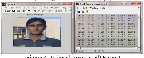
Indexed images
–
An indexed image consists of a data matrix, X, and a Colour map matrix termed as “map”. The “map” is an m-by-3 array of class double containing floating-point values in the range [0, 1]. Its every row specifies the red, green, and blue components of a single colour. For these images pixel values are directly mapped to their corresponding colour map values [7].Figure 4: Indexed Image (red) Format
RGB images
-
An RGB image is also referred as a true- colour image. In MATLAB these images are stored in the form of an m-by-n-by-3 data array that defines red, green, and blue components for each individual pixel. The colour of each pixel is determined by the combination of the red, green and blue intensities stored in each colour plane at the pixel‟s location. Graphics file formats store RGB images as 24-bit images, where the red, green and blue components are 8 bits each. An RGB array can be of class double, uint8, or uint16. In an RGB array of class double, each colour component is a value between 0 and 1. A pixel whose colour components are (0,0,0 ) is displayed as black, and a pixel whose colour components are (1,1,1 ) is displayed as white. The three colour components for each pixel are stored along the third dimension of the data array.Figure 5: RGB Image Format
Copyright © 2013 IJECCE, All right reserved image with a resolution of 640×480 means that it display
640 pixels on each of the 480 rows. Some other common resolution used is 800×600 and 1024×728. Resolution is one of most commonly used ways to describe the image quantity of digital camera or other optical equipment. The resolution of a display system or printing equipment is often expressed in number of dots per inch. For example, the resolution of a display system is 72 dots per inch (dpi) or dots per cm.
Pre and Post-Processing Images
:
Image Processing Toolbox provides reference-standard algorithms for pre- and post processing tasks that solve frequent system problems, such as interfering noise, low dynamic range, out-of-focus optics, and the difference in colourrepresentation between input and output devices.
Image processing operations
:
Image processing operations can be roughly divided into three major categories:A) Image Restoration B) Image Enhancement
C) Remove “noise” from an image D) Remove motion blur from an image. E) Image Compression
F) Image Segmentation G) Feature extraction H) Image transformation
A) Image Restoration: Restoration takes a corrupted image and attempts to recreate a clean image. As many sensors are subject to noise, they results in corrupted images that don‟t reflect the real world scene accurately and old photograph and film archives often show considerable damage.
Thus image restoration is important for two main applications:
a) Removing sensor noise,
b) Restoring old, archived film and images. It is clearly explained in the figure 6 and figure 7.
Fig.6. Original image Fig.7. Image after restoration
B) Image Enhancement
Image enhancement techniques in Image Processing Toolbox enable to increase the signal-to-noise ratio and accentuate image features by modifying the colours or intensities of an image. It can:a) Perform histogram equalization b) Perform de correlation stretching c) Remap the dynamic range d) Adjust the gamma value
e) Perform linear, median, or adaptive filtering
The toolbox includes specialized filtering routines and a generalized multidimensional filtering function that handles integer image types, multiple boundary padding options, and convolution and correlation. Predefined filters
and functions for designing and implementing its own linear filters are also provided.
a) Histogram equalization
:
Its one of the step used in image processing so that the image [8] contrast through should be uniformed. Image after histogram equalizationFig.8. Histogram Equlization
b) De-correlation Stretch
:
The de-correlation stretch is a process that is used to enhance (stretch) the colour differences found in a colour image. The method used to do this includes the removal of the inter-channel correlation found in the input pixels; hence, the term "de-correlation stretch"The purpose of this document is to explain:
a) The conditions that normally appear in multispectral data that indicate that colour enhancement is needed, b) How a de-correlation stretch addresses those needs, c) How a de-correlation stretch works, i.e., computationally, what steps are performed,
d) What the limitations are to this approach.
c) Remap the dynamic range
:
In image processing, computer graphics, and photography, high-dynamic-range imaging (HDRI or just HDR) is a set of techniques that allow a greater dynamic range of luminance between the lightest and darkest areas of an image than current standard digital imaging techniques or photographic methods. This wide dynamic range allows HDR images to more accurately represent the range of intensity levels found in real scenes, ranging from direct sunlight to faint starlight.[9]The two main sources of HDR imagery are computer renderings and merging of multiple photographs, the latter of which in turn are individually referred to as low dynamic range (LDR)[10] or standard dynamic range (SDR)[11] photographs.
Tone-mapping techniques, which reduce overall contrast to facilitate display of HDR images on devices with lower dynamic range, can be applied to produce images with preserved or exaggerated local contrast for artistic effect. Merged to HDR then reduced to LDR
Fig.9. Local tone mapping Fig.10. Simple contrast reduction
Copyright © 2013 IJECCE, All right reserved probably already know that a pixel can have any 'value' of
Red, Green, and Blue between 0 and 255, and you would therefore think that a pixel value of 127 would appear as half of the maximum possible brightness, and that a value of 64 would represent one-quarter brightness, and so on. Well, that's just not the case, I'm afraid.Here's an example of the effect that a change in gamma can have on the appearance of an image.
Fig.11. (a) Left (b) Centre (c) Right
On the left is the image as it might appear on an un-corrected monitor. The centre image should look right on a monitor with a gamma of around 1.8, and lastly; Right-hand image is how a system with a linear response
[gamma of 1.0] might display the image.
Notice how the colour saturation and hue change with the gamma?
What this means is that if your monitor gamma isn't set correctly, then you haven't a hope of seeing colours and tones the way that they'll appear on other people's monitors; and they won't see your images the way that you intended either.
e)
Median Filter
: Median filtering is a non-linear, low-pass filtering method, which you use to remove "speckle" noise from an image. A median filter can outperform linear, low-pass filters on this type of noisy image because it can potentially remove all the noise without affecting the "clean" pixels. Median filters remove isolated pixels, whether they are bright or dark.Fig.12. Implementation of a 3 × 3 median filter window
C)
Remove “noise” from an image
: Noise is considered to be any measurement that is not part of thephenomena of interest. Noise can be generated within the electrical components of the Input amplifier (internal noise), or it can be added to the signal as it travels down the input wires to the amplifier (external noise). There are various types of noises available in MATLAB: „Gaussian‟, „Poisson‟, and „Speckle‟, „localvar ‟, „Salt & pepper (Median). Noise is added to the input images to check their various parameters. Here noise is removing from image.
D)
Deblurring Images
: Image Processing Toolbox supports several fundamental deblurring algorithms, including blind, Lucy-Richardson, Wiener, and regularized filter de-convolution, as well as conversions between point spread and optical transfer functions. These functions help correct blurring caused by out-of-focus optics, movement by the camera or the subject during image capture, atmospheric conditions, short exposure time, and other factors. All deblurring functions work with multidimensional images.E)
Image Compression
: To store these images, and make them available over network (e.g. the internet), compression techniques are needed. Image compression addresses the problem of reducing the amount of data required to represent a digital image.Need for compression
The following example illustrates the need for compression of digital images.
a) To store a colour image of a moderate size, e.g. 512×512 pixels, one needs 0.75 MB of disk space. b) A 35mm digital slide with a resolution of 12 μm
requires 18 MB.
c) One second of digital PAL (Phase Alternation Line) video requires 27 MB.
An[14] image, 1024 pixel×1024 pixel×24 bit, without compression, would require 3 MB of storage and 7 minutes for transmission, utilizing a high speed, 64 Kbits/s, ISDN line. If the image is compressed at a 10:1 compression ratio, the storage requirement is reduced to 300 KB and the transmission time drop to less than 6 seconds. Types of compression [14]:-
Lossless coding techniques:
a) Run length encoding b) Huffman encoding c) Arithmetic encoding d) Entropy coding e) Area coding
Loss coding techniques:
a) Predictive coding
b) Transform coding (FT/DCT/Wavelets)
Copyright © 2013 IJECCE, All right reserved a) Original image b) result of k-means segments
c) final segments after segmentation Fig.13. Perceptual Image Segmentation Algorithm
a) Threshold segmentation techniques b) Edge detection segmentation techniques.
Edge detection:
Several methods of edge detection exist in practical. The procedure for determining edges of an image is similar everywhere but only difference is the use of masks. Different types of masks can be applied such as
a) Sobel b) Prewitt c) Kirsch d) Canny
Motivation behind Edge Detection:
The purpose of detecting sharp changes in image brightness is to capture important events and changes in properties of the world. For an image formation model, discontinuities in image brightness are likely to correspond to:-a) Discontinuities in depth
b) Discontinuities in surface orientation c) Changes in material properties d) Variations in scene illumination
a) Sobel mask method b) Canny mask method Fig.14. Edge-detection
Thresholding
:
Once we have computed a measure of edge strength (typically the gradient magnitude), the next stage is to apply a threshold, to decide whether edges are present or not at an image point. The lower the threshold, the more edges will be detected, and the result will be increasingly susceptible to noise and detecting edges of irrelevant features in the image. Conversely a high threshold may miss subtle edges, or result in fragmented edges.G)
Feature Extraction [12]:
Two methods are discussed herea) To extract features of a face at first the image is converted into a binary. From this binary image the centroid (X, Y) of
The face image is calculated using equation 1 and 2.
𝑿 = 𝒎𝒙 𝒎 (1)
𝒀 = 𝒎𝒚 𝒚 (2)
Where x, y is the co-ordinate values and m=f(x,y)=0 or1. Then from the centroid, only face has been cropped
and converted into the gray level and the features have been collected.
b) Gabor filter-
It is also one of the methods to extract feature from image. Will give image features in eight different angles and at five different frequencies. A Gabor filter is a linear filter whose impulse response is defined by a harmonic function multiplied by a Gaussian function. Because of the multiplication-convolution property (Convolution theorem), the Fourier transform of a Gabor filter's impulse response is the convolution of the Fourier transform of the harmonic function and the Fourier transform of the Gaussian function [13]. A Gabor filter can be applied to images to extract feature aligned at particular orientation. The useful parameters of a Gabor filter are orientation and frequency. The Gabor filter is thought to mimic the sample cells in the visual cortex [8]. Here a Gabor filter bank is implemented on face images with 8 different orientation and 5 different frequencies (in Gabor wavelet transformation is done by convolution of the image with the 40 Gabor filters). Formally the Gabor filter is a Gaussian (with variances Sx and sy along x and y-axes respectively) and is described by theEquation: -Gabor filter = G(x,y,𝜃,f) 𝐺 = 𝑒𝑥𝑝 −1
2 𝑥′
𝑠𝑦 + 𝑦
𝑠𝑦 × cos 2 × 𝜋 × 𝑥′ (3)
𝑥′= 𝑥 ∗ cos 𝜃 + 𝑦 ∗ sin 𝜃
𝑦′ = 𝑦 ∗ cos 𝜃 − 𝑥 ∗ sin 𝜃 f: frequency
𝜃: The orientation G: Output filter
Gabout: Output filtered image
Fig.15. Gabor filter of five frequencies and 8 orientations h(x, y) : s(x, y)g(x, y)
s(x, y) : Complex sinusoid
Copyright © 2013 IJECCE, All right reserved compression. Image Processing Toolbox provides several
image transforms, including DCT, Radon, and fan-beam projection. It can reconstruct images from parallel-beam and fan-beam projection data (common in tomography applications). Image transforms are also available in MATLAB and in Wavelet Toolbox (available separately).
III.
R
ESULT ANDD
ISCUSSIONThe Image processing helps in the improvement of pictorial information, which is easily interpreted by human and image can easily stored, transmitted and represented for autonomous machine perception. The different steps of digital image processing can be done by implementation of a high-speed non-linear Adaptive median filter .It also solve the dual purpose of removing the impulse noise from the image and reducing distortion in the image. The
capability of the MATLAB numeric computing
environment can be extended by Image Processing Toolbox.
IV.
C
ONCLUSIONHere we discuss different steps of image processing, from the beginning where you taken simple image to every processing steps of digital image processing. This discussion evaluates the optional steps for each stage. In this paper the fast, simple and accurate computational model of face recognition is given. These approaches have advantages over the other face recognition schemes in its speed and simplicity, learning capacity and relative insensitivity to small or gradual changes in the face image the best you consider according to our objective .Like, different edge detection process is given here and each one have different characteristic. Similarly for feature extraction here two processes used name centriod (X, Y) and gabor filter technique. Whichever is considered is depend upon on our objective.
IV. F
UTURES
COPEWe can implement the best algorithm to find best result in according with noised, blurred and many unwanted error contain in image. In image an important part is the compression. Image compression reduces the amount of data required to represent the image by using different transform so its important to reduce the data size
R
EFRENCES[1] Jain, Fundamentals of Digital Image Processing, Prentice-Hall Inc., 1982.
[2] E. Trucco, and A. Verri, Introductory Techniques for 3-D
Computer Vision, Prentice-Hall Inc., 1998.
[3] L. G. Shapiro, and G. C. Stockman, Computer Vision, Prentice-Hall Inc., 2001.
[4] R. Chellappa, C.L. Wilson, S. Sirohey (1995), “Human and machines recognition of faces: a survey”, Proc.IEEE 83(5): 705-740.
[5] A.Samal and P.A.Iyengar ,Automatic recognition and analysis of
human faces and facial, 1992.
[6] M Sonka., V.Hlavac, R. Boyle: “Image Processing, Analysis and Machine Vision”. Thomson, 2008
[7] William, K. Pratt, Digital Image Processing, Fourth Edition, A John Wiley & Sons Inc. Publication, pp.465-529, 2007. [8] Matlab Help Manual.
[9] E. Reinhard; G.Ward,; S. Pattanaik,; P. Debevec, (2006). High dynamic range imaging: acquisition, display, and image-based
lighting.2006
[10] J. Cohen and C. Tchou and T. Hawkins , P. Debevec ,S. J. Gortler and K. Myszkowski. ed. "Real-Time High Dynammic Range Texture Mapping". Proceedings of the 12th Euro
graphics Workshop on Rendering Techniques (Springer): E.
(2001). 313–320.
[11] V. Vonikakis and I. Andreadis “. Second Pacific Rim Symposium (PSIVT) 2007”, Santiago, Chile, December 17–19,
2007.
[12] S.Venkatesan andM.Karnan:“Edge and Characteristics Subset Selection in images using ACO, Computer research and Developemnt 2010” Second International Conference
(ICCRD)7-10 ,May 2010,Page 369-372
[13] J. R. Movellan, “Tutorials on Gabor Filters”, pp.1-20, GNU
Free documentation License 1.1,Kolmogorv Project,2002.
[14] R.C. Gonzalez & R. E. Woods,Digital Image Processing, Addison-Wesley Co.,1991.
[15] A. R. Gillespie, A. B Kahle and R. E. Walker (1986), Colour enhancement of highly correlated images. I. Decorrelation and
HIS contrast stretches, Remote Sensing of Environment,
20:209-235.
A
UTHOR’
SP
ROFILEAmandeep Kour
passed B.E degree in information technology from Mahant Bachittar Singh College of Engineering and Technology, Jammu University,India in the year 2009. She received the diploma in Intrnational cross cultural research and human resource management from The Bussiness School, Jammu university, India in the Year 2010. Presently she is persuing her M.Tech in computer Science from Lovely Professional University , Jalandhar,india.Her research intrest includes Face recognition using Template Matching.Her 2 paper is accepted in International Journals and 1 paper in International Conference(IEEE).