http://dx.doi.org/10.9717/JMIS.2017.4.4.179
179
I. INTRODUCTION
As the demand for video quality has increased for many years now, new video codec standards have also been developed with improved compression performance. Most famous standards such as MPEG-2, MPEG-4 AVC/H.264 and HEVC were standardized by either ISO/IEC Moving Picture Experts Group (MPEG) and ITU-T Video Coding Experts Group (VCEG) under royalty-bearing intellectual property rights policy. Recently, the need for royalty-free video codec has been coming up with interesting situations: most patents of core technologies adopted in widely-used standards (e.g., MPEG-2) have either expired or will be expiring soon; many codec-related companies would like to support royalty-free codec; and studies of royalty-free codecs have recently been receiving attention in the literature [1-5].
Recognizing the diversified needs of the Internet, MPEG issued the Call for Proposals (CfP) for Internet Video Coding (IVC) technologies [6]. The IVC standard should
achieve three goals: 1) the baseline profile will be granted in a free of charge license (i.e., Type-1 license) by patent owners according to the ISO/IEC Common Patent Policy [7], 2) the baseline profile will achieve better compression performance than MPEG-2 and be comparable to AVC Baseline Profile, and 3) the complexity will be feasible for real-time encoding/decoding on generally available personal computers and mobile devices [6]. Responding to the CfP, several influential industry leaders and universities proposed three codecs [8]: Web Video Coding (WVC), Video Coding for Browsers (VCB) and IVC.
By far, MPEG experts investigated and verified that the coding efficiency of IVC is better than that of AVC Constrained Baseline Profile and is even comparable to AVC High Profile in terms of subjective quality [8], showing additional results that IVC is mostly better than WVC and VCB. With these diligent efforts, the preliminary of the final draft of international standard (FDIS) version of IVC was published in January 2017. There exists, however, one important issue that needs resolving: the decoding complexity problem for various real-time internet applications (e.g., video chat and internet streaming).
Complexity Analysis of Internet Video Coding (IVC) Decoding
Sang-hyo Park
1,
Tianyu Dong
2and Euee S. Jang
2,*Abstract
The Internet Video Coding (IVC) standard is due to be published by Moving Picture Experts Group (MPEG) for various Internet applications such as internet broadcast streaming. IVC aims at three things fundamentally: 1) forming IVC patents under a free of charge license, 2) reaching comparable compression performance to AVC/H.264 constrained Baseline Profile (cBP), and 3) maintaining computational complexity for feasible implementation of real-time encoding and decoding. MPEG experts have worked diligently on the intellectual property rights issues for IVC, and they reported that IVC already achieved the second goal (compression performance) and even showed comparable performance to even AVC/H.264 High Profile (HP). For the complexity issue, however, there has not been thorough analysis on IVC decoder. In this paper, we analyze the IVC decoder in view of the time complexity by evaluating running time. Through the experimental results, IVC is 3.6 times and 3.1 times more complex than AVC/H.264 cBP under constrained set (CS) 1 and CS2, respectively. Compared to AVC/H.264 HP, IVC is 2.8 times and 2.9 times slower in decoding time under CS1 and CS2, respectively. The most critical tool to be improved for lightweight IVC decoder is motion compensation process containing a resolution-adaptive interpolation filtering process.
Key Words: Decoder complexity, MPEG IVC, AVC/H.264, Complexity analysis, Type-1 codec.
Manuscript received November 24,2017; Revised December 6, 2017; Accepted December 9, 2017. (ID No. JMIS-2017-0040) Corresponding Author (*): Euee S. Jang, Department of Computer Science, Hanyang University, Seoul, South Korea, Tel: 82-2-2220-1086, E-mail: [email protected].
1Communications & Media R&D Division, Korea Electronics Technology Institute, Gyeonggi-do, South Korea, E-mail:
2 Department of Computer Science, Hanyang University, Seoul, South Korea, E-mail: [email protected];
180 In this paper, we briefly review IVC technologies
focusing on their differences from conventional video codecs and analyze the decoder modules in terms of computational complexity. We measure time complexity (i.e., running time) to precisely investigate the complexity of IVC coding tools just as other conventional video codecs have been investigated in the literature ([9-11]). In addition, we evaluate how much an IVC-specific tool affects decoding time by turning on/off those tools. Through the experimental results, we present how complex an IVC decoder is and which module is critical in IVC decoding. In addition, we compare the decoding complexity of IVC to that of AVC/H.264 Baseline and High Profiles, which are commonly used in many streaming applications. With the results from the analysis of IVC decoding, it would be helpful for the reader to derive the time complexity estimation for a variety of processors and to optimize the decoding speed of IVC.
The remaining sections are organized as follows. Section 2 briefly describes the different features of IVC decoding from other existing video codecs. Section 3 identifies the time complexity of IVC decoder with experimental analysis. Section 4 shows experimental results of comparison between IVC and a widely-used codec AVC/H.264 [12] in terms of time complexity. Finally, Section 5 concludes this paper.
II. DISTINCTIVE FEATURES OF
INTERNET VIDEO CODING (IVC)
DECODER
IVC is a codec with a similar coding structure to MPEG-2 standard [13] but enhanced with several effective techniques. Some contributors declared their own patented techniques to be Type-1 for IVC codec. Other contributors mined prior art techniques that have expired or revealed in the literature without patents. In other cases, contributors mined prior art techniques, which means that the techniques have expired or revealed in the literature without patents. In big picture, as in conventional video codecs, an IVC bitstream should be decoded through an inverse transform/quantization process (if needed according to the syntax of each macroblock), motion compensation and entropy coding. Except for group of pictures (GOP) layer, IVC has the same hierarchical layer as MPEG-2, which consists of sequences, pictures, slices and macroblocks in layers. However, since many new and old (i.e., prior art) techniques have been adopted in IVC to gain compression performance further, those different aspects are given in the remaining subsections with emphasis on the basic principle. The detailed information of how to parse bitstream, how to interpret the coded symbols and how to reconstruct video
will be fully specified by the FDIS of IVC [14], as usual with popular video coding standards.
2.1. Frame Type and MB Type
There are three picture types in IVC: intra-coded frame (I-frame), predictive-coded frame (P-frame) and bidirectional predictive-coded frame (B-frame). Since IVC adopted a prior art technique that uses multiple reference
frames, blocks of P frame can refer not only to the most recent P-frame, but also to earlier P-frames or I-frame. IVC has been developed with two coding configuration targets: random access and low-delay scenarios. For the random access scenario, IVC takes IBBP coding structure. As described in Fig. 1, B-frame can only refer to the nearest I- or P-frame, while P-frame can refer to multiple previous P-frames or I-frames—if stored in the reference frame buffer.
Fig. 1. An example of IBBP coding structure in IVC. Arrows represent where each frame can refer for inter-prediction.
For low-delay applications, IVC bitstream can be encoded with IPPP coding structure. In this case, a P-frame must refer to one of the previous frames of which distances from the current frame were pre-defined. IVC has an additional P-frame type, called non-reference P-frame, as a sub-type that will not be delivered or used to reference frame buffers for coding efficiency.
Macroblock (MB) is partitioned by a quadtree-based approach within 16 x 16 pixels as shown in Fig. 2. Among those five partitions, the inter-predicted block can be coded by four partitions {16 x 16, 8 x 16, 16 x 8 and 8 x 8}; on the other hand, intra-predicted block can be coded by three squared partitions {16 x 16, 8 x 8 and 4 x 4}. According to the MB partition type, each block can be predicted by various modes and transformed/quantized with different kernel sizes separately, which is described in the following subsections.
2.2. Inter-Prediction (Prediction Modes and Motion Accuracy)
http://dx.doi.org/10.9717/JMIS.2017.4.4.179
181 prediction mode is an intriguing mode that makes an imaginary block by combining two reference blocks in previous frames (the detailed process was presented in [15]). Thus, this last mode needs additional motion compensation process, which can overweigh decoder complexity.
In B-frame, the basic concept of forward prediction and skip modes are shared with P-frame. In addition, backward and bidirectional prediction (also called symmetrical) modes are allowed in B-frame. Backward mode predicts the current block through future reference frames. On the other hand, Bidirectional mode refers to both past and future reference frames and make two blocks, one which is suitable enough to predict the current block.
IVC also increased motion accuracy by adopting interpolation filtering technique that enables it to generate half-/quarter-pels. The interpolation filter in IVC is distinguished from other recent video codecs due to a variable filter tap size depending on video resolution. It varies within 4-, 6- and 10-tap size for luma component, but for chroma, a 4-tap size is used. Undoubtedly, the larger filter tap size is, the heavier the burden on decoder complexity becomes.
Fig. 2. MB partition types and the block size of each type in IVC.
2.3. Intra-Prediction
The concept of intra-prediction—predicting pixels through information in the same frame—was already present in MPEG-2 [13]; however, in IVC, the intra-predicted block can exist in P- or B-frames as well, of which this has been widely used in recent video codecs. Instead of having only DC mode as in MPEG-2, intra-prediction in IVC has several additional modes depending on MB partition and on color component. For luma component, there are one DC and four directional modes (i.e., horizontal, vertical, down left (↙) and down right (↘)) based on the availability of upside and/or left side neighbor samples. These five modes are supported in 16 x 16, 8 x 8 and 4 x 4 MB partitions.
On the other hand, there are totally four modes (i.e., DC, horizontal, vertical and plane) for chroma components supported in an 8 x 8 MB partition only. Among the four
modes, DC/horizontal/vertical modes for chroma intra-prediction are operated in the same way as those for luma, but the last mode is different. The plane mode takes neighbor samples of both directions (upside and left side samples) and does summation, shift, and clipping operations with them. The plane mode might place a burden on the decoder complexity due to those operations since other directional modes could directly assign neighbor pixels to the target pixels without those additional operations.
2.4. Transform and Quantization
Integer discrete cosine transform technique is used with quadtree-based variable kernel size [16] and the supported sizes for IVC are 16 x 16, 8 x 8 and 4 x 4. Unless the prediction mode of a block is encoded with skip mode, an inverse transform should be performed on the premise that this block has been quantized. In the current ITM, a butterfly structure is used, supporting a 1-D 8-point forward transform and proper approximation is performed to generate rational numbers for irrational numbers in this structure.
The order of transform and quantization process at decoder is as follows. The input values should be scanned in a zigzag order and the scanned values should be transformed inversely. Afterwards, the inverse-transformed values are to be dequantized according to a given quantization parameter (QP) value. Dequantization table and associated shift table are described in the FDIS of IVC [14].
2.5. Arithmetic Entropy Coding
For the entropy coding, IVC uses logarithmic domain arithmetic coding which takes the following steps: 1) initialization process of context model, 2) binarization process if the syntax element is non-binary, and 3) binary arithmetic decoding for bin string (including context model selection if necessary). The arithmetic entropy coder in IVC is logarithmic binary arithmetic coder (LBAC) which avoids multiplication operations and look-up tables. By using LBAC, the decoder can avoid redundant memory costs and path delays caused in context adaptive binary arithmetic coding [17].
2.6. Loop Filter
182 for subjective visual quality. In brevity, weak loop filtering
filters only two pixels per one horizontal or vertical boundary line, normal loop filtering filters four pixels and strong filtering filters six pixels. Surely, the stronger the filtering, the more decoding time is needed. The detailed information on how to filter pixels is described in [8] and the associated parameters such as threshold values are presented in [19].
III. COMPLEXITY ANALYSIS OF
INTERNET VIDEO CODING DECODER
In this section, the complexity of IVC decoder is analyzed using a profiling tool. To analyze the complexity, IVC bitstream files are generated by IVC test model (ITM) 14.0 and then decoded by IVC decoder. To give the associated information in detail, the test material (i.e., video sequences) and test environment to decode bitstream are presented in the following subsection. In addition, specific coding conditions are described, including the parameters used in the encoding process to generate IVC bitstream files. To analyze the complexity of the IVC decoder, a well-known profiling tool—Intel VTune performance analyzer [20]—is used in this paper. Finally, the results of the analysis are described according to the classification of major coding tools so that we could notice which tool is critical in terms of the complexity.
3.1. Analysis Setup
We chose four test sequences from the recommended video sequences specified in the IVC exploration experiment document [21]. The detailed information on each video sequence is shown in Table 1, including the number of frames to be encoded. All the sequences were tested under both constraint set 1 (CS1) and constraint set 2 (CS2) conditions. CS1 and CS2, respectively, are similar to random access and low delay coding structures, the commonly used configurations in recent video codecs. To evaluate the time complexity, the following development environment was employed: quad-core CPUs running at 2.40 GHz, 8 GB random-access memory (RAM) and a 64-bit Windows operating system (OS). Decoding each bitstream file was carried in a single thread and no parallelization techniques were used during decoding.
Table 1. Information on test sequences.
Sequence name Resolution Total frame number FPS
Kimono 1920x1080 240 24
ParkScene 1920x1080 240 24
BasketballDrill 832x480 500 50
PartyScene 832x480 500 50
Describing related encoding conditions specifically is important as the characteristics of bitstream files including decoding complexity can vary depending on the encoding conditions such as quantization parameter. Table 2 shows the general encoding parameters for CS1 and Table 3 shows sequence-specific encoding parameters for CS1. Similarly, Table 4 shows the general encoding parameters for CS2 and Table 5 shows sequence-specific encoding parameters for CS2. In general, the ITM encoder description [19] describes some of the encoding conditions and parameters, but there are few different parameters, such as QP, in this paper. Those different parameters are set to fit the given target range of bitstream size, which was agreed by MPEG experts to conduct visual assessment of Type-1 codecs [22].
Table 2. General encoding conditions and parameters for CS1
Coding
parameter Used value Description
QP Remaining
Frame QPI + 2
QP for P-frames (0-63)
QPB Picture QPI + 5 QP for B-frames (0-63)
FME 1 Fast Motion Estimation
Number
Reference Frames 5
Number of previous frames used for inter motion search
P SubType 0 coding Non-reference P-frame
RDO_Q 1 optimization on quantizationRate distortion (RD)
Multiple HP 1
Low cost
multiple-hypothesis motion
compensation
ABT Enable 1 prediction 16x16 transform and
intra-IF TYPE 1 Adaptive tap
Loop Filter
Disable 0
Disable loop filter in frame header
Table 3. Sequence-specific parameters for CS1.
Sequence Intra
Period QP First Frame Number B Frames
Kimono 8 (24)* 24 2
ParkScene 6 (24)* 27 3
BasketballDrill 13 (52)* 32 3
PartyScene 13 (52)* 35 3
http://dx.doi.org/10.9717/JMIS.2017.4.4.179
183 Table 4. General encoding conditions and parameters for CS2.
Coding
parameter Used value Description
QP Remaining
Frame QPI + 2
QP for P-frames (0-63)
QPB Picture QPI + 5 QP for B-frames (0-63)
FME 1 Fast Motion Estimation
Number
Reference Frames
5 used for inter motion search Number of previous frames
P SubType 1 coding Non-reference P-frame
P SubType Non
Adaptive 0
Non-adaptive non-reference P-frame coding
P Sub QP
Delta0 7 added from QP for P-frames QP for 3rd layer P-frames
P Sub QP
Delta1 3
QP for 2nd layer P-frames added from QP for P-frames
RDO_Q 1 RD optimization on
quantization
Multiple HP 1 hypothesis Low cost multiple-motion compensation
ABT Enable 1 prediction 16x16 transform and
intra-IF TYPE 1 Adaptive tap
Loop Filter
Disable 0
Disable loop filter in frame header
Table 5. Sequence-specific parameters for CS2
Sequence QP First Frame (QP for I-frame)
Kimono 23
ParkScene 23
BasketballDrill 29
PartyScene 33
3.2 Analysis Results and Observation
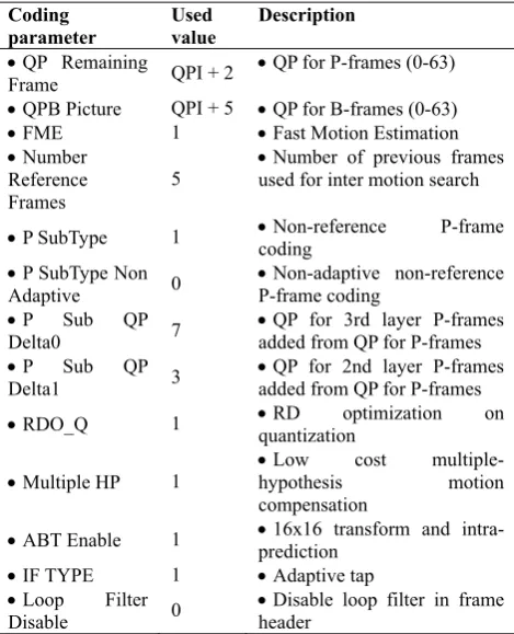
We measured the time consumed by each function using the performance analyzer. We classified those functions used in the decoding into six categories: motion compensation (MC), entropy decoding (ED), intra-prediction (IP), loop filtering (LF), inverse transform/quantization (T/Q) and so on. This classification is a common theme in research on the decoding complexity analysis of recent video codecs including the analysis of HEVC [10] and of AVC/H.264 [9]. Under the CS1 condition, Fig. 3 shows the performance ratio of the six categories of functions in accordance with video resolutions—1920 x 1080 and 832 x 480. The most time-consuming category is MC. This trend has also been seen in other recent video codecs [9-10] because of the highly complex interpolation filtering. The reason that MC consumes most of the decoding time can be explained as follows. Firstly, all the motion vectors in B-frame are
derived by multiplying the distances of frames. Thus, motion vectors can indicate half-pel or quarter-pel not only depending on the motion vector difference (MVD) value, but also depending on the distance. Secondly, multiple-hypotheses prediction modes in P-frame must use interpolation filtering as this mode takes the average value of two motion vectors. Finally, due to the adaptive filter tap size according to the video resolution, the percentage of MC can be increased in low video resolution. If the height of frame is less than 720, the filter size for interpolation filtering will be 10-tap, which is larger than the filter tap size of HEVC. Note that IVC uses the same filter tap size for half-pel and quarter-pel interpolation processes.
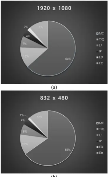
Under the CS2 condition, Fig. 4 shows the performance ratio of the six categories of functions in accordance with video resolutions—1920 x 1080 and 832 x 480. Still, the most time-consuming category is MC under CS2. One of differences of results from CS1 is that the percentage of MC under CS2 further decreased. One possible explanation is that there is no more B-frame in CS2. The other noticeable difference from CS1 is that the percentage of LF is slightly increased. Since CS2 has a special P-frame type, called non-reference P frame, which is usually encoded by much higher QP value than other frames, we guess that those frames tend to need deblocking filtering to compensate for coding errors.
As shown in Fig. 3 and Fig. 4, MC was the most time-consuming category. Thus, we believe that to reduce IVC decoding complexity, interpolation filtering should be carefully considered as a main target. In addition, inverse transform/quantization and loop filtering should be targeted as well. Possible solutions can be a decoder-side optimization—a software-based coefficient-aware fast algorithm [23]—or a hardware-based acceleration. In a different approach, the other solution can be an encoder-side filtering restriction. For that purpose, an encoder may choose not to use deblocking filtering and/or interpolation filtering though bitrate, which may compromise frame quality. For example, a similar approach exists in the restriction method of adaptive loop filter (ALF) that was tried in HEVC [24].
IV. COMPARISON RESULTS OF TIME
COMPLEXITY
184 constrained Baseline Profile (cBP)—which is one of the
goals of the IVC project. Since decoding complexity can vary depending on various encoding configurations, we generated bitstream of codecs according to encoding conditions agreed by MPEG experts [22]. Table 6 describes the information on test materials including frame per second (FPS). To satisfy the rate points as closely as possible, video codecs used in this paper may have a chance of increasing one additional QP after a certain frame number during encoding. By allowing the increase, all bitstream files satisfied the rate points in Table 6 within the range of -3% to +3%. To evaluate the decoding time, the following development environment was employed: quad-core CPUs running at 4.00 GHz, more than 16 GB random-access memory (RAM) and a 64-bit Windows operating system (OS).
(a)
(b)
Fig. 3. Decoding time ratio of six categories in CS1 condition: (a) is for 1920x1080 sequences and (b) is for 832x480
sequences.
(a)
(b)
Fig. 4. Decoding time ratio of six categories in CS2 condition: (a) is for 1920x1080 sequences and (b) is for 832x480
sequences.
Table 6. Test sequences and target rate points
Sequence (frame per second)
Rate 1 (R1)
Rate 2 (R2)
Rate 3 (R3)
Rate 4 (R4)
1920x1080p S03: Kimono 24fps
1.6 Mbit/s
2.5 Mbit/s
4.0 Mbit/s
6.0 Mbit/s S04: Park Scene
24fps
1.6 Mbit/s
2.5 Mbit/s
4.0 Mbit/s
6.0 Mbit/s S05: Cactus
50fps
3.0 Mbit/s
4.5 Mbit/s
7.0 Mbit/s
10.0 Mbit/s S06: BasketballDrive
50fps
3.0 Mbit/s
4.5 Mbit/s
7.0 Mbit/s
10.0 Mbit/s 836x480p (WVGA)
S08: BasketballDrill 50fps
512 kbit/s
768 kbit/s
1.2 Mbit/s
2.0 Mbit/s S09: BQMall
60fps
512 kbit/s
768 kbit/s
1.2 Mbit/s
2.0 Mbit/s S10; PartyScene
50fps
512 kbit/s
768 kbit/s
1.2 Mbit/s
2.0 Mbit/s S11: RaceHorses
30fps
512 kbit/s
768 kbit/s
1.2 Mbit/s
http://dx.doi.org/10.9717/JMIS.2017.4.4.179
185 Table 7. Decoding time results of IVC, AVC cBP and AVC HP under CS1
Resolution Bitstream Name DT(s) IVC DTDTIVC /
cBP
DTIVC /
DTHP
1920 x 1080
S03R1 28.288 221% 184%
S03R2 28.9997 216% 180%
S03R3 29.3073 206% 172%
S03R4 30.1726 199% 167%
S04R1 29.6153 244% 195%
S04R2 30.2735 235% 188%
S04R3 30.6121 225% 181%
S04R4 31.5733 217% 178%
S05R1 43.8724 180% 158%
S05R2 45.3512 178% 159%
S05R3 47.1867 178% 158%
S05R4 50.1795 178% 159%
S06R1 55.3512 209% 173%
S06R2 57.1086 206% 172%
S06R3 58.6198 201% 169%
S06R4 60.5893 198% 168%
832 x 480
S08R1 8.3055 455% 342%
S08R2 8.8931 438% 342%
S08R3 9.7029 420% 342%
S08R4 10.634 389% 322%
S09R1 14.7076 593% 422%
S09R2 15.2224 566% 403%
S09R3 15.7313 536% 394%
S09R4 16.3092 495% 374%
S10R1 15.7121 792% 556%
S10R2 16.0396 700% 511%
S10R3 16.3169 620% 475%
S10R4 16.6684 546% 433%
S11R1 8.3648 534% 395%
S11R2 8.4657 480% 366%
S11R3 8.5305 433% 336%
S11R4 8.703 381% 301%
Average 26.731 365% 284%
The decoding time results of IVC and AVC/H.264 (cBP and HP) are shown in Table 7 and Table 8. Here, the sequence names are briefly noted as SXX (XX is two-digit numbers denoting each sequence) and the target rate points are briefly noted as RX (X is one-digit number denoting each rate point). The notation DTm stands for the decoding
time of m codec. On average, IVC showed slower decoding
times than AVC cBP and AVC HP. Under CS1, IVC was 3.65 times slower than AVC cBP and 2.84 times slower than AVC HP, on average. Note that as IVC uses the smallest tap size for interpolation in high resolution, the percentage difference in decoding times of the IVC and AVC cBP could be up to 194 under CS1%. However, of the bitstream for 832 x 480 resolution, IVC had a much smaller decoding time than AVC codec, showing the time difference almost 400%. Under CS2, IVC showed similar results as under CS1. On average, IVC showed 3.13 times slower than AVC cBP and 2.9 times slower than AVC HP as shown in Table 8. Table 8 also shows that the difference of decoding time between IVC and others could be small in high resolution, whereas the difference could be large in low resolution. In conclusion, IVC showed a comparatively slow decoding complexity than the two profiles of AVC/H.264, which
should be reduced significantly for real-time video decoding application. Especially, in the low-resolution case, the interpolation filtering process should be focused to substantially decrease the overall decoding complexity.
Table 8. Decoding time results of IVC, AVC cBP and AVC HP under CS2
Resolution Bitstream Name DT(s) IVC DTDTIVC /
cBP
DTIVC /
DTHP
1920 x 1080
S03R1 23.6373 182% 178%
S03R2 27.8701 203% 197%
S03R3 30.5472 209% 201%
S03R4 32.248 206% 196%
S04R1 23.3655 184% 179%
S04R2 26.0193 194% 187%
S04R3 28.6855 201% 190%
S04R4 30.8116 200% 189%
S05R1 38.665 157% 152%
S05R2 41.239 161% 154%
S05R3 44.4967 164% 157%
S05R4 46.8943 163% 155%
S06R1 42.2896 159% 152%
S06R2 47.3484 170% 162%
S06R3 52.5857 178% 170%
S06R4 56.7286 183% 175%
832 x 480
S08R1 7.5591 406% 386%
S08R2 8.26 401% 374%
S08R3 9.389 392% 371%
S08R4 10.9266 380% 343%
S09R1 10.8476 439% 404%
S09R2 12.0024 445% 407%
S09R3 13.4765 452% 408%
S09R4 15.0105 440% 392%
S10R1 10.0222 476% 434%
S10R2 11.91 495% 449%
S10R3 14.2475 515% 466%
S10R4 15.9867 502% 442%
S11R1 7.2072 445% 418%
S11R2 8.1485 450% 415%
S11R3 9.0931 443% 402%
S11R4 9.9837 417% 372%
Average 23.984 313% 290%
V. CONCLUSION
186 size, which should be overcome to reduce the decoding
complexity. In addition to the complexity analysis of IVC itself, we provided comparison results of the decoding time with those of AVC/H.264 cBP and HP—two widely used codecs. As demonstrated in experiments, the decoding complexity of IVC should be significantly reduced for real-time video decoding applications. Possible solutions on reducing the decoding complexity of IVC bitstream could be 1) parallelization techniques on motion compensation and transform/quantization processes, 2) decoding complexity-aware RD optimization during encoding and 3) hardware-based decoder acceleration.
REFERENCES
[1]J. Chen, F. Xu, Y. He, J. Villasenor, Y. Han, Y. Xu, Y. Rong, C. Reader and J. Wen, “Efficient Video Coding Using Legacy Algorithmic Approaches,” IEEE Trans. Multimedia, vol. 14, no. 1, pp. 111-120, Feb. 2012.
[2]K. Choi and E. Jang, “Royalty-free video coding standards in MPEG,” IEEE Signal Process. Mag., vol.
31, no. 1, pp.145-148,155, Jan. 2014.
[3]J. Bankoski, P. Wilkins and Y. Xu, “Technical overview of VP8, an open source video codec for the web,” in Proc. IEEE ICME, 2011, pp. 1-6
[4]J. Bankoski, R. S. Bultje, A. Grange, Q. Gu, J. Han, J. Koleszar, D. Mukherjee, P. Wilkins and Y. Xu, “Towards a next generation open-source video codec,”
Proc. SPIE 8666, Feb. 2013.
[5]I. K. Kim, S. Lee, Y. Piao and J. Chen, “Coding efficiency comparison of new video coding standards: HEVC vs VP9 vs AVS2 video,” in Proc. IEEE ICMEW,
Jul. 2014.
[6]Call for Proposals (CfP) for Internet Video Coding
Technologies, ISO/IEC JTC1/SC29/WG11, document
N12204, Jul., 2011.
[7]Guidelines for Implementation of the Common Patent
Policy for ITU-T/ITU-R/ISO/IEC, ISO/IEC/ITU, 2nd
rev., 2015 [Online]. Available:
http://www.iso.org/iso/standards_development/patents [8]R. Wang, T. Huang, S. Park, J. –G. Kim, E. S. Jang, C.
Reader and W. Gao, “The MPEG Internet Video Coding Standard,” IEEE Signal Process. Mag., vol. 33,
no. 5, Sep. 2016.
[9]M. Horowitz, A. Joch and F. Kossentini, “H.264/AVC baseline profile decoder complexity analysis,” IEEE Trans. Circuits Syst. Video Technol., vol. 13, no. 7, pp.
704-716, Jul. 2003.
[10] F. Bossen, B. Bross, K. S¨uhring and D. Flynn, “HEVC complexity and implementation analysis,” IEEE Trans. Circuits Syst. Video Technol., vol. 22, no. 12, pp.
1685-1696, Dec. 2012
[11] J. Vanne, M. Viitanen, T. D. Hämäläinen and A. Hallapuro, “Comparative rate-distortion-complexity analysis of HEVC and AVC video codecs,” IEEE Trans. Circuits Syst. Video Technol., vol. 22, no. 12, pp.
1885-1898, Dec. 2012.
[12] T. Wiegand, G. J. Sullivan, G. Bjøntegaard and A. Juthra, “Overview of the H.264/AVC video coding standard,” IEEE Trans. Circuits Syst. Video Technol.,
vol. 13, no. 7, pp. 560-576, Jul. 2003.
[13] Generic Coding of Moving Pictures and Associated
Audio Information - Part 2: Video, ISO/IEC 13818-2
(MPEG-2)—ITU-T Recommendation H.262, 1994.
[14] Preliminary Text of ISO/IEC FDIS 14496-33 Internet
Video Coding, ISO/IEC JTC1/SC29/WG11 N16679,
Jan. 2017.
[15] L. Chen, S. Dong, R. Wang, Z. Wang, S. Ma, W. Wang and W. Gao, “Low-cost Multi-hypothesis Motion Compensation for Video Coding,” Proc. SPIE 9029,
2014.
[16] C.-T. Chen, “Adaptive transform coding via quad tree-based variable block size DCT,” in Proc. IEE E ICASSP’87, vol. 3, Glasgow, Scotland, U.K., M
ay 1989.
[17] Q. Yu, W. Yu, P. Yang, J. Zheng, X. Zheng and Y. He, “An Efficient Adaptive Binary Arithmetic Coder Based on Logarithmic Domain,” IEEE Trans. Image Process.,
vol. 24, no. 11, pp. 4225-4239, Nov. 2015.
[18] Honjo, M., “Method of correcting an image signal decoded in block units,” U.S. Patent 5337088 A, Aug. 9, 1994.
[19] S. Park, R. Wang and J. –G. Kim, “Internet Video Coding Test Model (ITM) v 14.1,” ISO/IEC JTC1/SC29/WG11, document N16035, 2016.
[20] [online] Intel VTune™ Amplifier XE 2011 Release
Notes for Windows OS. Available:
https://software.intel.com/sites/default/files/m/d/4/1/d/ 8/release_notes_amplifier_xe_windows.pdf
[21] R. Wang, J. –G. Kim and S. Park, “Description of IVC
Exploration Experiments,” ISO/IEC
JTC1/SC29/WG11, document N15761, Oct., 2015. [22] “Conditions for visual comparison of VCB, IVC and
WVC codecs”, ISO/IEC JTC1/SC29/WG11 MPEG,
N13943, Nov. 2013
[23] S. Park, K. Choi and E. S. Jang, “Zero coefficient-aware fast butterfly-based inverse discrete cosine transform algorithm,” IET Image Processing, vol. 10,
no. 2, pp. 89-100, Jul. 2016.
[24] S. Park, K. Choi, G. Noh and E. S. Jang, “Frame-based Adaptive Selection of ALF for Fast HEVC Decoding,”
http://dx.doi.org/10.9717/JMIS.2017.4.4.179
187
Authors
Sang-hyo Park received his B.S. and Ph.D. from Hanyang University, Seoul, South Korea, in 2011 and 2017, respectively. He has been a postdoctoral researcher in Communications & Media R&D Division in Korea Electronics Technology Institute (KETI) since 2017. He has served as co-editor of Internet Video Coding (IVC, ISO/IEC 14496-33) for the standardization work of Moving Picture Experts Group (MPEG) since 2014. He is author/co-author of more than 10 papers in international journals and conference proceedings, of several patents, and of more than 50 MPEG/JCT-VC/JVET technical/editorial documents. He has served a reviewer for SPIE and IS&T Journal of Electronic Imaging and SPIE Optical Engineering. His research interests include video compression, computational complexity of codecs, MPEG standards, image quality assessment, and future video coding.
Tianyu Dong was born in Shandong, China. He received the B.S. degree and M.S. degree in Electronics and Computer Engineering and from Hanyang University, Seoul, South Korea, in 2011 and in 2014. He is currently a Ph.D. student in Department of Computer Science from the same university. His research interests include video compression, bitstream syntax analysis and future video coding.
Euee S. Jangwas born in Jeonju, Korea, 1968. He obtained his Bachelor’s degree in computer engineering at Jeonbuk National University, Jeonju, Korea at 1991. Then, he completed his M.S.E.E and Ph.D. in electrical and computer engineering at the State University of New York at Buffalo, NY, in 1994 and in 1996, respectively. His Ph.D. topic was robust image communications. He worked as a Research Associate at the US Army Research Lab., Adelphi, MD, in 1995. After his Ph.D., he joined the Samsung Advanced Institute of Technology, where he spent 6 years in research and development of various MPEG-4 Visual technologies. He was Project Editor of the MPEG-4 Visual standard in the MPEG committee (ISO/IEC JTC1/SC29/WG11) from 1997 to 2000. He also served as Chair of the Synthetic Natural Hybrid Coding (SNHC) Subgroup in MPEG from 1999 to 2002. He has co-invented many MPEG-4 technologies: shape coding, 3D mesh compression, interpolator compression, animation framework extension and reconfigurable video coding. In 2002, he was appointed as an Associate Professor in the Department of Computer Engineering at Hanyang University, Seoul, Korea, where he is currently a Professor.
He has authored more than 300 MPEG contribution papers, more than 30 journal or conference papers, 35 pending or patented patents, and 2 book chapters. His current research interests include 3D graphics, image and video coding, and lossless multimedia data compression. Dr. Jang has received four ISO/IEC Certificates
of Appreciation for his contribution to MPEG-4 development in 1999, 2003, and 2011. He received the Presidential Award for contribution to MPEG standardization from the Korean Government in 2005. He served an area editor of the Signal Processing: Image Communication, and serves an associate editor