Abstract
To further increase the hard-disk drive’s areal density, the head-disk spacing needs to be reduced to sub 1 nm
and it requires accurately detect the head-disk touch down (TD). The off-track-vibration-based TD detection
methods are widely applied in current hard-disk drive (HDD) for head-disk TD detection. However, few studies
perform on how to improve the off-track-vibration-based TD detection sensitivity. In this paper, a comparative
experimental study was conducted betweencomparative two off-track-vibration-based TD detection methods: one is
based on the low-frequency-forced vibration; the other is based on the off-track-structure vibration. Besides, the
skew angle, touch down area (TDA), and the head-stack assembly (HSA) rotation inertia effects on TD detectability
were discussed. Bigger skew angle and bigger TDA are helpful for good TD sensitivity for these two methods. To
the method based on low frequency forced vibration, the smaller HSA rotation inertia design is also helpful.
Keywords: touch down detection, low frequency forced vibration, off-track structure vibration, skew angle, touch down area, rotation inertia
1.
Introduction
In order to achieve a constant increase in the areal recording density of the hard-disk drive (HDD), the head-disk spacing
needs to be continuously decreased. One way to reduce the spacing is utilizing the thermal flying-height control (TFC)
technique that can adjust the slider pole-tip protrusion amount by applying variable electric power to the heating element
(heater) embedded near the read/write element scussedtiability track al study [1-2]. To utilize the TFC technique (as shown in
Fig. 1) to achieve an accurate head-disk spacing (up to sub-1-nm) [3], a very sensitive head-disk touch down detection method
is needed to detect in what amount of TFC power that the head and disk will contact. Once the heating power for head-disk
contact is detected, the accurate head-disk spacing can be achieved by setting a back-off power. The relationship between the
head-disk spacing and TFC power can be described by Eq. (1) and Eq. (2).
Back-off power = Head-disk spacing / TFC protrusion efficiency (1)
Target TFC power = Head-disk touch down power – Back-off power (2)
The off-track-vibration-based touch-down (TD) detection method is standard for the HDD to detect the head-disk
contact. When the head-disk contact occurs, the contact force will induce an off-track component that results in an off-track
vibration of magnetic head. The HDD can measure this off-track vibration by the position error signal (PES), and whereby
head-disk contact can be detected.
*Corresponding author. E-mail address: [email protected]
Fig. 1 Thermal flying-height control (TFC) technique
Currently, few studies perform on how to improve the TD detection sensitivity for the off-track-vibration-based TD
detection method [4]. In this paper, two off-track-vibration based TD detection methods were discussed. One is based on the
low-frequency-forced vibration; the other is based on the off-track-structure vibration. The experiment was conducted on the
drive-based tester (DBT) and the lateral Laser Doppler Vibrometer (LDV) was applied to measure the off-track vibration
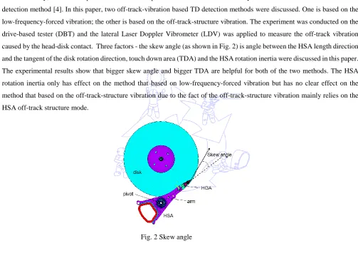
caused by the head-disk contact. Three factors - the skew angle (as shown in Fig. 2) is angle between the HSA length direction
and the tangent of the disk rotation direction, touch down area (TDA) and the HSA rotation inertia were discussed in this paper.
The experimental results show that bigger skew angle and bigger TDA are helpful for both of the two methods. The HSA
rotation inertia only has effect on the method that based on low-frequency-forced vibration but has no clear effect on the
method that based on the off-track-structure vibration due to the fact of the off-track-structure vibration mainly relies on the
HSA off-track structure mode.
Fig. 2 Skew angle
2.
Experimental Setup
In this paper, the experiment was conducted on a 2.5 inch DBT tester (as shown in Fig. 3). A spinbox was used to drive
the spindle with 5400 RPM rotating speed. To investigate the head-disk touch down detectability based on the off-track
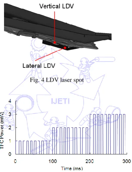
vibration, two LDVs were utilized to measure the vertical vibration and off-track vibration synchronously. The lateral LDV
focused on the side of the slider near the read/write element. The vertical LDV focused on the leg of head-gimbal assembly
(HGA) (as shown in Fig. 4). The vertical LDV TDP will be detected when the vertical LDV response reached a threshold of
6*sigma of the baseline. This vertical LDV TDP was used as a reference of the head-disk first TD, indicating the beginning of
head-disk contact together [5-6]. A TFC control module was used to supply the TFC power to the heating element of the slider.
For the low frequency forced vibration detectability study, a 100Hz square wave TFC power (as shown in Fig. 5) was applied
to the heating element. For the off-track-structure vibration detectability study, a step-like TFC power was applied to heating
Fig. 3 Experimental setup
Fig. 4 LDV laser spot
Fig. 5 100Hz square wave TFC power
Fig. 6 Step-like TFC power Drive VCM
Drive Spindle
3.
Experiment Result and Discussion
3.1. Skew angle effect
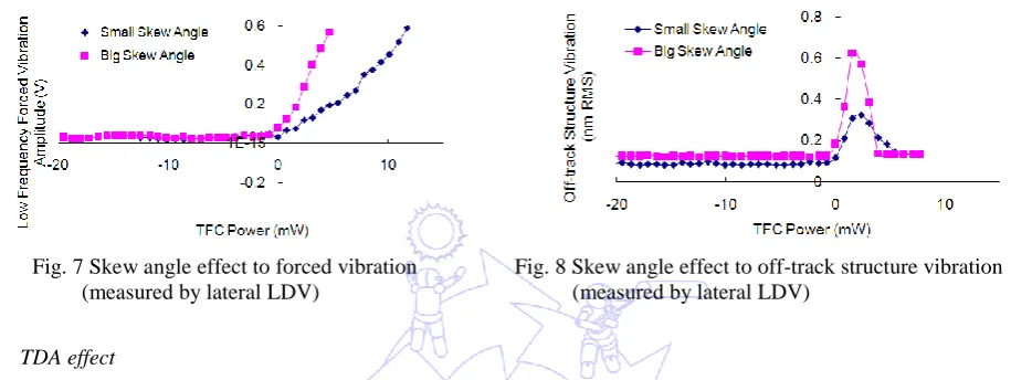
Fig. 7 and Fig. 8 are the results of low-frequency-forced vibration and off-track-structure vibration in different skew
angle. The TFC power was offset according to the vertical LDV TDP. The 0 mW in the following figures (Figs. 7-8, Figs.
11-14) is the power of vertical LDV TDP, indicating the beginning of the head-disk contact. Both the low-frequency-forced
vibration and off-track-structure vibration are more sensitive to the head-disk contact in bigger skew angle. This can be
explained by the bigger off-track component force, as illustrated by Eq. (3).
Off-track component force = Friction force * Sin (skew angle) (3)
Fig. 7 Skew angle effect to forced vibration (measured by lateral LDV)
Fig. 8 Skew angle effect to off-track structure vibration (measured by lateral LDV)
3.2. TDA effect
To study the TDA effect, there are two the same with HSAs but with different TFC protrusion profiles, were used for
comparative study. To verify the TDA difference of these two TFC protrusion profiles, these two HSAs were selected with the
same TFCprotrusion efficiency. And the vertical LDV was used to detect the LDV TDP (indicate the beginning of head-disk
contact) of these two HSAs were overdriven 5 mW (applying a TFC power of LDV TDP + 5mW to ensure the head contact
with disk) for about 5minutes. After the overdrive experiment, the contact area between the head and disk will be worn out. The
worn out area can be checked with the Scanning Electric Microscope (SEM) because it will be lower than the other area. The
following Fig. 9 and Fig. 10 are the SEM results for these two TFC protrusion profile designs after overdrive experiment. The
light area is lower than the dark area in the SEM image so the light area is the touch down area (TDA) that was worn out.
Comparing with the SEM image of Fig. 9 and Fig. 10, it is very clear that Fig. 9 design has a much bigger TDA than the Fig. 10
design.
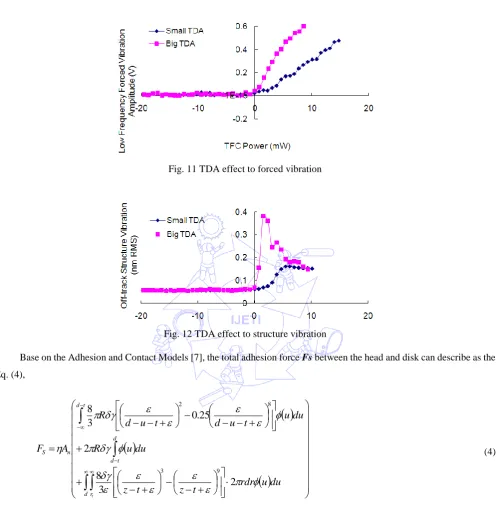
Fig. 11 TDA effect to forced vibration
Fig. 12 TDA effect to structure vibration
Base on the Adhesion and Contact Models [7], the total adhesion force Fs between the head and disk can describe as the
Eq. (4),
d r d t d t d n S tdu
u
rdr
t
z
t
z
du
u
R
du
u
t
u
d
t
u
d
R
A
F
2
3
8
2
25
.
0
3
8
9 3 8 2 (4)where
η
is the areal density of asperities,An
is the nominal contact area,R
is the radius of curvature of asperity summits,
is the adhesion energy per unit area for the head–disk interface,
is the equilibrium intermolecular spacing, d is theseparation of the mean plane of asperity heights, u is the asperity height,
t
is the thickness of the lubricant layer,
(
u
)
is theprobability density function of asperity heights [7].
Base on the Eq. (4), the contact force has a linear relationship to the TDA. The design with bigger TDA will have a
3.3. HSA rotation inertia effect
Fig. 13 Rotation inertia effect to forced vibration
To study the rotation inertia effect on the off-track-vibration touch-down detectability, two HSAs with different rotation
inertia were used for comparative experimental study. These two HSAs were sharing the same HGA design and with different
arms. One HSA is for one-disk HDD with two arms, the other HSA is for 3-disks HDD with 4 arms. The 4-arm HSA has much
bigger rotation inertia than 2-arm HSA. Fig. 13 is the result of low-frequency-forced vibration for these two HSAs. The HSA
with smaller rotation inertia has sharper lateral response after TD and better TD detectability than the HSA with bigger rotation
inertia. Fig. 14 is off-track-structure vibration for these two HSAs with different rotation inertia. The off-track-structure
vibration for these two HSAs is very close.
Fig. 14 Rotation inertia effect to structure vibration
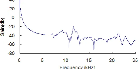
Fig. 15 is the HSA lateral frequency-response function (FRF) which is very clean and has no any structure mode before
3 kHz. Therefore, for the 100Hz forced vibration, the HSA can be treated as rigid body and rotate along the center of the pivot
and the amplitude of the 100Hz forced vibration does not rely on the HSA structure mode.
Fig. 16 Forced vibration FFT Fig. 17 Forced vibration FFT (zoomed to 500Hz)
According to the Eq. (5), with the same excitation force and torque M, the smaller the rotation inertia I, the bigger the
angular acceleration β and off-track-vibration amplitude is. Therefore, the rotation inertia has a significant effect on the
response of low-frequency-forced vibration. With the same contact force, the smaller rotational inertia, the sharper of the
low-frequency-forced vibration, the better sensitivity for TD detection is.
I
M (5)
But for the off-track-structure vibration excited by the head-disk contact, the lateral response mainly relies on the HSA
off-track structure mode [8] rather than the rotation of the HSA. So the HSA rotation inertia has very limited effect on the
off-track-structure vibration.
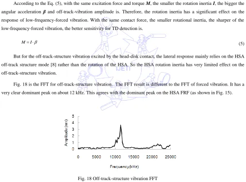
Fig. 18 is the FFT for off-track-structure vibration. The FFT result is different to the FFT of forced vibration. It has a
very clear dominant peak on about 12 kHz. This agrees with the dominant peak on the HSA FRF (as shown in Fig. 15).
Fig. 18 Off-track-structure vibration FFT
4.
Conclusion
In this paper, a systematic study performed on how to improve the off-track-vibration-based TD detection sensitivity and
two popular off-track-vibration-based TD detection methods were discussed. Also, the effects of skew angle, TDA and rotation
inertia to these two methods were studied. Base on the experimental result, both of the low-frequency-forced-vibration-based
method and off-track-structure-vibration-based method are very sensitive to the skew angle and TDA. Bigger skew angle and 0
1 2
0 5000 10000 15000 20000 25000
Frequency (Hz)
Am
p
lit
u
d
TDA is helpful for good TD detection sensitivity. The rotation inertia has a significant effect on the
low-frequency-forced-vibration-based method only. For such a method, smaller rotation inertia has better TD sensitivity.
These findings were very helpful for the HDD design optimization to achieve good off-track-vibration-based TD detection.
Table 1 summarizes the TD detectability optimization for these two methods.
Table 1 TD detectability optimization summary
Skew angle TDA Rotation inertia
Low frequency
forced vibration Bigger skew angle Bigger TDA Smaller rotation inertia Off-track structure
vibration Bigger skew angle Bigger TDA No clear effect
References
[1] J. Juang, T. Nakamura, B. Knigge, Y. Luo, W. Hsiao, K. Kuroki, F. Huang, and P. Baumgart, “Numerical and experimental analyses of nanometer-scale flying height control of magnetic head with heating element,” IEEE Transactions on Magnetics, vol. 44, No. 11, pp. 3679–3682, Nov. 2008.
[2] Y. Wang, X. H. Jin, S. X. Chen, X. F. Wei, and K. L. Tsu, “Effect of low-frequency vibration in z-direction (out-of-plane) on slider dynamics,” IEEE Transactions on Magnetics, to appear.
[3] N. Li, L. Zheng, Y. Meng, and D. B. Bogy, “Experimental study of head-disk interface flyability and durability at sub-1-nm clearance,” IEEE Transactions on Magnetics, vol. 45, No. 10, pp. 3624–3627, Oct. 2009.
[4] A. Khurshudov, P. Ivett, “Head–Disk contact detection in the hard-disk drives,” Wear 255, pp. 1314–1322, 2003. [5] Q. H. Zeng, C. H. Yang, S. Ka, and E. Cha, “An experimental and simulation study of touchdown dynamics,” IEEE
Transactions on Magnetics, vol. 47, No. 10, pp. 3433–3436, Oct. 2011.
[6] R. Pit, Q. H. Zeng, Q. Dai, and B. Marchon, “Experimental study of lubricant–slider interactions,” IEEE Transactions on Magnetics, vol. 39, No. 2, pp. 740–742, Mar. 2003.
[7] J. Zheng, D. B. Bogy, “Investigation of flying-height stability of thermal fly-height control sliders in lubricant or solid contact with roughness,” Tribol Lett, vol. 38, pp.283–289, 2010.