Abstract— A fundamental requirement for executing Discrete Event Simulation (DES) is incorporating a data structure that represents process, product and resource information, and their interrelations. Further, the capability of integrating this data structure with other types of information such as geometry (e.g. for sizes of products or distances of transports) is of vital interest. Manufacturing information is normally not integrated but is heterogeneous and stored in different Computer Aided Design (CAD) and Computer Aided Manufacturing (CAM) applications in the factory plant. Therefore this paper aims to describe how to represent the main required operational data of a manufacturing system for DES by using ISO 10303 Application Protocol 214 (STEP AP214) in order to fulfill the mentioned characteristics of data and information. Stochastic properties of manufacturing resources and corresponding processes such as measured cycle time and disturbances information are represented using application module 1274 (ISO 10303- 1274) that defines a particular schema for probability distribution representation. A test implementation of the mentioned data including a graphical user interface has been carried out to show the feasibility of the research approach.
Index Terms— Computer aided engineering, Computer integrated manufacturing, Information representation, Computer applications
I. INTRODUCTION
IGITAL manufacturing is defined as a technology to process information to verify and optimize the manufacturing of products [1]. Discrete Event Simulation has shown a rigorous capability as a tool in the digital manufacturing context for the purpose of material flow analysis. However DES is rarely used in industry due to the ineffective and inefficient data management that is required for the DES implementation [2]. Extensive and
This work is funded by VINNOVA (The Swedish Governmental Agency for Innovation Systems) and has been supported by XPRES (Initiative for excellence in production research). We also thank Scania CV AB for fruitful discussions and support.
N. Shariatzadeh is with the Royal Institute of Technology, Department of Industrial Production, Stockholm, Sweden, phone: +46-8-790-8338; e-mail: navidsz@ KTH.se.
G. Sivard, is with the Royal Institute of Technology, Department of Industrial Production, Stockholm, Sweden, phone:+ 46-8- 790-9080; e-mail: [email protected].
M. Hedlind. is with Scania CV AB, Department of Industrial Development, Stockholm, Sweden, phone:+46-8-55386000 ,e-mail: [email protected]
consuming data preparation is one of the main reasons of this problem.
In addition, the required data for DES are heterogeneous and reside in different computer applications and databases. For instance, failure and disturbance data is stored in the databases of maintenance systems. Cycle times are defined by process planners and can be found in process planning applications, while geometrical data comes from CAD systems. Therefore, the representation of this data and information in an application and in a system-neutral format allows for easier data integration, for acceleration in the data preparation, and expedites updating DES models. This in turn prevents probable mistakes in data interpretation and facilitates data exchange among different computer applications.
There are a number of approaches that are able to develop data management architectures for capturing, structuring, storing and exchanging process specifications. Falkman [7] shows how process specifications represented as Petri Networks can be mapped to ISO 10303-214. This work represents process planning and conditions for process operation occurrences. However,the work does not focus on interrelated properties of processes, resources and products such as cycle times. Furthermore it does not specify the uncertainties embedded in the process such as the failure data Mean Time between Failure (MTBF) and Mean Time To Repair (MTTR).
Other research have been conducted on information modeling required for manufacturing processes, DES, online simulation, NC data and interlocking [8,9,10,11], However, little has been investigated concerning the connection between information and DES modelsm and integrating this information with other type of data.
There exist rich ontologies to represent manufacturing processes such as the Process Specification Language (PSL) [12], A Language for Process Specification (ALPS) [13], Core Plan Representation (CPR) [14], the <I-N-OVA> constraint model [15], the Visual Process Modeling Language (VPML) [16] and Petri Nets [17]. However since the aim of all ontologies is to represent knowledge of some domain (in this case manufacturing processes), integrating a specific ontology with other types of information is a laborious task. Moreover these approaches do not focus on shop floor data such as failure data. Boulonne indicates how operational data such as measured cycle time, MTBF, MTTR and energy consumption can be generated by using generic data extracted from
Material Flow Data Representation and
Integration Based on STEP
N. Shariatzadeh, G. Sivard and M. Hedlind
Royal Institute of Technology, Department of Industrial Production, Stockholm, Sweden
manufacturing databases [18]. They represent these operational data using the Core Manufacturing Simulation Data (CMSD) standard considering the stochastic processes properties. Riddick discusses representing geometrical or spatial aspects of manufacturing entities. However the CMSD standard does not rigorously cover all geometrical data and only focuses on simulation aspects such as boundary, placement and some other spatially-related aspects of the manufacturing entities [19]. Representations of this information using CMSD results in redundant data instantiation/conversion and waste of time since geometrical and spatial data already exist in CAD models and many Commercial CAD systems are able to translate them to the STandard for the Exchange of Product (STEP) model data that allows for interoperability.In the next section we discuss the necessity of integrating manufacturing processes with other types of information to support DES.
II. REQUIRED INFORMATION FOR MATERIAL FLOW AND PROCESS CONTROL
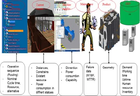
Required information for material flow representation and process control can be categorized as follows:
Product: Product breakdown structure and its geometry data are used for DES. For instance, the diameter of a cylinder is necessary to be able to identify the required capacity of a conveyor which is used in a DES model.
Layout: layout information such as general definitions of the boundary, placement and spatial relations of the manufacturing entities.
Manufacturing resources: their operational property such as the speed of a conveyor or energy consumption of a resource in different states.
Maintenance: manufacturing resources availability information such as uptimes and downtimes.
Process-plan: description of manufacturing processes sequence and product routing.
Enterprise resource planning: information about orders, production scheduling and production strategy.
Fig. 1. Required information for DES modeling
Figure 1 illustrates the various domains and their corresponding information to build up a DES model.
III. PROBLEM STATEMENT
Data and information regarding products, processes and manufacturing systems are stored in different systems and databases throughout the factory, such as the Manufacturing Execution System (MES), the Enterprise resource Planning ( ERP) and the PDM. This information is heterogeneous due to the lack of interoperability between the CAx commercial software and simulation software. Therefore capturing, structuring and representing this information requires harmonization of this heterogeneous information, and thus also providing the interoperability capability of these data.
This paper presents research on an information modeling schema for an integrated modeling of product, process and manufacturing system for the purpose of discrete event simulation. The schema is based on ISO 10303-214 International standard, namely the application protocol 214 (AP214). This schema has been implemented in a software platform that generates process specification using process schema represented in the CMSD standard, in layout systems, and product design. The presented schema and associated software can support DES, reconfiguration and optimization process in the shop floor.
IV. RESEARCH APPROACH
In this research ISO 10303 is utilized for the purpose of an integrated representation of product, process and manufacturing system. This standard has been chosen for this purpose in reference to the following essential characteristics:
1) Extensibility: the schema must be developed in a way that it can accommodate extensions of data in the overall data structure. This property is essential since during the life cycle of a manufacturing system and its reconfiguration new pieces of information might be needed. For instance, the distances that human operators walk can be important for the purpose of line balancing in manufacturing systems.
2) Interoperability: the data storage must be done in an application and system neutral format. Hence different software tools can use this information and perform analysis. Furthermore, data interoperability makes the communication of layout tools and simulation tools possible since important information of a DES comes from layout system such as distances among machines, stop times and so on.
3) Multi granularity: The schema must be designed to support different levels of analysis of data according to the required detail of information.
4) Generic: The schema must be generic to make it possible to be used for wide variety of manufacturing system.
planning, and product routing. Hence different users can exploit their required data in their desired level of detail.
Entities represented in the suggested schema of this research deal with the product, process, and resources to model a manufacturing system and the interrelation of entities are highlighted in order to represent the product, process and resources as whole.
This research has focused on four (4) tasks and development of the software application:
1) Development of an integrated product, process and resources schema based on ISO 10303-214.
2) Mapping the process schema described in CMSD standard to STEP standard.
3) Develop computer application to translate data represented in CMSD (XML) to STEP 214 and validate it.
4) Develop a computer application for process specification translation from CMSD (XML) and integration with geometry of products and resources exporting form commercial CAD system in STEP format.
V. STANDARD FOR INFORMATION EXCHANGE
ISO 10303 STEP is an international standard that “provides a representation of product information along with the necessary mechanisms and definitions to enable product data to be exchanged” [3]. The term exchange should be interpreted as the exchange of data between computer systems in environments associated with the complete life-cycle of a product, including manufacturing. As an introduction to the STEP standard the following concepts will be explained:
• Application protocol (AP);
• Application reference model (ARM); • Application interpreted model (AIM); • Integrated resource (IR);
• The exchange/sharing mechanisms.
Application protocols (AP): define the scope, context, and information requirements for a particular application, e.g., the automotive industry (AP214), or the electrical design and installation (AP212). An application protocol is divided into two different representations of the information requirements: the application reference model (ARM) and the application interpreted model (AIM). In depth information on application protocols and STEP, in general, are available in [4]–[5].
ARM and AIM: The ARM is used to capture the information requirements using application-based terminology, whereas the AIM is used to represent the information requirements in application- neutral terminology. Thus, the ARM provides a model that is easy to interpret and understand for domain experts. In addition, the AIM provides a mechanism for interoperability between different application protocols. In this paper, the AIM model of AP214 is used.
AP214 is an application protocol developed to consider the requirements of automotive industry on information exchange. However, Scheller has shown that the generic structure of AP214 can be used to represent any type of mechanical product, including a manufacturing resource [6].
Implementation of the standard is supported by ISO 10303_22 SDAI (standard data Access Interface). SDAI is an
abstract programming interface to access data models based on EXPRESS (ISO 10303-11). Express is a language that describes Information models in STEP. ISO 10303-27 specifies a Java binding to SDAI and is implemented in JSDAI, an open source development package produced by LKSoftWare GmbH.
VI. INTEGRATED SCHEMA FOR PRODUCT,PROCESS AND
RESOURCE
A. Product, Resource Information Model
Figure 2 illustrates the product schema in a generic way in the AIM level of the ISO 10303_214 Standard. The product schema is generic; therefore it can represent both product and resource. The entities “Product”, “Product_ definition_ formation” and “product_ definition” are used to represent a product in general regardless the aspects that must be represented such as geometry, structure, feature etc. However; for the purpose of representing a resource one need to use the entity“Product_definition_resource”.
The”Product_definition_resource” entity can be of type “Product_definition” and/or “Action resource”, and it specifies a machine or an instrument that is used to perform a process.
Fig. 2. Product schema to represent product and manufacturing resource in ISO 10303_214
A process is represented by the “Process_operation” entity. “Product_definition_formation” entity is a collector of definitions of a product. An “Application interpreted model” could use this entity to support the identification of different versions of a single product.
the product. If the “Product” entity is a product that is to be manufactured, the Name attribute of the
“product_related_product_category” must be instantiated as “part” and if it is a resource it must be instantiated as a “tool”.
Moreover; in AP214 each “product definition” entity and other related entities such as “product_definition_resource” must be connected with the entity “product_definition_ context” and “Applied_organization_assignment”.
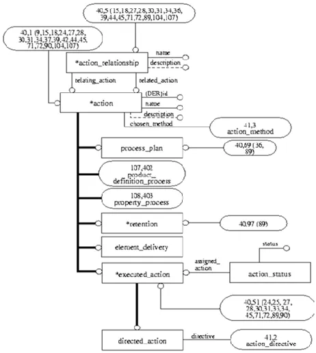
Fig. 3. Action schema to represent processes of a manufacturing system
B. Process Schema
Figure 3 demonstrates the process schema in the AIM level of the ISO 10303_214 Standard. A “Process_plan” is a type of action that specifies the information necessary for manufacturing planning. The relation_type specifies the meaning of the relationship. In the ARM level the following relation_type have been defined:
(1) “Alternative”: The application object defines a relationship where the related Activity may be used
alternatively instead of the relating Activity; (2) “Decomposition”: The application object defines a
relationship where the related Activity is one of potentially more sub-activities into which the relating
Activity is broken down. (3) “Derivation”: The application object defines a
relationship where the related Activity is derived from the relating activity. (4) “Exclusiveness”: The application object defines a
relationship where the relating and the related Activity
shall not have any overlap in time of execution. (5) “Precedence”: The application object defines a
relationship where the related Activity has higher priority than the relating Activity. (6) “Sequence”: The application object defines a relationship
where the relating Activity shall be completed before the related Activity starts.
(7) “Simultaneity”: The application object defines a relationship that establishes that both the relating and related Activity are considered as occurring during the same time period or shall be performed together in order to ensure consistency and enhance efficiency.
Fig. 4. Integrated schema of product, process, resource that represents the manufacturing system
C. Integrated Schema of Product, Process, Resource
In order to represent the manufacturing system the product, process and resource information and their interrelationship must be represented as a whole schema. Figure 4 shows an integrated schema for a product and a resource that performs a process on the product.
To represent the manufacturing processes that are performed with a resource, the “Poduct_definition_resource” entity is related by the entity” Action” and this action is already connected to the product schema as explained before. Hence, the relationship among product, process and resources can be established and represented. The product information includes ID, Name, Description, Life Cycle stage. The resource information includes ID, Name, Description, Category, and Operation.
Fig. 5. Representing MTBF and measured cycle time as properties of an “Action” that is performed by a resource on a product
D. Schema to Represent Failure Data and Measured Cycle Time
The most widely used failure information in discrete event simulation is MTBF and MTTR. MTBF is often in practice seen as a kind of total performance measure of a resource which performs many different operations on various products. Thus it might be difficult in practice to relate the MTBF to a specific combination of operation-product. Still, theoretically the MTBF is a kind of time which characterizes how the resource performs. Thus the time between failures is a property of an activity which in turn is related to both resource and the product that is being processed.
MTBF and MTTR can be represented by “Product-property” schema (ISO 10303-41) and “Process-“Product-property” (10303-49) schemas.
Figure 5 demonstrates an example of representing a property of a resource-process. The “Action entity “is connected to a “Process_operation” entity that is a manufacturing process. The “Action” is connected to the “Action_property” entity property that can be MTBF. “Action_property” entity is connected to the “Action_property_representation “entity that is used to represent the desired property. Measured cycle time is a cycle time that has been measured in the shop floor for example by executing stop-watch method. This property can be represented with the same schema. Moreover the cycle time that is identified through the process planning activity can also
be represented in the same way. However if measured cycle time is stochastic, its corresponding distribution is represented using AM 1274 that is explained in next section. Figure 5 shows the schema for representation of MTBF as a property of an action that is performed by a certain resource and produces a particular product.
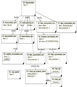
Fig. 6. Schema for probability distribution using AM 1274 ISO 10303
E. Schema of Probability Distribution
Figure 6 illustrates a MTBF representation that follows Normal distribution with mean that follows Normal distribution with mean 125 and Standard deviation 5.
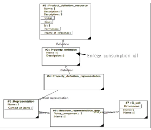
Fig. 7. Schema for representation energy consumption of resource
F. Representation of Energy consumption of manufacturing resources
Energy consumption analysis has been the subject of interest for DES to increase the ecological sustainability in production systems. Skoogh shows that the variability of energy consumptions in different statues of the machine (Idle, busy, standby) are low [20]. Therefore this research represents the energy consumption data in a deterministic way by using “Product_property-definition” schema (10303-41), representation schema” (10303-43) and “Measure schema” ISO 10303-41.
Figure 7 illustrates an example of energy consumption as a property of a resource.
G. Map CMSD TO STEP
GDM (Generic Data Management) tool is a software application developed by Chalmers University which extracts the generic data regarding cycle time and failures form the available databases in the plant, draw the histogram, execute the probability distribution fitting, and publish the result in XML format based on CMSD standard [21]. The CMSD Information Model defines a data specification for exchange of manufacturing data in a manufacturing simulation environment. The specification provides a neutral data format for integrating manufacturing applications and simulation. However it does not cover specification of implementation methods and execution behavior of the manufacturing system.
In GDM the toll raw data, describing all necessary behavior on the shop floor, are manually extracted from off-line copies
of two production databases, mainly using copy and paste functions. Moreover, filtering of irrelevant or incorrectly measured data was manually performed in MS Excel by simply identifying and deleting data points using process knowledge.
The computer application developed in this research extracts operational data from the output of GDM tool. Therefore a comparative study has been carried out to map the CMSD to STEP. The scope of data is limited to operation sequence, cycle time, failure data and energy consumption of resources in this research.
Table 1 shows some examples regarding the mapping table. The entities used in CMSD to represent a manufacturing system and properties for a DES model are described in [2].
Table 1. Example of mapping CMSD to STEP AP214
The main attributes of product, resource and processes that are considered in this schema are as follows:
● Product representation: unique ID, Name, Description, Life Cycle stage, Product process plan (a relation between product and processes).
● Resource representation: unique ID, Name, Description, Category, Operation.
● Representation of Stochastic operational characteristics of resources including Mean Time Between failure (MTBF) and Mean Time To Repair (MTTR).
● Processes required for product manufacturing:
○ Stochastic representation of Measured Cycle time;
○ Product routing (describes the material flow: operation sequence, operation alternatives and synchronization of operations - whether parallel or in sequence).
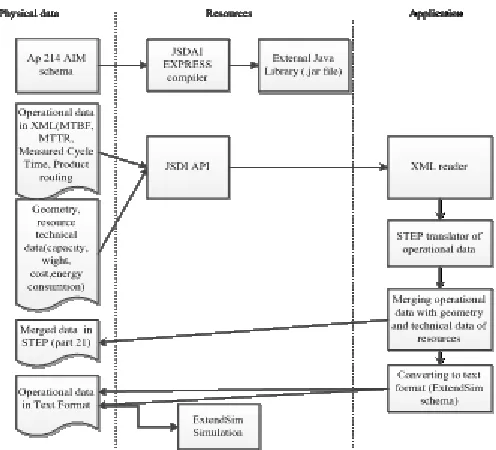
Fig. 8. System architecture of developed computer application for material flow data generator in STEP and integrator with other information
VII. SYSTEM ARCHITECTURE OF THE DEVELOPED COMPUTER
APPLICATION
This research includes development of one application for providing information for a Discrete Event Simulation Software tool. Figure 8 illustrates the system architecture of the developed computer application. This application is a STEP implementation based on the AP214 AIM schema. It was developed using the Java language because the STEP standard has a strong programming interfaces for Java. All data are represented with STEP part 21 that is the physical part of the standard. Other required data such as organizational data, technical information of a manufacturing resource (machine data card) can be extracted for other available databases or instantiated manually. The geometry data of a product or a resource are translated from any CAD system that is able to represent geometrical data rigorously in STEP format. After translation of operational data, these data are merged with geometry using the developed computer application. Now this repository of data and information can be used for extracting the desired information for the purposes of discrete event simulation. However, since one of the objectives of this test implementation is to export data to the ExtendSim software, the application extracts and converts the information to a text file that is recognizable for the
ExtendSim software. This will be discussed below. In the design stage, the integration of three layers is considered: physical data, resources, and application. The resources are collected in a layer to link the application with physical data. Physical data is the data physically stored in the hard disk. The application layer contains the developed programs.
VIII. CASE STUDY
This case study considers a manufacturing encompassing five manufacturing resources, one product and 5 processes. The purpose of the simulation is the calculation of throughput and energy consumption. Each resource includes energy data in three different states: busy, idle and standby. Each process-resource has MTBF, MTTR, measured cycle time, and nominal cycle time. The MTBF, MTTR and measured Cycle time are imported to the application in CMSD format (XML) and other information is extracted from other databases or set up manually. A graphical user interface was developed for end users. With this interface end users only need to identify the path of the CMSD file, the desired location for the STEP file and the database of the ExtendSim software. Finally by clicking the convert buttons the files will be converted in less that one minute.
Figure 9 demonstrates the flow of data translation and integration using the developed computer application. First manufacturing process specification in XML format is translated to STEP. In this step other organizational information is added as well. In second step this information is integrated with geometrical information. The geometrical data come from CAD systems. Finally three pieces of information including cycle time, MTBF and MTTR are exported to a readable text format for ExtendSIM simulation software.
Figure 10 illustrates the graphical interface and the various file formats during the conversion process. As mentioned before some geometrical data of a resource and product are used for DES as well. For instance, the capacity of a straight roller conveyor is the result of the length of the conveyor divided by the diameter of a semi finished product. Therefore the developed computer application merges the operational data with geometrical data of resources or products.
The geometry of a resource or a product is imported from commercial CAD systems. When merging geometry and process schemas, the header, data section and entities “product“ and Product_definition_formation” are duplicated. As such the application eliminates the extra entities, and combines geometrical data and process data, etc.
The” Product_definition-formation” is the entity that collects all product representation aspects and exists in geometry, technical data, and property schema. Therefore the computer application searches products with the same ID, keeps one “Product_definition_representsation”, elimates the rest and conducts the necessary relationships among the remaining “product_definition_representation” entity and the other entities that were connected with
IX. CONCLUSION
This research focuses on representing material flow data and information in a system neutral format by utilizing the STEP standard. Moreover, it shows the feasibility of integrating this data with other kinds of information such as geometry and technical data such as machine data card. This makes the exchange of data among different CAx and simulation applications less erroneous and more efficient. Moreover storing operational data in a system neutral repository decouples the information and the simulation model thus making one model reusable for other similar cases or making it easier to redo the simulation whenever information is updated. Further, to exemplify and verify the approach a computer application was developed to convert operational data from CMSD (XML) to STEP, integrating it with geometrical information from CAD systems and finally converting the data to a readable format for ExtendSIM simulation software.
REFERENCES
[1] T. Kjellberg, Z. Katz, M. Larsson, “The Digital Factory Supporting Changeability of Manufacturing Systems,” CIRP ISMS, 2005, pp. [2] A.-Boulonne, B. Johansson, A. Skoogh, “Simulation Data Architecture
for Sustainable Development,” Proceedings of the 2010 Winter Simulation Conference, 42 s, 2010, 3435-3446.
[3] ISO 10303:214 Industrial Automation Systems and Integration— Product Data representation- and exchange— Introduction, I. TS 184/SC4184, 2009
[4] ISO 10303:214 Industrial Automation Systems and Integration— Product Data representation- and exchange— ARM index, I. TS 184/SC4184, 2009.
[5] ISO 10303:214 Industrial Automation Systems and Integration— Product Data representation- and exchange— AIM index, I. TS 184/SC4184, 2009
[6] A. Scheller, “Information modeling for distributed applications,” in Proc. 2nd IEEE Workshop on Future Trends Distrib. Comput. Syst., 1990.
[7] P. Falkman, J. Nielsen, B. Lennartson, A. E. Cheplin, “ Generation of STEP 214 Models From Discrete Event Systems for Process Planning and Control,” IEEE Trans. Automation Science and Engineering, vol. 5(1), , pp. 113-126, 2008.
[8] M. Johansson, “Information modeling for manufacturing system,”
Ph.D. dissertation, Dept. Industrial. Eng., Royal Institute of
Technology, 2004.
[9] H.-P. Wiendahl, H. Scheffczyk, “Simulation Based Analysis of Complex Production Systems with Methods of Nonlinear Dynamics”, CIRP Annals - Manufacturing Technology,, Vol.48(1), pp.357-360, 1999.
[10] W. Eversheim, G. Marczinski, and R. Cremer, “Structured modeling of manufacturing processes as NC-data preparation,” Ann. CIRP, vol.40/1, 1991.
[11] H.-P. Wiendahl, V. Ahrens, “Agent-Based Control of Self-Organized Production Systems”, CIRP Annals - Manufacturing Technology, , Volume 46, Issue 1, Pages 365–368, 1997.
[12] M. Gruninger, “Ontology of the Process Specification Language”, Institute for Systems Research, University of Maryland, College Park, 2001.
[13] Catron BA, Ray SR , ALPS: a language for process specification , “Computer Integrated Manufacturing 4(2):105–113, (1991).
[14] Pease R, Carrico T) The JTF ATD core plan representation: a progress report. Proceedings of the AAAI Spring Symposium on Ontological Engineering. AAAI Press, Stanford, 1997.
[15] Tate A ,”Representing plans as a set of constraints—the <IN- OVA> model“ , Proceedings of the Third International Conference on Artificial Intelligence Planning Systems(AIPS-96), Edinburgh, 1996. [16] http://www.issi.com/proslcse-3.5i/vpml.html.
[17] Peterson J,” Petri net theory and modeling systems”. Prentice Hall, New Jersey, 1981.
[18] A. Skoogh, “Automation of Data Input Management-Increasing Efficiency in Simulation of Production Flow ,” Ph.D. dissertation, Dept. Product and Production. Development., Chalmers Univ, 2011. [19] F. Riddick, “Representing layout information in the CMSD
specification”, Simulation Conference, WSC , 1777 – 1784, 2008. [20] A. Skoogh, B Johansson, L. Hanson, “Data Requirements and
Representation for Simulation of Energy Consumption in Product Systems”, In Proceedings of the 44th CIRP Conference on Manufacturing Systems, 2011
[21] A. Skoogh, B. Johansson and J. Stahre, “Automated input data management: evaluation of a concept for reduced time consumption in discrete event simulation”, The Society for Modeling and Simulation International, DOI: 10.1177/003754971244340 1_15, 2012
Navid Shariatzadeh has a M.Sc. in Mechanical Engineering. He is working towards a Ph.D. degree at the Department of Production Engineering, KTH (Royal Institute of Technology), Stockholm, Sweden, in the field of information modeling and management within the manufacturing area. His research has been conducted in collaboration with industrial partners such as Scania, AB Volvo and Volvo Car