ISSN: 1942-9703 / © 2016 IIJ Abstract—We propose a new control architecture to
perform Perfect Tracking for Multiple-Input Multiple-Output (MIMO) systems. Perfect Tracking is the task of very closely following a reference signal or trajectory by a system in the absence of modelling error or external noise. The architecture in this paper is based on the Dual Feedforward Method which has previously been applied for Single-Input Single-Output systems. Extension and generalization of the method to MIMO systems is non-trivial and our main contribution lies in designing the two feedforward paths through Right Matrix Fraction Description (RMFD) which enables perfect tracking of continuous-time MIMO systems. The paper presents the proposed architecture, the design methodology and illustrative simulation results. The architecture is also successfully implemented on the classic virtual Quadruple Tank laboratory apparatus.
Index Terms—Controller design, feedback, tracking control, modelling and simulation
I. INTRODUCTION
erfect Tracking is the task where a system seeks to track a given reference trajectory with almost instantaneous settling time and deviating from the trajectory only very minutely, if at all. Tracking is an important and integral part of space- vehicle systems, robotic systems, manufacturing systems, and industrial operations involving control of temperature, pressure, flow, etc. These are dynamic systems, which suggest that the tracking mechanism in these systems needs to be dynamic; it should be able to track multiple reference points, if required, and achieve Perfect Tracking. Previously Perfect Tracking has been achieved in robot motion planning [1][2] and also in non-minimum phase magnetic levitation systems [3]. Another approach for perfect tracking by implementing internal model principle (IMP) [4][5] called Hybrid Reference Control (HRC) was developed in [6], further developed with optimal control [17] and using ANFIS [8].
In [9], a new method of achieving Perfect Tracking for non-minimum phase systems was introduced - The Dual Feedforward Method. However, a major limitation of most of these methods is that they are designed for SISO (Single Input Single Output) systems only. Most practical systems of interest are MIMO (Multiple Input and Multiple Output) systems, starting from home appliances to airplanes. Hence we look into the problem of designing a perfect tracking method for MIMO systems.
Manuscript received August 5, 2015.
Syed Mahdi Azam is with Colorado State University, USA. (email: [email protected])
Lamia Iftekhar is with North South University, Dhaka, Bangladesh.(Phone:01686769679,email: [email protected])
.
In this paper, it is proposed an architecture which will perform Perfect Tracking of MIMO systems using the Dual Feedforward Method. In the proposed model, the MIMO systems are considered as linear, continuous-time and square systems. The advantage of this architecture is that the adaptation is not taking place inside the feedback loop, which means internal stability is guaranteed while the controllers adapt in real-time, provided the two feedforward controllers stay stable. But the existing SISO-focused architecture cannot be directly implemented to MIMO systems. A new design method for constructing feedforward paths are proposed in this paper that makes this architecture suitable for MIMO systems.
The dual feedfoward architecture can be implemented in a single controller. Alternatively, the dual feedforward can be separated in another different device with is linked to the feedback controller via transmission signal such as current or voltage signals. In modern control and automation technology, the transmission can be carried out using digital industrial communication such as RS 232, RS 485, ethernet or wireless communications, to illustrate [10][11][12][13]. The set-point implementation for perfect tracking with transient response improvement has been applied successfully on speed control of AC-motor by using ANFIS [8]. However, for implementation in a complex networked system, latency occurred in the communication network should be considered as it might induce big delay time [14]
The rest of the paper is organized as follows. Section II presents background materials, namely, MIMO system basics and the existing Dual Feedforward architecture for perfect tracking that works only on SISO systems. Section III presents our main contribution - the proposed architecture. Section IV discusses a couple of illustrative simulation results followed by presentation of the results of this method implemented on the classic problem of the Quadruple Tank laboratory apparatus. The paper concludes with a summary and an indication of some future directions.
II. BACKGROUND
Consider a linear MIMO system in state-space form as follows
x˙ (t) = Ax(t) + Bu(t) (1)
y(t) = Cx(t) + Du(t) (2)
Here x(t) represents the state vector, A is the system matrix, B is the input matrix, C is the output matrix and D represents the feedback matrix. Let,
Perfect Tracking of MIMO Systems using
Dual Feedforward Method
Syed M. Azam and Lamia Iftekhar
u(t) ∈ Rm y(t) ∈ Rm
be input and output vectors respectively. As there are m inputs and m outputs, this is a square MIMO system.
A. Transfer Function of MIMO Systems
Laplace Transformation of (1) and (2) leads to :
sX(s) − x(0) = AX(s) + BU (s) (3) Y (s) = CX(s) + DU (s) (4)
where, ℒ{u(t)} = U (s), ℒ {x(t)} = X(s) and
ℒ {y(t)} = Y (s). Assuming zero initial conditions, i.e, x (0) = 0, we obtain the following transfer function G(s)
G(s) = 𝑌𝑌(𝑠𝑠)
𝐺𝐺(𝑠𝑠) = C(sI − A)
-1B + D
(5)
Here, G(s) is of the following form:
𝐺𝐺(𝑠𝑠) = �
𝐺𝐺
11⋮
⋯ 𝐺𝐺
⋱
1𝑚𝑚⋮
𝐺𝐺
𝑚𝑚1⋯ 𝐺𝐺
𝑚𝑚𝑚𝑚�
where Gij(s) denotes the transfer function from the ith input to the jth output.
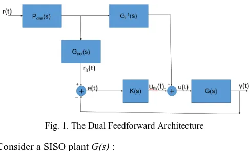
B. The Dual Feedforward Method for Perfect Tracking
For a SISO system, the Dual Feedforward architecture is given as follows (as proposed in [9]):
Fig. 1. The Dual Feedforward Architecture Consider a SISO plant G(s) :
G(s) = 𝐾𝐾𝐷𝐷𝐷𝐷𝑁𝑁𝑛𝑛𝑛𝑛𝑛𝑛(𝑠𝑠)𝑁𝑁𝑛𝑛𝑛𝑛(𝑠𝑠)𝑒𝑒
𝑠𝑠𝑠𝑠
𝐷𝐷𝑠𝑠(𝑠𝑠)𝐷𝐷𝑢𝑢(𝑠𝑠) (7) which is modeled by a proper Linear Time Invariant (LTI)system with non-minimum phase components such as time delays and right-half plane zeroes. G(s) can be split into two parts; a causal invertible part
Gi(s) = 𝐾𝐾𝐷𝐷𝐷𝐷𝑁𝑁𝑛𝑛𝑛𝑛(𝑠𝑠)
𝐷𝐷𝑠𝑠(𝑠𝑠)𝐷𝐷𝑢𝑢(𝑠𝑠) (8) and, a non-causal non-invertible part
Gnoi(s) = Nnmp(s)est (9)
So we have the following:
G(s) = Gi(s)Gnoi(s) (10) As equation (8) is invertible, therefore it can be said that:
G-1i(s) = 𝐷𝐷𝑠𝑠(𝑠𝑠)𝐷𝐷𝑢𝑢(𝑠𝑠)
𝐾𝐾𝐷𝐷𝐷𝐷𝑁𝑁𝑛𝑛𝑛𝑛(𝑠𝑠) (11) Observing the Dual Feedforward Architecture there are two feedforward paths FF1(s) and FF2(s), where,
FF1(s) = Pdes(s)Gnoi(s) (12) and,
FF2(s) = Pdes (s) G-1i (s) (13) In order to guarantee perfect tracking the following conditions must be satisfied:
• FF1(s) and FF2(s) must be stable proper transfer functions.
• The designing parameter Pdesand Gnoi should have the following property Pdes(0)Gnoi(0) = 1
Implementation of this perfect tracking method cannot easily be extended to MIMO systems because in a MIMO system there are can be multiple transfer functions defining the system. Therefore, we cannot split the system into two parts as easily we did for a SISO system. In the next section wepresent our new architecture for achieving perfect tracking of MIMO systems, where the MIMO system is decomposed using a different technique.
III. MIMO SYSTEM TRACKING USING DUAL-FEEDFORWARD METHOD
According to the Dual Feedforward architecture presented in Fig. 1, the system G(s) needs to be divided into two parts to make the feedforward paths. When handling a MIMO system such as in (6), it can be observed that there are more than one rational function to be split and hence we simply cannot execute the method which was applied for SISO. Nevertheless, if we wanted to execute similar method of splitting as used in a SISO system, we had to deal every transfer function in the MIMO system separately, which means the execution time for perfect tracking will be really long and not effective. To avoid these dilemmas, a different approach for splitting a MIMO system was used, which is called Matrix Fraction Description (MFD).
A. MFD (Matrix Fraction Description)
The Rational Matrix G(s) which was our transfer function, can be written as a fraction of two polynomial matrices. And, as the product of two matrices is not commutative, there are two different ways to proceed [15].
There exists a right matrix fraction description or RMFD which can be defined as:
G(s) = GN(s)GD-1(s)
ISSN: 1942-9703 / © 2016 IIJ G(s) = GD-1(s)GN(s)
Here, the non-singular matrix is entering G(s) from the left. G(s) can also be presented as:
G(s) =𝑁𝑁(𝑠𝑠)
𝐷𝐷(𝑠𝑠) (14)
where N(s) is the numerator matrix polynomial function and d(s) is the least common multiple of the denominators of the entries in G(s). Using N(s) and d(s), RMFD can be formed as:
G(s) = GN(s)GD-1(s) (15) where,
GD(s) = d(s)I (16) Here, I is the Identity Matrix, and
GN(s) = N(s) (17)
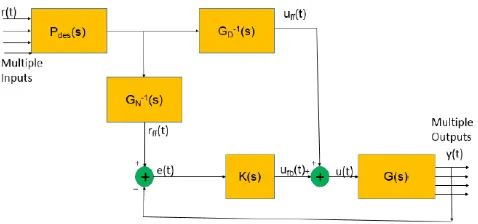
B. The Proposed Architecture
We propose the Dual Feedforward architecture for perfect tracking of MIMO systems as follows:
Fig. 2. The Dual Feedforward Architecture for MIMO systems Despite using the Dual Feedforward method, the feedforward paths cannot be constructed as the same way as it was for a
SISO system; this is because of GN(s).GN(s) is not a proper transfer function; therefore constructing an unstable system in a real life situation is not feasible. So, to have another
feedforward path we will use G-1N (s) to give us the second feedforward path.
We now present the steps to establish the Dual Feedforward Method for a MIMO system:
• The system is decomposed into its Right Matrix Fraction Description (RMFD), to establish the two feedforward paths. Performing RMFD will give us two functions Gn(s) and Gd(s).
• FF1(s) will be constructed as such that:
FF1(s) = Pdes(s)G-1N (s) (18) • Then FF2(s) would be constructed as such that: FF2(s) = Pdes(s)G
-1
D (s) (19)
While performing the Dual Feedforward Method for a MIMO system, it is assumed that the transfer function of the system can be split into RMFDs. considering they follow the coprime
factorization property presented in [3]. To construct Pdes(s) we use the equation of the first feedforward path FF1(s)
considering the initial condition s = 0. So, the equation for
finding Pdes(0) becomes:
Pdes(0) = IG-1N (0) (20) where,
I = �1 0
0 1�
The architecture presented here is based on feedforward paths but the feedback controller K(s) plays a significant role, as it helps reduce the steady state errors in the system. And, finally the transfer function of the system becomes:
𝑌𝑌
𝑅𝑅 = G(s)( G
-1
D (s) Pdes(s) + G-1N (s) Pdes(s)K(s)) / (1 + G(s)K(s)) (21)
IV. SIMULATIONS
In this section simulation of two systems are presented, where the Dual Feedforward method is applied to achieve perfect tracking. One is a 2-input, 2-output system, while the other is a 3 by 3 system.
A. Simulation-1
Consider a 2 by 2 system, whose transfer function is given as:
G(s) =
�
4 (𝑠𝑠+1)(𝑠𝑠+2)−0.5 (𝑠𝑠+1) 1
(𝑠𝑠+2)
2 (𝑠𝑠+1)(𝑠𝑠+2)
�
(22)Following (16) and (17) the RMFD of G(s) is:
GN(s) = � 4 −0.5(𝑠𝑠 + 2)
(𝑠𝑠 + 1) 2 � (23)
and,
GD(s) = �(𝑠𝑠 + 1)(𝑠𝑠 + 2) 0
0 (𝑠𝑠 + 1)(𝑠𝑠 + 2)� (24)
According to the (18) and (19), we need to find G-1D (s), and
G-1N (s) to create out feedforward paths FF1(s) and FF2(s). Using (23) and (24) we get,
G-1N (s) =
�
4 (𝑠𝑠2+3𝑠𝑠+18)𝑠𝑠+2 (𝑠𝑠2+3𝑠𝑠+18)
−2𝑠𝑠−2 (𝑠𝑠2+3𝑠𝑠+18)
8 (𝑠𝑠2+3𝑠𝑠+18)
�
(25)G-1D (s) =
�
1(𝑠𝑠+1)(𝑠𝑠+2)
0
0
(𝑠𝑠+1)(𝑠𝑠+2)1�
(26) After finding G-1N (s) and G-1D (s), Pdes(s) needs to bedesigned. To design Pdes(s) we have to keep in mind the condition of perfect tracking presented in (20).
With s = 0 in GN(s), we get
GN(0) = �4 −2
2 8 �
Altering the equation Pdes(0)G-1N (0) = I gives us Pdes(0) = IGN(0)
which means for this particular problem,
Pdes(0) = �4 −1
Thus, based on our Pdes(0) we can now design Pdes(s). For
this particular G(s), Pdes(s) has been designed as below:
Pdes =
�
4 (𝑠𝑠+1)2−1 (𝑠𝑠+1)2
1 (𝑠𝑠+1)2
2 (𝑠𝑠+1)2
�
(28)But before the execution of the Dual Feedforward Architecture on G(s) let’s have a look at how G(s) behaves when it was asked to track the value 1 at Output 1 and 2. From Fig.3 it can be seen that none of the outputs could track the desired value
of 1. Output 1 tracked a value of 4.5 and Output 2 tracked the value of 1.5. But observing the effect of Dual Feedforward architecture as shown in Fig.4, it can be seen that both the outputs have tracked the desired value of 2.
Fig. 3. Response of a 2-input, 2-output system without the Dual Feedforward
Fig. 4. Response of the above 2-input, 2-output system with the Dual Feedforward Method
A. Simulation-2
Consider a 3 by 3 system with the following transfer function:
G(s) =
⎢
⎢
⎡
(𝑠𝑠+1)(𝑠𝑠+2)45
(𝑠𝑠+1)
0
1 (𝑠𝑠+2)
2
(𝑠𝑠+1)(𝑠𝑠+2)
0
⎥
⎥
⎤
(29)
Following (16) and (17) the inverse of the RMFDs become,
G-1D (s) =
⎣
⎢
⎢
⎢
⎡
(𝑠𝑠2+3𝑠𝑠+2)10
0
0
(𝑠𝑠2+3𝑠𝑠+2)10
0
0
(𝑠𝑠2+3𝑠𝑠+2)1⎦
⎥
⎥
⎥
⎤
(30)
G-1N (s) =
⎣
⎢
⎢
⎢
⎡
(𝑠𝑠2+3𝑠𝑠+0.4)−0.40.2𝑠𝑠+0.2 (𝑠𝑠2+3𝑠𝑠+0.4)
0.2𝑠𝑠2+0.2𝑠𝑠
(𝑠𝑠2+3𝑠𝑠+0.4)
𝑠𝑠+2 (𝑠𝑠2+3𝑠𝑠+0.4)
−0.8 (𝑠𝑠2+3𝑠𝑠+0.4)
−1.2𝑠𝑠2−0.8𝑠𝑠
(𝑠𝑠2+3𝑠𝑠+0.4)
0
0
1𝑠𝑠⎦
⎥
⎥
⎥
⎤
(31)
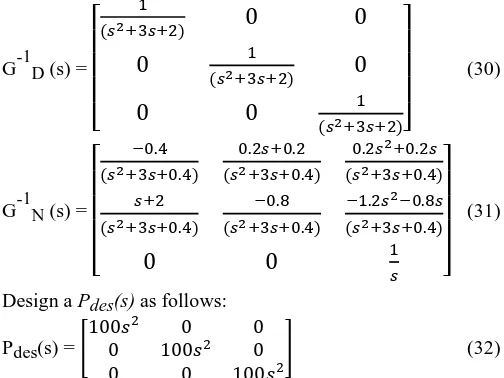
Design a Pdes(s) as follows:
Pdes(s) = �100𝑠𝑠
2 0 0
0 100𝑠𝑠2 0
0 0 100𝑠𝑠2�
(32)
When asked to track the value 2 at all outputs, the system behaves as in Fig.5 without the Dual Feedforward method. As
Fig. 5. Tracking attempted by a 3-input,3-output system without the Dual Feedforward method
it is observed here, all the outputs of the system fails to track their reference value 2. The outputs track values of 3, 6 and 9 respectively. From Fig.6 we can see that the reference value 2 has been perfectly tracked after the Dual Feedforward method has been applied.
ISSN: 1942-9703 / © 2016 IIJ V. AN APPLICATION: CONTROLLING WATER FLOW IN A
QUADRUPLE TANK
In this section we apply our technique on The Quadruple Tank which is a classic problem and evaluate our results. In [16] the transfer function of the Quadruple Tank was given as:
G(s) =
�
3.7𝑥𝑥1
62𝑠𝑠+1
3.7(1−𝑥𝑥2)
(23𝑠𝑠+1)(62𝑠𝑠+1) 4.7(1−𝑥𝑥1)
(30𝑠𝑠+1)(90𝑠𝑠+1)
4.7𝑥𝑥2
(90𝑠𝑠+1)
�
(33)where (x1 and x2) represent the proportion of the flow from the pump that goes into tanks. The system here has two multivariable zeroes which satisfy det (G(s)) = 0; (23s+1)(30s+1)- n = 0, where
n =(1−𝑥𝑥1)(1−𝑥𝑥2)
𝑥𝑥1𝑥𝑥2
Fig. 7. The Quadruple Tank system from [6]
To make the system minimum phase, the value of x1 + x2 should be greater than 1 but less than 2. Therefore, for our simulation we have taken x1 = 1 and x2 = 0.5, so G(s) becomes:
G(s) =
�
3.7𝑥𝑥162𝑠𝑠+1
1.85 (23𝑠𝑠+1)(62𝑠𝑠+1)
0
(90𝑠𝑠+1)2.35�
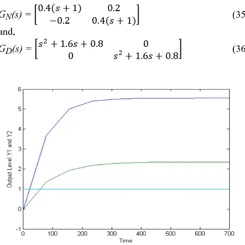
(34) When the desired output u1 = 1 and u2 = 1 is injected into the system, G(s) fails to track the inputs, resulting in the output y1 and y2 reaching a different level as shown in the Fig. 8 . Now, to apply the Dual Feedforward Method on this system, we need to find the RMFDs of the system and their inverses. These are found to be as follows:GN(s) = �0.4(𝑠𝑠 + 1) 0.2
−0.2 0.4(𝑠𝑠 + 1)� (35)
and,
GD(s) = �𝑠𝑠2+ 1.6𝑠𝑠 + 0.8 0
0 𝑠𝑠2+ 1.6𝑠𝑠 + 0.8� (36)
Fig. 8. Quadruple Tank’s Response before the Dual Feedforward Architecture
Using the (35) and (36),
G-1N(s) =
�
2.5 (𝑠𝑠+1) 𝑠𝑠2+2𝑠𝑠+1.25
−1.25 𝑠𝑠2+2𝑠𝑠+1.25
1.25 𝑠𝑠2+2𝑠𝑠+1.25
2.5 (𝑠𝑠+1) 𝑠𝑠2+2𝑠𝑠+1.25
�
(37)G-1D (s) =
�
1𝑠𝑠2+1.6𝑠𝑠+0.8
0
0
𝑠𝑠2+1.6𝑠𝑠+0.81�
(38)Fulfilling the condition Pdes(0)G-1N (0) = I, here Pdes(s) is constructed as:
Pdes(s) =
�
0.4 (𝑠𝑠+1)20.2 (𝑠𝑠+1)2
−0.2 (𝑠𝑠+1)2
0.4 (𝑠𝑠+1)2
�
(39)Using (38), (37) and (39) we can construct our feedforward paths which will lead to the desired results as shown in Fig. 9.
VI. CONCLUSION AND FUTURE DIRECTIONS
A methodology for achieving perfect tracking on MIMO plants was presented based on using two feedforward controllers that share information between them. The accuracy of the proposed model was tested here on two square matrices, where one was a two-by-two system, the other a three-by-three system. The proposed architecture was then applied on the Quadruple tank laboratory apparatus, where it could successfully achieve Perfect Tracking of fluid level.
In the work presented here, Pdes(s) was designed slightly arbitrarily according to the system’s requirement but it need not be designed in this manner; the Ziegler-Nichols and
Optimal Control methods can be used to design Pdes(s) more systematically. Although K(s) is attached to the internal loop of the architecture but methods like Ziegler-Nichols can be used to design this feedback controller too. Areas of improvement for our current work are as follows. First, the method used to split the MIMO system is inefficient for a system with large number of inputs and outputs, as finding inverses of a large system is computation-intensive and time consuming. In addition, all the systems that were used were continuous-time and square, therefore a more generic architecture needs to be developed which can take care of discrete systems with unequal number of inputs and outputs. And last but not the least, a more generic structure of the
design parameter Pdesand K can be constructed.
REFERENCES
[1] Fujimoto, H., Y. Hori, and S. Kondo., “Perfect tracking control based on multirate feedforward control and applications to motion control and power electronics-a simple solution via transfer function approach,” In
Power Conversion Conference, 2002. PCC-Osaka 2002. Proceedings of the, vol. 1, pp. 196–201, IEEE, 2002.
[2] Leva, A., and L. Bascetta, “On the design of the feedforward compensator in two-degree-of-freedom controllers,” Mechatronics, vol. 16, no. 9, pp. 533–546, 2006.
[3] Feng, L. I., Jianming, L. U., Xueqin, Z. H. A. O. and T. Yahagi, “Perfect tracking control of nonminimum phase systems in magnetic levitation system,” IEICE Transactions on Fundamentals of Electronics, Communications and Computer Sciences, vol. 89, no. 5, pp. 1437–1445, 2006.
[4] Francis, B. A., and W.M. Wonham, 1976, "The internal model principle of control theory," Automatica, vol. 12, no. 5, pp. 457-465, 1976. [5] Chen, C.-T., Linear system theory and design, Oxford University Press,
Inc., 1995.
[6] Joelianto, E. and D. Williamson, "Transient response improvement of feedback control systems using hybrid reference control," International Journal of Control, vol. 82, no. 10, pp. 1955-1970, 2009.
[7] Joelianto, E., "Finite horizon optimal hybrid reference control for improving transient response of feedback control systems," International Journal of Systems Science, vol. 45, no. 9, pp. 1814-1829, 2014. [8] Joelianto, E., D.C. Anura and M. Priyanto, "ANFIS hybrid reference
control for improving transient response of controlled systems using PID controller," International Journal of Artificial Intelligence, vol. 10, no.S13, pp. 88-111, 2013.
[9] Buehner, M.R., and P. M. Young, “Perfect tracking for nonminimum phase systems,” In American Control Conference (ACC), 2010, pages 4010–4015, IEEE, 2010.
[10] Zurawski, R. (Ed.), The industrial information technology handbook, CRC Press, 2004.
[11] Zurawski, R., Integration technologies for industrial automated systems,
[12] Liang, G., and W. Li, “Some Thoughts and Practice on Performance Improvement in Distributed Control System Based on Fieldbus and Ethernet,” Measurement and Control, vol. 49, no. 3, pp. 109-118, 2016. [13] Joelianto, E., and L. Kadarusman, "Industrial Control Quality
Improvement using Statistical Process Control: Tennessee Eastman Process Simulation Case," Internetworking Indonesia Journal, vol. 2, no. 1, pp. 23-28, 2010.
[14] Joelianto, E. and Hosana (2009), “Loop-Back Action Latency Performance of an Industrial Data Communication Protocol on a PLC Ethernet Network,” Internetworking Indonesia Journal, vol. 1, no. 1, pp. 11-18, 2009.
[15] Akroum, M., Multiple input multiple output system identification using matrix fraction description, Doctoral Dissertation, 2009.
[16] Goodwin, G.C., S.F. Graebe, and M. E Salgado, Control system design, vol. 240. Prentice Hall New Jersey, 2001.
S.M.Azam was born in Dhaka, Bangladesh in 21st
July, 1989 and now he is pursuing his M.Sc. degree in Electrical Engineering at Colorado State University, Fort Collins, Colorado, USA. He completed B.Sc. in Electrical and Electronics Engineering from North South University, Dhaka, Bangladesh in 2014. His major field of study was on telecommunications; however he pursued his research in control systems. He joined an IT firm (Synchrotech IT) while doing his Bachelor’s in North South University as a part-time employee in 2013, and served the company as System Support Engineer. And then In April 2015, he joined Beatnik (a digital advertising agency in Bangladesh) as Content and IT Project Manager.