Please cite this article as: L. Ouada, S. Benaggoune, S. Belkacem, Neuro-fuzzy Sliding Mode Controller Based on a Brushless Doubly Fed Induction Generator, International Journal of Engineering (IJE), IJE TRANSACTIONS B: Applications Vol. 33, No. 2, (February 2020) 248-256
International Journal of Engineering
J o u r n a l H o m e p a g e : w w w . i j e . i rNeuro-fuzzy Sliding Mode Controller Based on a Brushless Doubly Fed Induction
Generator
L. Ouada*a, S. Benaggounea, S. Belkacemb
a Faculty of Technology, LSTE Laboratory, University of Mostefa Ben Boulaïd Batna 2, Algeria
b LEB Research Laboratory, Electrical Engineering Department, University of Mostefa Ben Boulaïd Batna 2, Algeria
P A P E R I N F O
Paper history:
Received 30 June 2019
Received in revised form 07 January 2020 Accepted 16 January 2020
Keywords:
Brushless Doubly Fed Induction Generator Neuro-fuzzy Sliding Mode Control Parameters Uncertainly Sliding Mode Control Vector Control
A B S T R A C T
The combination of neural networks and fuzzy controllers is considered as the most efficient approach for different functions approximation, and indicates their ability to control nonlinear dynamical systems. This paper presents a hybrid control strategy called Neuro-Fuzzy Sliding Mode Control (NFSMC) based on the Brushless Doubly fed Induction Generator (BDFIG). This replaces the sliding surface of the control to exclude chattering phenomenon caused by the discontinuous control action. This technique offers attractive features, such as robustness to parameter variations. Simulations results of 2.5 KW BDFIG have been presented to validate the effectiveness and robustness of the proposed approach in the presence of uncertainties with respect to vector control (VC) and sliding mode control (SMC). We compare the static and dynamic characteristics of the three control techniques under the same operating conditions and in the same simulation configuration. The proposed controller schemes (NFSMC) are effective in reducing the ripple of active and reactive powers, effectively suppress sliding-mode chattering and the effects of parametric uncertainties not affecting system performance.
doi: 10.5829/ije.2020.33.02b.09 NOMENCLATURE
𝑉𝑠𝑝, 𝑉𝑠𝑐, 𝑉𝑟 Stator and rotor d-q reference frame voltages 𝑅𝑟, 𝑅𝑠𝑐, 𝑅𝑠𝑝 Rotor; PW, PC resistances
𝐼𝑠𝑝, 𝐼𝑠𝑐, 𝐼𝑟 Stator and rotor d-q reference frame currents Tem Electromagnetic torque
𝑅𝑠𝑝, 𝑅𝑠𝑐, 𝑅𝑟 Stator winding resistances Abbreviations
𝐿𝑟, 𝐿𝑠𝑝, 𝐿𝑠𝑐 Self-induction of PW and rotor winding DFIG Doubly Fed Induction Generator
Lmp Mutual induction between PW and rotor BDFIG Brushless Doubly Fed Induction Generator 𝜔𝑐, 𝜔𝑝, 𝜔𝑛 Stators synchronous angular frequency NFSMC Neuro-Fuzzy Sliding Mode Control
𝑃𝑝, 𝑃𝑐 Pole pairs SMC Sliding Mode Control
Lmc Mutual induction between CW and rotor PI Proportional Integral 𝑃𝑐, 𝑄𝑠𝑝 Active and reactive powers VC Vector Control
𝜓𝑠𝑐, 𝜓𝑠𝑝, 𝜓𝑟
Stator and rotor d-q reference frame fluxes ANFIS Adaptive Neural Fuzzy Inference System
1. INTRODUCTION1
The renewable energy market has grown considerably in recent years. The intensive consumption of electrical energy and the increase in the price of hydrocarbons have
*Corresponding Author Email: [email protected] (L. Ouada)
led several countries to initiate national and international programs intended to produce electrical energy from renewable resources [1].
brushes that require more control and maintenance; its application in hostile environments is limited [2]. Thus, the emergence of Brushless Doubly fed Induction Generator (BDFIG) has made it possible to offset the many disadvantages of conventional electrical machines, such as brushes and slip ring systems [3].
The BDFIGs offer an alternative for wind power generation due to their lower capital, operating costs and higher reliability compared to dual power induction generators. The stator of this machine comprises two sets of three-phase windings with a different number of poles, a power winding (PW) and a control winding (CW) [3].
To ensure the conversion of wind energy, several control strategies have been proposed in order to properly control the exchange of power between different elements of this system. Vector control, based on the classic PI controller is traditionally used for the control of the active and reactive powers of the BDFIG [4-6]. However, the main drawback of this controller is that its performance strongly depends on the parameters of the drive. Known for its robustness and simplicity of implementation, the Sliding Mode Control (SMC) has been widely used to control a large class of nonlinear systems [7-10].
This control law represents a drawback resided in the use of the sign function in the control law to ensure the transition from the phased approach to that of sliding. This gives rise to the chattering phenomenon, which consists of sudden and rapid variations in the control signal, which can excite the high frequencies of the process and damage it. Indeed, to remedy the drawback of this phenomenon, several works have been performed [11-15].
Artificial intelligence methods have been combined with sliding mode control-to-control non-linear systems with uncertainties and at least to eliminate the chattering phenomenon. Fuzzy logic control [16,17] is often used in complex systems to overcome the limitations of conventional mathematical tools. It nevertheless has limits, in particular on the accuracy of the information expressed in natural language, thus presenting a certain margin of instability. Fuzzy sliding mode controller (FSMC) [18] was designed to control the reactive and active powers of the BDFIG. The main drawback of FSMC is the lack of systematic methods for designing fuzzy and functional rule, Lyapunov methods [19]. Although this method reduces chattering, but the
controller becomes continuous and the SMC
characteristics, such as convergence, robustness, cannot be achieved and steady state errors may occur.
To overcome these drawbacks, the current trend is to integrate these tools into hybrid architectures to take advantage of the fuzzy logic and neural networks. The use of a fuzzy neural network offers the possibility of modeling a priori knowledge and linguistic decision rules obtained by experts in the field [20-25]. Various studies
show that the ANFIS Neuro-fuzzy system, known as adaptive networks based on fuzzy inference, is able to quickly learn the behavior of a system with precision, and is even better than the other methods.
The NFSMC controller is proposed in this paper to regulate the active and reactive powers of a BDFIG.
2. MODELING OF THE BRUSHLESS DOUBLY FED INDUCTION GENERATOR
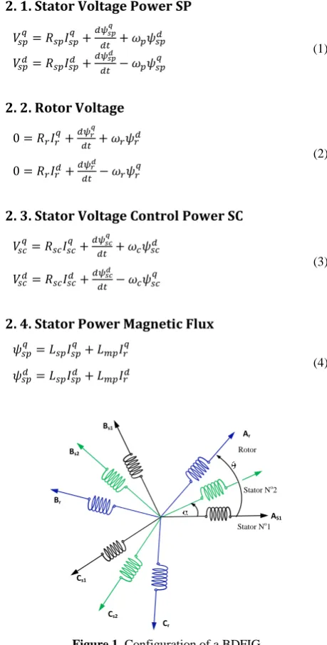
A BDFIG is depicted in Figure 1. The BDFIG dynamic equations in the reference d-q form can be written as follows [3]. The expressions for stators, rotor voltage and flux equations are given below.
2. 1. Stator Voltage Power SP
𝑉𝑠𝑝𝑞= 𝑅𝑠𝑝𝐼𝑠𝑝𝑞 + 𝑑𝜓𝑠𝑝𝑞
𝑑𝑡 + 𝜔𝑝𝜓𝑠𝑝 𝑑
𝑉𝑠𝑝𝑑= 𝑅𝑠𝑝𝐼𝑠𝑝𝑑 + 𝑑𝜓𝑠𝑝𝑑
𝑑𝑡 − 𝜔𝑝𝜓𝑠𝑝
𝑞 (1)
2. 2. Rotor Voltage
0 = 𝑅𝑟𝐼𝑟𝑞+ 𝑑𝜓𝑟𝑞
𝑑𝑡 + 𝜔𝑟𝜓𝑟 𝑑
0 = 𝑅𝑟𝐼𝑟𝑑+𝑑𝜓𝑟
𝑑
𝑑𝑡 − 𝜔𝑟𝜓𝑟 𝑞
(2)
2. 3. Stator Voltage Control Power SC
𝑉𝑠𝑐𝑞= 𝑅𝑠𝑐𝐼𝑠𝑐𝑞 + 𝑑𝜓𝑠𝑐𝑞
𝑑𝑡 + 𝜔𝑐𝜓𝑠𝑐 𝑑
𝑉𝑠𝑐𝑑= 𝑅𝑠𝑐𝐼𝑠𝑐𝑑 + 𝑑𝜓𝑠𝑐𝑑
𝑑𝑡 − 𝜔𝑐𝜓𝑠𝑐 𝑞
(3)
2. 4. Stator Power Magnetic Flux
𝜓𝑠𝑝𝑞 = 𝐿𝑠𝑝𝐼𝑠𝑝𝑞 + 𝐿𝑚𝑝𝐼𝑟𝑞
𝜓𝑠𝑝𝑑 = 𝐿𝑠𝑝𝐼𝑠𝑝𝑑 + 𝐿𝑚𝑝𝐼𝑟𝑑
(4)
Figure 1. Configuration of a BDFIG
Cs1 Bs1
AS1 Ar
Stator No
1 Bs2
Br
Cs2
Cr
Stator No
2. 5. Rotor Magnetic Flux
𝜓𝑟𝑞= 𝐿𝑟𝐼𝑟𝑞+ 𝐿𝑚𝑐𝐼𝑠𝑐𝑞 + 𝐿𝑚𝑝𝐼𝑠𝑝𝑞
𝜓𝑟𝑑= 𝐿𝑟𝐼𝑟𝑑+ 𝐿𝑚𝑐𝐼𝑠𝑐𝑑 + 𝐿𝑚𝑝𝐼𝑠𝑝𝑑
𝜓𝑠𝑐𝑞 = 𝐿𝑠𝑐𝐼𝑠𝑐𝑞 + 𝐿𝑚𝑐𝐼𝑟𝑞
𝜓𝑠𝑐𝑑 = 𝐿𝑠𝑐𝐼𝑠𝑐𝑑 + 𝐿𝑚𝑐𝐼𝑟𝑑
(5)
The stator active and reactive power can be written according to the stator currents as:
𝑃𝑠𝑝= 3 2(𝑉𝑠𝑝
𝑑𝐼
𝑠𝑝𝑑 + 𝑉𝑠𝑝𝑞𝐼𝑠𝑝𝑞)
𝑄𝑠𝑝= 3 2(𝑉𝑠𝑝
𝑞
𝐼𝑠𝑝𝑑 − 𝑉𝑠𝑝𝑑𝐼𝑠𝑝𝑞)
(6)
The electromagnetic torque is given by:
𝑇𝑒𝑚= 3
2(𝑃𝑝. 𝐿𝑚𝑝(𝐼𝑠𝑝 𝑞
. 𝐼𝑟𝑑− 𝐼𝑠𝑝𝑞. 𝐼𝑟𝑞) + 𝑃𝑐𝐿𝑚𝑐(𝐼𝑠𝑐𝑞. 𝐼𝑟𝑑−
𝐼𝑠𝑐𝑑. 𝐼𝑟𝑞))
(7)
3. VECTOR CONTROL STRATEGY OF BDFIG
The objective of the vector control (VC) of BDFIG is to obtain a decoupled control of the active and reactive powers as in DC machines [6]. The vector control of BDFIG consists of making:
𝜓𝑠𝑝𝑑 = 𝜓𝑠𝑝 𝜓𝑠𝑝𝑞 = 0 (8)
The stator flux equation of the winding power becomes:
0 = 𝐿𝑠𝑝𝐼𝑠𝑝 𝑞
+ 𝐿𝑚𝑝𝐼𝑟 𝑞
𝜓𝑠𝑝𝑑 = 𝐿𝑠𝑝𝐼𝑠𝑝𝑑 + 𝐿𝑚𝑝𝐼𝑟𝑑
(9)
By neglecting resistances of the stator phases, the stator voltage will be expressed by:
𝑉𝑠𝑝𝑑= 0
𝑣𝑠𝑝𝑞 = 𝑉𝑠𝑝= 𝜓𝑠𝑝𝑑. 𝜔𝑠𝑝
(10)
From Equation (10), Equation (6) becomes:
𝑃𝑠𝑝= 3 2(𝑉𝑠𝑝
𝑞
𝐼𝑠𝑝𝑞)
𝑄𝑠𝑝=32(𝑉𝑠𝑝𝑞𝐼𝑠𝑝𝑑)
(11)
The rotor currents by:
𝐼𝑠𝑝𝑞 = −𝐿𝑚𝑝
𝐿𝑠𝑝 𝐼𝑟
𝑞
𝐼𝑠𝑝𝑑 =
𝜓𝑠𝑝𝑑−𝐿𝑚𝑝𝐼𝑟𝑑
𝐿𝑠𝑝
(12)
𝐼𝑟𝑞=
𝜓𝑟𝑞−𝐿𝑚𝑝.𝐼𝑠𝑝𝑞−𝐿𝑚𝑐𝐼𝑠𝑐𝑞
𝐿𝑟
𝐼𝑟𝑑=
𝜓𝑟𝑑−𝐿𝑚𝑝.𝐼𝑠𝑝𝑑−𝐿𝑚𝑐𝐼𝑠𝑐𝑑
𝐿𝑟
(13)
We replace the expressions of the currents in Equation (12) we find:
𝐼𝑠𝑝𝑞 (1 − 𝐿𝑚𝑝2
𝐿𝑠𝑝𝐿𝑟) =
−𝐿𝑚𝑝
𝐿𝑠𝑝𝐿𝑟𝜓𝑟
𝑞
+−𝐿𝑚𝑝𝐿𝑚𝑐
𝐿𝑠𝑝𝐿𝑟 𝐼𝑠𝑐
𝑞
𝐼𝑠𝑝𝑑(𝐿𝑠𝑝𝐿𝑟− 𝐿2𝑚𝑝) = 𝐿𝑟𝜓𝑠𝑝𝑑 − 𝐿𝑚𝑝𝜓𝑟𝑑+ 𝐿𝑚𝑝𝐿𝑚𝑐𝐼𝑠𝑐𝑑
(14)
After simplification, we obtain: 𝐼𝑠𝑝
𝑞
= −𝐿𝑚𝑝
𝐿𝑠𝑝.𝐿𝑟−𝐿𝑚𝑝2 𝜓𝑟
𝑞
+ 𝐿𝑚𝑝.𝐿𝑚𝑐
𝐿𝑠𝑝.𝐿𝑟−𝐿𝑚𝑝2 𝐼𝑠𝑐
𝑞
𝐼𝑠𝑝𝑑 =
𝐿𝑟
𝐿𝑠𝑝.𝐿𝑟−𝐿𝑚𝑝2 𝜓𝑠𝑝𝑑 −
𝐿𝑚𝑝
𝐿𝑠𝑝.𝐿𝑟−𝐿𝑚𝑝2 𝜓𝑟𝑑+
𝐿𝑚𝑝.𝐿𝑚𝑐
𝐿𝑠𝑝.𝐿𝑟−𝐿𝑚𝑝2 𝐼𝑠𝑐
𝑑
(15)
where:
𝛿1= 𝐿𝑚𝑝𝐿𝑚𝑐
𝐿𝑠𝑝𝐿𝑟−𝐿2𝑚𝑝, 𝛿2=
𝐿𝑚𝑐𝐿𝑠𝑝
𝐿𝑠𝑝𝐿𝑟−𝐿𝑚𝑝2 , 𝛿3= 𝐿𝑠𝑐−
𝐿𝑚𝑐2 𝐿𝑠𝑝
𝐿𝑠𝑝𝐿𝑟−𝐿2𝑚𝑝
𝛿4= 𝐿𝑚𝑝
𝐿𝑠𝑝𝐿𝑟−𝐿2𝑚𝑝, 𝛿5=
𝐿𝑟
𝐿𝑠𝑝𝐿𝑟−𝐿2𝑚𝑝
(16)
The stator active and reactive powers can be written according to the stator currents as:
𝑃𝑠𝑝= 3 2𝑉𝑠𝑝
𝑞[−𝛿
4𝜓𝑟𝑞+ 𝛿1𝐼𝑠𝑐𝑞]
𝑄𝑠𝑝= 3 2𝑉𝑠𝑝
𝑞
[𝛿5𝜓𝑠𝑝𝑑 − 𝛿4𝜓𝑟𝑑+ 𝛿1𝐼𝑠𝑐𝑑]
(17)
We replace the expression of the current (𝐼𝑟𝑑, 𝐼𝑟 𝑞
) of
Equation (13) in Equation (5), we obtain:
𝜓𝑠𝑐𝑞 = 𝐿𝑠𝑐𝐼𝑠𝑐𝑞 + 𝐿𝑚𝑐(
𝜓𝑟𝑞−𝐿𝑚𝑝𝐼𝑠𝑝𝑞−𝐿𝑚𝑐𝐼𝑠𝑐𝑞
𝐿𝑟 )
𝜓𝑠𝑐𝑑 = 𝐿𝑠𝑐𝐼𝑠𝑐𝑑 + 𝐿𝑚𝑐(
𝜓𝑟𝑑−𝐿𝑚𝑝𝐼𝑠𝑝𝑑−𝐿𝑚𝑐𝐼𝑠𝑐𝑑
𝐿𝑟 )
(18)
We put the current expression (𝐼𝑠𝑝 𝑞
, 𝐼𝑠𝑝𝑑)of Equation (15)
in Equation (18), we obtain:
2 2
2 2 2
.
. .
.
.
. . .
mp mp mc
q q q
r mp r sc
q q mc
sp r mp sp r mp sc sc sc
r q mc sc
mp mp mc
d r d d d
r mp sp r sc
d d mc
sp r mp sp r mp sp r mp sc sc sc
r d mc sc
L L L
L I
L
L L L L L L
L I L
L I
L L L
L
L I
L
L L L L L L L L L
L I L L I − − + − − = + − − − + − − − = + − (19) Finally:
𝜓𝑠𝑐𝑞 = 𝛿3𝐼𝑠𝑐𝑞 + 𝛿2𝜓𝑟𝑞
𝜓𝑠𝑐𝑑 = 𝛿3𝐼𝑠𝑐𝑑 + 𝛿2𝜓𝑟𝑑− 𝛿1𝜓𝑠𝑝𝑑
(20)
We put the expression of the flux (𝜓𝑠𝑐 𝑞
, 𝜓𝑠𝑐𝑑) in Equation
(3), we obtain the stator voltage as follows:
𝑉𝑠𝑐𝑞= 𝑅𝑠𝑐𝐼𝑠𝑐𝑞 + 𝑑 𝑑𝑡(𝛿3𝐼𝑠𝑐
𝑞
+ 𝛿2𝜓𝑟𝑞) + 𝜔𝑐(𝛿3𝐼𝑠𝑐𝑑 +
𝛿2𝜓𝑟𝑑− 𝛿1𝜓𝑠𝑝𝑑)
𝑉𝑠𝑐𝑑= 𝑅𝑠𝑐𝐼𝑠𝑐𝑑 + 𝑑 𝑑𝑡(𝛿3𝐼𝑠𝑐
𝑑 + 𝛿
2𝜓𝑟𝑑− 𝛿1𝜓𝑠𝑝𝑑) −
𝜔𝑐(𝛿3𝐼𝑠𝑐𝑞 + 𝛿2𝜓𝑟𝑞)
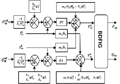
Block diagram of the vextor control of BDFIG is shown in Figure 2.
4. SLIDING MODE CONTROL
Sliding mode control has been widely used in robust control approaches in many non-linear control method, the basic idea that if we can force a system to evolve towards an equilibrium point according to a dynamic chosen by the designer using the continuous control law.
The proposed sliding surface is used in this work [8]:
𝑆(𝑥) = (𝑑
𝑑𝑡+ 𝜆)
𝑛−1× 𝑒 (22)
𝜆: is a positive coefficient,
𝑒 = 𝑥𝑑− 𝑥: is the error,
𝑥𝑑: is the desired state,
n: is the system order.
4. 1. Switching Surface Let the monovariable
dynamic system described by the following state equation [8]:
( , ) ( , ). ( , )
x= f x t +B x t u x t (23)
where:xRnis the state variable,
u
(
x
,
t
)
R
nis the control vector, B(x,t)are system parameter. The generalized SMC law is given as:( ( , )) n eq
n
U U U
U K sign s x t
= +
= (24)
where, U is the control vector, Ueq is the equivalent
control vector, sign is the signum function, K is the controller gain, s is the sliding surface. Figure 3 shows the sliding mode control block.
Figure 2. Block diagram of the vector control of BDFIG
Figure 3. Sliding mode control block.
4. 2. Indirect Power Control with SMC of a BDFIG
In this section, the sliding surfaces are designed according to the current references of the stator control. The objective of this design is to independently control the generated active and reactive powers.
4. 2. 1. Choice of the Sliding Surface Control
Two sliding currents surfaces are used a first order is defined as:
𝑆(𝐼𝑠𝑐𝑞) = (𝐼𝑠𝑐 𝑞𝑟𝑒𝑓
− 𝐼𝑠𝑐𝑞)
𝑆(𝐼𝑠𝑐𝑑) = (𝐼𝑠𝑐 𝑑_𝑟𝑒𝑓
− 𝐼𝑠𝑐𝑑)
(25)
where 𝐼𝑠𝑐 𝑞_𝑟𝑒𝑓
, 𝐼𝑠𝑐 𝑑_𝑟𝑒𝑓
are the expected currents of control power reference.
We have voltages in Equation (21), it can be used to extract the expressions of control current:
2 3 2 1
3
2 3 2
3
1
( )
1
( )
q
q q q d d d
sc sc sc sc r c sc r sp
d
d d d q q
sc sc sc sc r c sc r
I V R I I
I V R I I
= − − − + −
= − − + +
(26)
5. CONDITIONS OF CONVERGENCE OF THIS CONTROL
To guarantee the convergence of the selected variables towards the references, the two sliding surfaces must be zero as follows:
𝑆(𝐼𝑠𝑐𝑞𝑟𝑒𝑓
− 𝐼𝑠𝑐𝑞) = 0 ⇒ 𝑑 𝑑𝑡(𝐼𝑠𝑐
𝑞𝑟𝑒𝑓
− 𝐼𝑠𝑐𝑞) = 0
𝑆(𝐼𝑠𝑐𝑑_𝑟𝑒𝑓− 𝐼𝑠𝑐𝑑) = 0 ⇒ 𝑑 𝑑𝑡(𝐼𝑠𝑐
𝑑_𝑟𝑒𝑓
− 𝐼𝑠𝑐𝑑) = 0
(27)
The sliding area of the current control can be defined as follows:
_
_
( ) ( )
( ) ( )
q ref q q
sc sc
sc
d ref d d
sc sc
sc
S I I I
S I I I
= −
= −
(28)
_
2 3 2 1
3
_
2 3 2
3
1
( ) ( )
1
( ) ( )
q ref
q q q q d d d
sc
sc sc sc sc r c sc r sp
d ref
d d d d q q
sc
sc sc sc sc r c sc r
S I I V R I I
S I I V R I I
•
= − − − − + −
= − − − + +
5. 1. Control Law The satisfactions of the control voltage and sign function are presented in the following:
𝑉𝑠𝑐𝑑= 𝑉𝑠𝑐𝑑_𝑒𝑞+ 𝑉𝑠𝑐𝑑_𝑎𝑡𝑡
𝑉𝑠𝑐𝑑𝑎𝑡𝑡= 𝐾𝑑× 𝑠𝑖𝑔𝑛(𝑠(𝑥, 𝑡))
𝑉𝑠𝑐𝑞= 𝑉𝑠𝑐 𝑞𝑒𝑞
+ 𝑉𝑠𝑐𝑞𝑎𝑡𝑡
𝑉𝑠𝑐𝑞_𝑎𝑡𝑡= 𝐾𝑞× 𝑠𝑖𝑔𝑛(𝑠(𝑥, 𝑡))
(30)
with
𝑉𝑠𝑐𝑑, 𝑉𝑠𝑐 𝑞
: Control vectors relation. 𝑉𝑠𝑐
𝑑_𝑒𝑞
, 𝑉𝑠𝑐 𝑞_𝑒𝑞
: Equivalent control vectors relation.
𝑉𝑠𝑐𝑑_𝑎𝑡𝑡, 𝑉𝑠𝑐
𝑞_𝑎𝑡𝑡
: Switching control. 𝐾𝑑, 𝐾𝑞 : Positive constant.
From Equation (29), the voltage equivalent control is given by:
𝑆•(𝐼𝑠𝑐𝑞) = 0 ⇒ 𝑉𝑠𝑐𝑞𝑒𝑞
= 𝛿3𝐼 • 𝑠𝑐 𝑞𝑟𝑒𝑓
+ 𝑅𝑠𝑐𝐼𝑠𝑐 𝑞
+ 𝛿2𝜓
• 𝑟 𝑞
+ 𝜔𝑐(𝛿3𝐼𝑠𝑐𝑑 + 𝛿2𝜓𝑟𝑑− 𝛿1𝜓𝑠𝑝𝑑)
𝑆•(𝐼𝑠𝑐𝑑) = 0 ⇒ 𝑉𝑠𝑐𝑑_𝑒𝑞= 𝛿3𝐼 •
𝑠𝑐𝑑_𝑟𝑒𝑓+ 𝑅𝑠𝑐𝐼𝑠𝑐𝑑 +
𝛿2𝜓 •
𝑟𝑞− 𝜔𝑐(𝛿3𝐼𝑠𝑐𝑞 + 𝛿2𝜓𝑟𝑞)
(31)
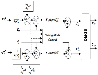
The global BDFIG sliding-mode control are depicted in Figure 4.
6. NEURO-FUZZY ARCHITECTURE
Hybrid systems that combine fuzzy logic, neural networks, genetic algorithms, and expert systems have proven their effectiveness in a variety of real-world problems and in industry. Each intelligent technique has specific properties. Each technique is suitable for solving certain particular problems. In fact, neural networks are used for the recognition of models. However, they are unable to explain how they reach their decisions. Fuzzy logic systems can reason with imprecise information and
Figure 4. Block diagram of BDFIG sliding mode control
explain their decisions but cannot, however, automatically acquire the rules they used to make those decisions. These limits have been a reason behind the creation of intelligent hybrid systems where; two or more techniques are combined to overcome the limitations of one technique [23].
Adaptive neural based on fuzzy inference system ANFIS uses feedback learning to determine the input parameters and parameters used. Each step of the iterative learning algorithm has two parts. In the first part, the input models are propagated and the parameters of the parameters are calculated using the iterative minimal square method algorithm, while the parameters of the premises are considered fixed. In the second part, the input models are propagated again, and at each iteration, the back propagation learning algorithms are used to modify the parameters of the premises, while the consequences remain fixed.
6. 1. Adaptive Neuro-fuzzy Sliding Mode Control
Inference System A typical diagram of a
ANFIS is shown in Figure 5, in which a circle indicates a fixed node on one hand, and a square implies an adaptation node on the other hand [13]. In addition, x, y stand for two inputs and one output, Sugeno fuzzy is often used in various fuzzy inference models for the following reasons: high interpretability, increased efficiency and adaptation techniques where the number of epochs is set to 40 and error tolerance of 10-6 [23].
The direct current error (e, de) is two inputs of ANFIS control in our system defined as:
𝑒 = 𝐼𝑠𝑐𝑞𝑟𝑒𝑓
− 𝐼𝑠𝑐𝑞 → 𝑑𝑒 = 𝐼𝑠𝑐𝑞𝑟𝑒𝑓
− 𝐼𝑠𝑐𝑞
𝑒 = 𝐼𝑠𝑐𝑑_𝑟𝑒𝑓− 𝐼𝑠𝑐𝑑 → 𝑑𝑒 = 𝐼𝑠𝑐 𝑑_𝑟𝑒𝑓
− 𝐼𝑠𝑐𝑑
(32)
where, (e,de) is the first order Sugeno case fuzzy inference employed by ANFIS, and the function fuzzy rule is:
If 𝑒is 𝐴𝑖and 𝑑𝑒is 𝐵𝑖then y=f(e,de). Corresponding to the
architecture of ANFIS which consists of five layers. The steps of ANFIS structure are:
Layer 1: Each corresponding node during this layer creates the membership range for the input vectors Ai,
i=1….7.
Layer 2: The node generates the crossing by multiplying all the incoming signals:𝑂𝑖2= 𝑤𝑖= 𝜇𝐴𝑖(𝑥)𝜇𝐵𝑖(𝑦), for
𝑖 = 1, . . .49.
Average nodes (Layer 3): Divided by the sum of all other entries.
𝑂𝑖3= 𝑤𝑖= 𝑤 ∑49𝑖=1𝑤𝑖
(33)
Consequent nodes (Layer 4): Compute the contribution of the i-th rule in the output with the following node function.
𝑂𝑖4= 𝑤𝑖𝑦𝑖= 𝑤𝑖(𝑝𝑖𝑒 + 𝑞𝑖𝑑𝑒 + 𝑟𝑖)
where, 𝑤𝑖 is the output of layer 3, and (pi, qi, ri) are the
parameter set of the ‘i-th’ node.
Output node (Layer 5): The neuron of layer 5 is a fixed neuron, at a given input; it delivers the network response given by:
𝑂𝑖5= ∑ 𝑤 𝑖 49 𝑖=1 𝑓𝑖 =
∑49𝑖=1𝑤𝑖𝑓𝑖
∑49𝑖=1𝑤𝑖
(34)
6. 2. Description of the Control System
Figure 6 shows the proposed Neuro-Fuzzy-Sliding Mode Control for controlling the active and reactive powers of the BDFIG. NFSMC controller replaces the switching control of SMC, the first input is the error of the current and the second input is the derivative of the error. Figure 6 shows the neuro-fuzzy sliding mode control
7. SIMULATION RESULTS
Different power control methods have been studied and modeled with Matlab / Simulink software under the same test conditions powered by an PWM inverter. Simulations were applied to the 2.5 kW BDFIG system incorporating the NFSMC compared with the SMC and PI control. The parameters of the BDFIG system are illustrated and appended to Table 1 where the speed is fixed at 73 rad /s.
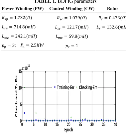
Figure 7 presents the NFSMC test with training and cheking of reactive and active power reference error data sets after 40 epochs to guarantee good performance of results.
Figures 8 and 9 show the active and reactive powers produced by BDFIG with the different control strategies,VC, SMC and NFSMC. In these figures, we
Figure 6. Neuro-Fuzzy-Sliding Mode Control
TABLE 1. BDFIG parameters
Power Winding (PW) Control Winding (CW) Rotor
𝑅𝑠𝑝= 1.732(𝛺) 𝑅𝑠𝑐= 1.079(𝛺) 𝑅𝑟= 0.473(𝛺)
𝐿𝑠𝑝= 714.8(𝑚𝐻) 𝐿𝑠𝑐= 121.7(𝑚𝐻) 𝐿𝑟= 132.6(𝑚𝐻)
𝐿𝑚𝑝= 242.1(𝑚𝐻) 𝐿𝑚𝑐= 59.8(𝑚𝐻)
𝑝𝑝= 3; 𝑃𝑛= 2.5𝐾𝑊 𝑝𝑐= 1
Figure 7. NF-SMC training and checking error of active power
Figure 8. Reactive power response
Figure 9. Active power response under VC, SMC and NFSMC strategies
can notice that the ripple is not the same for the three techniques, it is clear that the VC suffers from two problems: stabilizing error and high ripples in the active power. On the other hand, the NFSMC offers an almost
0 5 10 15 20 25 30 35 40
0 5 10 15x 10
11
Epoch
C
h
e
c
h
a
n
d
T
r
E
r
r
Ttraining-Err Checking-Err
0 0.5 1 1.5 2 2.5 3
-1500 -1000 -500 0 500
Time(s)
Q
s
[
v
a
r
]
SMC PI Ref NFSMC
0.795 0.8 0.805
-1000 -500 0
0 0.5 1 1.5 2 2.5 3
-1500 -1000 -500 0 500
Time(s)
P
s
[
w
]
SMC PI Ref NFSMC
1.296 1.298 1.3 1.302 1.304 1.306 -1000
perfect behavior in terms of performance and good follow-up compared to the PI and SMC.
Figure 10 shows the stator current on phase A, with sinusoidal shapes for the three strategies. We can observe that the current ripple also has a significant reduction of the NFSMC controller compared to the other controller.
7. 1. Simulation Results with Parametric
Uncertainty To study the influence of the
electrical parameter variation on the behavior of the BDFIG, we also simulated the system for a +100% of the nominal stator resistance at time t = 2.5s.
Figures 11 and 12 illustrate the evolution of the powers. We note from this result that the scheme (PI) has a slight variation due to the variations of stator resistance. The proposed NFSMC method is robust against parameter variations and allows a fast and suitable dynamic response.
Figure 10. Stator current Isa of three approaches
Figure 11. Reactive power under stator resistance variation
Figure 12. Active power under stator resistance variation
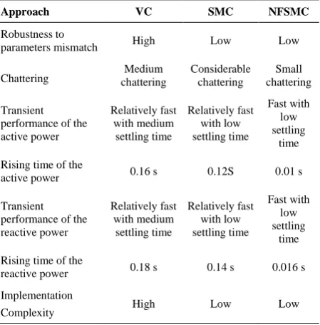
Table 2 presents the quantitative analysis of the three approaches. The comparison implicates that the proposed NFSMC gives less chattering with a seamless transient response.
TABLE 2. Performances comparison of the three controllers
Approach VC SMC NFSMC
Robustness to
parameters mismatch High Low Low
Chattering chattering Medium Considerable chattering chattering Small
Transient performance of the active power
Relatively fast with medium settling time
Relatively fast with low settling time
Fast with low settling
time
Rising time of the
active power 0.16 s 0.12S 0.01 s
Transient performance of the reactive power
Relatively fast with medium settling time
Relatively fast with low settling time
Fast with low settling
time
Rising time of the
reactive power 0.18 s 0.14 s 0.016 s
Implementation
Complexity High Low Low
8. CONCLUSION
In this paper, Neuro-Fuzzy Sliding Mode Control NFSMC for BDFIG has been presented. The suggested control has been compared with the classical vector control based on PI controller and sliding mode control. Simulation results demonstrate that the powers’ ripples is lower in NFSMC compared with the other controls. The efficiency of the proposed NFSMC has been validated by simulation tests carried out with a 2.5 KW BDFIG system. Moreover, to validate the influence of BDFIG parameter variations on the performances of the proposed NFSMC, sensitivity of the stator resistance parameter has been tested for the three schemes for +100% variations in stator resistance. It has been shown that the proposed approach is robust and capable to reject the influences of uncertainty in system parameters.
9. REFERENCES
1. Protsenko, K. and Xu, D., "Modeling and control of brushless doubly-fed induction generators in wind energy applications".
IEEE Transactions on Power Electronics, Vol.23, No3, (2008),
1191–1197.
2. Tazil, M., Kumar, V., and Kong, S. "Three-Phase doubly fed induction generator: An over view", IET Electric Power
Application, (2009), 75–89.
0 0.5 1 1.5 2 2.5 3
-5 0 5
Time(s)
Is
[A
]
SMC PI NFSMC
0 0.5 1 1.5 2 2.5 3
-1500 -1000 -500 0 500
Time(s)
Q
s
[
v
a
r
]
SMC PI Ref NFSMC
2.5 2.55 2.6 -600 -400 -200
0
0.5
1
1.5
2
2.5
3
-1500
-1000
-500
0
500
Time(s)
P
s
[
w
]
2.5 2.55 2.6 -1400 -1200 -1000
3. Jing, C., Xuefan, W., Tantan, Z., Zhenping, L., Ming, K. and,Pengcheng, N., "Application of Brushless Doubly-Fed Machine System Hydropower Generation". 2nd International
Conference on Electrical Machines and Systems (ICEMS). IEEE, (2019), 1-4.
4. Sheng, H., and Guorong Z., "A Vector Control Strategy of Grid-Connected Brushless Doubly Fed Induction Generator Based on the Vector Control of Doubly Fed Induction Generator", 2016 IEEE Applied Power Electronics Conference and Exposition (APEC).
5. Chen, J. F., Zhang, W., Chen, B. J., and Ma, Y. L., "Improved vector control of brushless doubly fed induction generator under unbalanced grid conditions for offshore wind power generation",
IEEE Trans. Energy Conv. Vol.31, (2016), 293-302.
6. Shiyi, S. , Ehsan, A. , Farhad, B. , and Richard, M., "Stator-Flux-Oriented Vector Control for Brushless Doubly Fed Induction Generator", IEEE Transactions on Industrial Electronics, Vol. 56,(2009),4220 – 4228.
7. Mahboub, M. A, and Drid, S. "Sliding mode control of a Brushless doubly fed induction generator", Proceedings of IEEE (ICSC) the 3rd Intel Conference on Systems and Control, Algeria, 2013. 8. Mazouz, F., Belkacem, S., Colak, I., and Drid, S., "Direct Power
Control of DFIG by Sliding Mode Control and Space Vector Modulation", 7th International conference on system and control,
IEEE (ICSC), Valencia – Spain, October, (2018),24-30. 9. Daoud, A., and Derbel, N., "Direct Power Control of DFIG Using
Sliding Mode Control Approach",In Modeling, Identification and Control Methods in Renewable Energy Systems Springer, Singapore, (2019), 193-204.
10. Douadi, T., Y. Harbouche, R. Abdessemed, and I. Bakhti, "Improvement performances of active and reactive power control applied to DFIG for variable speed wind turbine using sliding mode control and FOC." International Journal of Engineering- Transactions A: Basics, Vol. 31, No.10, (2018), 1689-1697.
11. Yang, J., Jian, Y., Weiy, T., Guanguan, Z., Yao, S., Sul, A., and Frede, B., "Sensorless Control of Brushless Doubly Fed Induction Machine Using a Control Winding Current MRAS Observer." IEEE Transactions on Industrial Electronics, Vol. 66, No.1, (2019), 728-738.
12. Juan, I., T, Paul, F.P., Marcelo, G.C., and José, A.,"A Dual-Stator Winding Induction Generator Based Wind-Turbine Controlled via Super-Twisting Sliding Mode". Energies, Vol.12, (2019, 223-230.
13. Roberto, C., Pena, R. , Wheeler, and Clare, P.,"Control of a wind generation system based on a Brushless Doubly-Fed Induction Generator fed by a matrix converter", Electric Power Systems
Research, Vol.103, (2013), 49–60.
14. Maryam, M., Rasool, K., and Mohammad, R.A. "Model-based predictive direct power control of brushless doubly fed reluctance generator for wind power "Alexandria Engineering Journal, Vol. 55, (2016), 2497-2507.
15. Mahyar, G., Ashknaz, O., Sajjad, T., Hashem, O., and Richard A.M., "An analytical study for low voltage ride through of the brushless doubly-fed induction generator during asymmetrical voltage dips" Renewable Energy, Vol. 115, 2018, 64-75.
16. Belkacem, S., Naceri, F., and Abdessemed, R., "Reduction of torque ripple in DTC for induction motor using input-output feedback linearization", Turkish Journal of Electrical
Engineering & Computer Sciences, Vol. 20, No. 3,
( 2012).1123-1130.
17. Youb, L., Belkacem, S, Naceri, F, Cernat, M, and Guasch, L. P, "Design of an Adaptive Fuzzy Control System for Dual Star Induction Motor Drives", Advances in Electrical and Computer
Engineering, Vol. 18, No. 3, (2018).
18. Larbi, D. and Loukianov, A.G. , "Neural Sliding Mode Control of a DFIG Based Wind Turbine with Measurement Delay",
International Federation of Accountants ,Vol. 51, (2018),
456-461.
19. Abdelbasset, M., Drid, S., Sid, M.A., and Ridha, C. "Robust direct power control based on the Lyapunov theory of a grid-connected brushless doubly fed induction generator". Frontiers in Energy, Vol.10, (2016), 298-307.
20. Tiwari, N. K, Parveen, S., Bhupendra, K. S., Subodh, R, and Krishna, K. S."Estimation of Tunnel Desilted Sediment Removal Efficiency by ANFIS. Iranian Journal of Science and
Technology, Transactions of Civil Engineering, (2019), 1-16.
21. Asar, M. F., Elawady, W M., and Sarhan, A M. "ANFIS-based an adaptive continuous sliding-mode controller for robot manipulators in operational space". Multibody System Dynamics, (2019), 10-21.
22. Sana, B., and Anis, S., "Adaptive Neuro-Fuzzy Sliding Mode Controller", International Journal of System Dynamics Applications, Vol. 7, (2018).
23. Ifte, K.A., Uddin, M.N. , and Marsadek, M. "ANFIS Based Neuro-Fuzzy Control of DFIG for Wind Power Generation in Standalone Mode", 2019 IEEE International Electric Machines & Drives Conference (IEMDC).
24. Ibrahim, F.B., Ahmed, A., Ahmed, T., an d Ahmed, L., "Robust neuro-fuzzy sliding mode control with extended state observer for an electric drive system". Energy, Vol. 169, (2018). 25. Mazouz, F., Belkacem, S., Drid, S., Chrifi, A.L. and Colak I.,
"Fuzzy Sliding Mode Control of DFIG applied to the WECS". Proceedings of the 8th International Conference on Systems and
Neuro-fuzzy Sliding Mode Controller Based on a Brushless Doubly Fed Induction
Generator
L. Ouadaa, S. Benaggounea, S. Belkacemb
a Faculty of Technology, LSTE Laboratory, University of Mostefa Ben Boulaïd Batna 2, Algeria
b LEB Research Laboratory, Electrical Engineering Department, University of Mostefa Ben Boulaïd Batna 2, Algeria
P A P E R I N F O
Paper history:
Received 30 June 2019
Received in revised form 07 January 2020 Accepted 16 January 2020
Keywords:
Brushless Doubly Fed Induction Generator Neuro-fuzzy Sliding Mode Control Parameters Uncertainly Sliding Mode Control Vector Control هدیکچ کرت یب ی هکبش زا اه ی بصع ی لرتنک و هدننک اه ی زاف ی رتدمآراک ناونع هب ی ن ارب شور ی رقت ی ب باوت ع هدش هتفرگ رظن رد فلتخم
ناشن و تسا اناوت هدنهد
یی س لرتنک رد اهنآ ی متس اه ی د ی مان ی ک ی غ ی طخر ی ا رد .تسا ی ن هلاقم ی ک ژتارتسا ی کرت لرتنک یب ی هب
وشک تلاح لرتنک مان یی
Neuro-Fuzzy (NFSMC)
نتبم ی اقلا روتارنژ رب یی
ذغت ی ه هدش
Brushless Dushly
(BDFIG)
ا .تسا هدش هئارا ی ن اج ی زگ ی ن وشک حطس یی م لرتنک ی دپ ات دوش ی هد
chattering
شان ی لرتنک درکلمع زا
پان ی هتسو ا .دنک فذح ار ی ن نکت ی ک و ی گژ ی اه ی باذج ی غت هب تمواقم دننام یی
تار م هئارا ار رتماراپ ی اتن .دهد ی بش ج ی ه زاس ی 2.5 KW BDFIG ارب ی أت یی د شخبرثا ی ور ماکحتسا و ی درک پ ی داهنش ی عطق مدع روضح رد ی
ت رادرب لرتنک اب هطبار رد
(VC)
وشک تلاح لرتنک و یی
(SMC)
صوصخ ام .تسا هدش هئارا ی تا تاتسا ی ک د و ی مان ی ک ی ارش تحت ار لرتنک شور هس ی ط لمع ی تا ی ی ناسک پ نامه رد و ی دنبرک ی بش ی ه زاس ی اقم ی هس م ی نک ی م حرط . اه ی لرتنک پ هدننک ی داهنش ی (NFSMC) شهاک رد تردق جوم اه ی شنکاو و لاعف ی
دنتسه رثؤم ، تلاح بوکرس رثؤم روط هب اه ی وشک یی عطق مدع تارثا و ی ت اه ی رتماراپ ی رب س درکلمع ی متس ن رثؤم ی دنتس .