Iranian Journal of Electrical & Electronic Engineering, Vol. 14, No. 1, March 2018 37
Development and Analysis of a Novel Multi-Mode MPPT
Technique with Fast and Efficient Performance for
PMSG-Based Wind Energy Conversion Systems
S. Heshmatian*, D. Arab Khaburi*(C.A.), M. Khosravi* and A. Kazemi*
Abstract: Wind energy is one of the most promising renewable energy resources. Due to instantaneous variations of the wind speed, an appropriate Maximum Power Point Tracking (MPPT) method is necessary for maximizing the captured energy from the wind at different speeds. The most commonly used MPPT algorithms are Tip Speed Ratio (TSR), Power Signal Feedback (PSF), Optimal Torque Control (OTC) and Hill Climbing Search (HCS). Each of these algorithms has some advantages and also some major drawbacks. In this paper, a novel hybrid MPPT algorithm is proposed which modifies the conventional methods in a way that eliminates their drawbacks and yields an improved performance. This proposed algorithm is faster in tracking the maximum power point and provides a more accurate response with lower steady state error. Moreover, it presents a great performance under conditions with intensive wind speed variations. The studied Wind Energy Conversion System (WECS) consists of a Permanent Magnet Synchronous Generator (PMSG) connected to the dc link through a Pulse-Width Modulated (PWM) rectifier. The proposed algorithm and the conventional methods are applied to this WECS and their performances are compared using the simulation results. These results approve the satisfactory performance of the proposed algorithm and its notable advantages over the conventional methods.
Keywords: Maximum Power Point Tracking (MPPT), Permanent Magnet Synchronous Generator (PMSG), Pulse-Width Modulated (PWM) Rectifier, Variable-Speed Wind Turbine, Wind Energy Conversion System (WECS).
1 Introduction1
OWADAYS, a lot of attention is directed towards renewable energy resources due to various reasons such as reduction of fossil fuel recourses, high rate of population growth, fast development of various industries and global environmental issues. Wind energy is one of the most promising and developed resources of green energy [1]. A typical Wind Energy Conversion System (WECS) primarily consists of wind
Iranian Journal of Electrical & Electronic Engineering, 2018. Paper first received 02 September 2017 and accepted 22 February 2018.
* The authors are with the Electrical Engineering Department, Iran University of Science and Technology (IUST), Tehran, Iran. E-mails: [email protected], [email protected],
[email protected] and [email protected]. Corresponding Author: D. Arab Khaburi.
turbine, electric generator, power electronic interface and its corresponding control system.
Doubly Fed Induction Generator (DFIG) was the dominant technology in the market for a long time. However, in recent years, more and more attention has been paid to gearless direct-driven systems which mainly utilize Permanent Magnet Synchronous Generators (PMSG) [2,3]. This is due to their notable advantages such as: low maintenance, high power density, high efficiency, elimination of slip rings and the external excitation system, low weight and volume and high reliability [4,5].
Moreover, an appropriate power electronic interface is needed for connecting a WECS to the load or utility grid. This interface mainly consists of generator-side and grid-side converters. A controllable active H-bridge rectifier is used in this work as the generator-side converter. One of the main concerns regarding control
N
Iranian Journal of Electrical & Electronic Engineering, Vol. 14, No. 1, March 2018 38 of the generator-side converter is to capture the
maximum attainable energy from the wind, since it has an unpredictable nature. Many different algorithms have been proposed for tracking the Maximum Power Point (MPP). The main methods are Tip Speed Ratio (TSR), Power Signal Feedback (PSF), Optimal Torque Control (OTC) and Perturbation and Observation (P&O), also known as Hill-Climbing Search (HCS) [6,7].
In the TSR algorithm, the generator rotational speed reference is determined by keeping the tip speed ratio at its optimal value [8,9]. Although this method is simple and fast, but it is not accurate enough in tracking the maximum power point. This is due to the inherent inaccuracy of the effective wind speed measurement [7]. The OTC method adjusts the generator torque to its optimal value obtained from the optimum torque-speed curve of the system [8,10]. The PSF method has a principle similar to the OTC algorithm. In this method, the optimal power-speed curve is used as a look-up table or a mathematical expression in order to determine the optimal power reference required for tracking the maximum power point [11]. The PSF and OTC methods, although do not need wind speed measurement, but require knowledge of the system parameters and air density. Optimal characteristic curves are also required which will change as the system ages [6,12].
P&O searching algorithm is widely utilized in order to implement MPPT in WECSs [13,14]. This algorithm is a simple and efficient method since prior knowledge of the system parameters or wind speed measurement are not required [7,10]. However, it has one main drawback which lies in the fact that choosing the right perturbation step size is a challenging task in this method. P&O algorithm with a large step size causes oscillations around the optimum point and hence, the MPPT accuracy and efficiency will be reduced. On the other hand, using a small step size although decreases the oscillations, but also leads to a low convergence speed [6,15]. Another important drawback of this method is that it is deficient in larger systems, especially under rapid wind variations [7], because it is slow and cannot keep up in these conditions to efficiently track the optimum point. Two-step-value HCS algorithm is proposed in [16,17] in order to improve the performance of this method. Variable step size has also been considered in order to overcome the aforementioned conflicting problem of conventional HCS method [18]. These methods, although improve the performance of HCS algorithm, but do not have completely satisfactory performance especially under rapid wind speed variations.
In addition to the aforementioned MPPT algorithms, some other methods have also been proposed. Fuzzy logic has been employed for implementing variable step size HCS algorithm [19,20]. However, performance of the fuzzy logic-based MPPT methods depends a lot on the knowledge and experience of the user in
determining the membership functions and also the rule base. Some efforts have been made in order to use neural networks for realization of MPPT in WECSs [21,22]. Sliding Mode Control (SMC) has also been applied to WECSs for maximizing the captured energy [20,23]. These methods although can improve the MPPT performance in comparison to the conventional methods, but impose a notable amount of computational burden and complexity to the control system.
In this paper, a novel hybrid MPPT algorithm is proposed. This algorithm includes three modes, which are chosen to be used based upon the wind speed variations. If the wind speed is constant or has smooth variations in a time period, the algorithm will operate in the first or the second mode and if the wind speed varies rapidly and intensively, the algorithm will switch to the third mode. This strategy has great performance under different conditions and is advantageous over the conventional methods in terms of providing fast and accurate responses, especially under intensive wind variations. Moreover, this proposed method has less complexity and also it is much easier to be implemented compared to artificial intelligence-based methods.
2 System Description
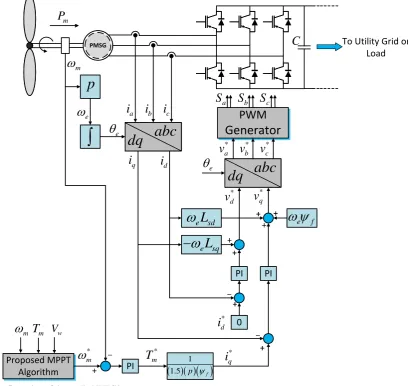
The configuration of the studied WECS is depicted in Fig. 1, which consists of a direct-driven PMSG connected to an active Pulse-Width Modulated (PWM) rectifier. The proposed MPPT algorithm generates the appropriate rotational speed reference. This reference is compared with the real rotor speed, and the error signal is fed to a Proportional-Integral (PI) controller in order to generate the torque, and subsequently the q-axis current reference. The reference of the d-axis current is set to zero. Finally, the appropriate voltage references are determined and fed to a PWM generator to provide the switching pulses for the converter.
2.1 Wind Turbine Model
For a variable-speed wind turbine, the mechanical output power is given by the following expression.
3 1
2
m P w
P C AV (1)
where Pm is the mechanical power, CP is power coefficient, ρ is the air density, A is the swept area by the blades and Vw is the wind speed. The power coefficient is described by a non-linear function of tip speed ratio (λ) and pitch angle of the turbine blades (β) as the following equations [24].
51
1 2 3 4 6
1
, i
k P
i
C k k k k e k
(2)
3
1 1 0.035
0.08 1
i
(3)
Iranian Journal of Electrical & Electronic Engineering, Vol. 14, No. 1, March 2018 39 The values of the ki coefficients in Eq. (2) are given in
Table 1. The tip speed ratio is defined as the ratio between the blade tip speed and the effective wind speed upstream the blades.
m w R
V
(4)
where ωm is the generator mechanical angular speed and
R is the radius of the blades. The swept area by the blades is as Eq. (5).
2
AR (5)
The CP–λ curves for the studied wind turbine are depicted for different pitch angle values in Fig. 2. As it is obvious from this figure, the corresponding curve to
β = 0 has the greatest peak value. This peak value occurs at λopt = 8.1 and equals to
max
P
C = 0.48. Therefore,
the pitch angle of the studied turbine is assumed to be fixed at β = 0 herein forward. The mechanical equation of the turbine is as the following expression.
m
m e m
d
J T T F
dt
(6)
where Tm is the mechanical torque provided by the wind turbine and Te is the electromagnetic torque of the electric generator. J is total inertia and F is the friction factor of the rotor.
2.2 PMSG Model
The dynamic model of PMSG can be described in the direct-quadrature (dq) synchronous reference frame as the following form [25]:
0 1
1 0
sd sd sd sd
s e
sq sq sq sq
v i d
R
v i dt
(7)
where vsd, vsq, isd, isq , Ψsd, and Ψsq represent direct and
quadrature components of the stator voltage, current and flux, respectively. Rs is the resistance of stator winding and ωe is the generator electrical angular speed, which is related to the mechanical angular rotational speed (ωm) by the following equation.
Proposed MPPT
Algorithm PI
PMSG PMSG
PI PI
0
PWM
Generator
p
1.5 1p
fabc
dq
dq
abc
e
L
sd
e
L
sq
e f
m
T
m Vw* m
*m
T
*q
i
* d
i
* d
v
v
*q* a
v
v
b*v
*ca
S
S
bS
ca
i
i
bi
cq
i
i
dm
e
e
e
C
m
P
To Utility Grid or Load
Fig. 1 Configuration of the studied WECS.
Iranian Journal of Electrical & Electronic Engineering, Vol. 14, No. 1, March 2018 40
e p m
(8)
where p is the number of generator pole pairs. By assuming that the d-axis of the synchronously rotating reference frame is aligned along the rotor flux direction, the stator flux components would be given as:
0
0 0
sd sd sd f
sq sq sq
L i
L i
(9)
where Lsd and Lsq are d and q axis inductances, respectively. Ψf represents the amplitude of the flux
linkage established by the permanent magnet. By substituting Eq. (9) into Eq. (7), the generator voltages would become as the following form:
sd sd sd sd sq sq
s e
sq sq sq sq sd sd f
v i d L i L i
R
v i dt L i L i
(10)
By considering Eq. (9), the electromagnetic torque developed by the generator is expressed as Eq. (11).
3
2 3 2
e sd sq sq sd
f sq sd sq sd sq
T p i i
p i L L i i
(11)
The PMSG used in the studied system is assumed to have cylindrical rotor in which, Lsd and Lsq values are equal. Accordingly, the electromagnetic torque in Eq. (11) could be simplified as:
3 2
e f sq
T p i (12)
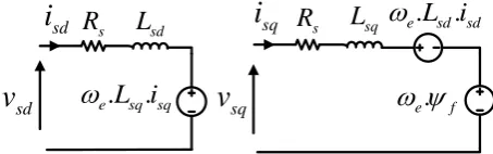
It can be concluded from Eq. (12) that the electromagnetic torque and hence, the rotational speed, can be controlled through adjusting the q-axis component of the stator current. The equivalent circuits of PMSG in the d and q axes are depicted in Fig. 3.
Table 1 Values of the coefficients in CP equations.
Coefficient Value
k1 0.5176
k2 116
k3 0.4
k4 0.5
k5 21
k6 0.0068
Fig. 2 Power coefficient curves for different values of pitch angle.
3 Proposed MPPT Algorithm
The proposed MPPT algorithm has three operational modes, which are selected based on the variations of the wind speed. These modes are designed in a way to be comprehensive and different possible conditions of wind speed variations have been anticipated and considered in this algorithm. If the wind speed is constant or has smooth variations in a time period, the algorithm will operate in the first or the second mode. Otherwise, the third mode would be selected. The following criterion has been used to determine the right operational mode in which the algorithm should work.
w
dV d
dt (13)
where d is a positive constant. There is no specific calculation method for this parameter, but it is not difficult to choose a reasonable value for it. The value of this parameter is used as a criterion for the algorithm to decide when to consider the variations of the wind speed as smooth or as intense, and accordingly decide to switch between the corresponding modes. If Eq. (13) is satisfied, the proposed algorithm operates in the first or second mode. Otherwise, it will work in the third mode.
3.1 Mode 1
In the first mode, the rotational speed reference is initially set to the value obtained from the following equation by considering the optimal value of tip speed ratio.
0
opt w ref
V
R
(14)
where Vw is the measured wind speed. However, it should be noted that the wind speed does not have the same value in different points around the swept area of the blades and it is measured using anemometers installed in some points on top of the nacelle. These measured values are the wind speed at those specific points and cannot represent the effective wind speed. Therefore, wind speed measurement does not have satisfactory accuracy. Accordingly, the initial speed reference in Eq. (14) is not precisely the optimal point, because of the inaccuracy of the wind speed measurement. Hence, this point is called the pseudo-optimum operational point in this work, since it is close to the optimal point, but not exactly the same.
s
R
L
sq
e.
L i
sd.
sd.
e f
s
R
L
sd.
.
e
L i
sq sq
v
sqsd
v
sd
i
i
sqFig. 3 Equivalent circuits of PMSG in d and q-axis.
Iranian Journal of Electrical & Electronic Engineering, Vol. 14, No. 1, March 2018 41 After setting the operating point to the
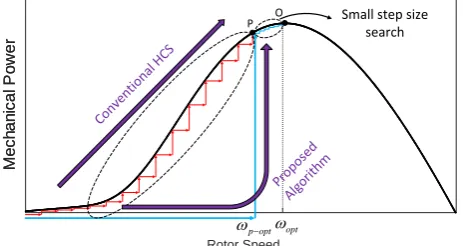
pseudo-optimum value, an HCS search with a small step size is employed to bring this point to the exact optimal point corresponding to the MPP. The principle of this mode is depicted in Fig. 4 where the points P and O represent the pseudo-optimum and the exact optimum points, respectively. By utilizing this strategy, the HCS search needs much less time to track the MPP, and also the computational burden is significantly reduced compared to the classical HCS method. This is because of the fact that the algorithm begins the searching procedure from an initial point very close to the MPP. This algorithm has a high tracking speed, and the searching step size can be chosen very small to reduce the oscillations around the MPP and achieve high accuracy as well. Therefore, the proposed MPPT strategy will have great tracking speed and accuracy.
3.2 Mode 2
This mode is basically designed to operate as an intermediate stage between the modes 1 and 3. The main purpose of this mode is to calculate an optimal coefficient which is used in the third mode. This coefficient relates the rotor speed and the mechanical power. Combining equations (1), (4) and (5) yields the following expression for the turbine mechanical power.
3 5 3 1 2 m m P
P C R
(15)
Assuming that the system is running at MPP, the CP and
λ in Eq. (15) should be replaced with their optimal values i.e.
max
p
C and λopt, respectively. Therefore,
Eq. (15) can be rewritten as the following form.
3
m opt m
P K (16)
max 5 3 1 1 2 opt p opt
K C R
(17)
The Kopt value will change as the system ages, and according to Eq. (17), it is also dependent on the air density. As mentioned earlier, the main purpose of this mode is to calculate the optimum value of the
Rotor Speed opt p opt M e c h a n ic a l P o w e r M e c h a n ic a l P o w e r Conv entio
nal H CS
Prop osed
Algo rithm
Small step size search
P O
Fig. 4 Principle of the first mode of the proposed MPPT algorithm.
coefficient Kopt for using in the third mode. For this purpose, when the wind speed is constant, even in a very small time period, and also the MPP is reached, the algorithm will switch to the second mode. In this mode, the reference speed will be fixed to the detected optimal value and then Kopt will be calculated and stored (updated) using Eq. (16) and values of Pm and ωm at the MPP.
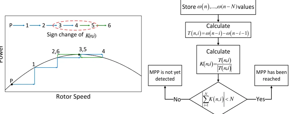
In this mode, the lock-on mechanism is adapted and used as an efficient check to ensure that the MPP is detected. This mechanism uses the direction of the rotor speed perturbations in the current and several previous time intervals to find out whether the search algorithm has detected the MPP or not. To this end, the algorithm calculates the difference between the successive rotor speed values as given in Eq. (18) where N is the total number of time intervals that are considered in the calculations. The values of T(n,i) are then normalized as expressed in Eq. (19) to represent the direction of the corresponding perturbations.
,
1
0,1, ,T n i n i n i i N (18)
,
, , T n i K n iT n i
(19)
The main idea of this detection mechanism is that if the perturbations in previous intervals until the current point are all in the same direction, it can be deduced that the algorithm is still searching and it has not yet reached the MPP. Consequently, if the lock-on mechanism detects at least one change in perturbation direction of the rotor speed over N successive time intervals, it means that the search algorithm has reached the MPP as depicted in Fig. 5. In this figure, the algorithm begins the search from point P which is the pseudo-optimum point to reach the MPP. As can be seen in this figure, the algorithm continues the search in the same direction until it reaches point 4 where detects that the MPP has been crossed and will reverse the direction of the next perturbation. Accordingly, the condition to detect the MPP can be expressed as Eq. (20). If there are any changes in the perturbation directions, it means that the MPP has been detected and the expression in this equation returns a value lower than N in this case. Otherwise, it returns the exact value of N which means that the MPP is yet to be located. The flowchart of the proposed lock-on mechanism is shown in Fig. 6.
1 ,
N
i
K n i N
(20)By utilizing this strategy, the Kopt in this algorithm will be adaptive regarding the changes in the air density and also regarding the system aging, because it is continually updated. Moreover, fixing the speed reference in this mode also eliminates the little oscillations of the operating point around the maximum
Iranian Journal of Electrical & Electronic Engineering, Vol. 14, No. 1, March 2018 42 point and the MPPT efficiency will be even more
improved for constant wind speeds. The algorithm remains in this mode until the wind speed changes.
3.3 Mode 3
The first two modes are activated when the wind speed is constant or has smooth variations. When the wind speed has turbulent variations over a time period, the first mode will not be precise and fast enough for determining the optimal speed reference. This is due to the fact that the pseudo-optimum point is changing rapidly in this condition and there may not be enough time for the P&O search in the mode 1 to bring the pseudo-optimum point to the exact MPP. Therefore, if this condition is detected through the check in Eq. (13), the algorithm switches to the third mode. Considering that this mode has a completely different principle from the first mode and is not based on the P&O search, it is able to track the optimal point with significant speed and accuracy under rapid wind variations.
In this mode, by having the stored Kopt from mode 2, the reference speed is determined from Eq. (21), which is the rewritten form of the optimum power-speed equation in Eq. (16). It should be reminded that the Kopt
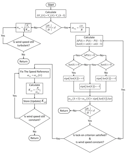
value is continually updated in mode 2 and is adaptive regarding the changes in air density. Therefore, this algorithm has great speed and accuracy in all the possible conditions of wind speed variation. Finally, the overall flowchart of the proposed method is depicted in Fig. 7.
3 _
m ref
opt updated
P K
(21)
4 Simulation Results and Discussion
For investigating the performance of the proposed MPPT method, a small-scale WECS is modeled and
simulated using MATLAB/Simulink software package. The simulated system parameters are given in Table 2. As the first scenario, the wind speed is assumed to have step changes. The conventional MPPT methods including TSR, PSF, OTC and P&O and also the proposed method are simulated for the studied WECS. The variations of the wind speed have a profound effect on the performance of the MPPT method. Most of the MPPT methods present good performance when the wind speed is constant or has smooth variations. However, their performance will deteriorate when the wind speed has intensive variations. Therefore, in order to verify the appropriate performance of the proposed algorithm in such conditions, the studied system is also simulated for another wind speed profile with intensive variations. The simulation results will be discussed and compared in this section.
4.1 Case I: Wind Speed with Step Changes
In this case, the wind speed is assumed to be fixed at 10m/s, which increases at t = 1s by a step change to 12m/s and then decreases to 11m/s at t = 2s. The mechanical power waveforms are shown in Fig. 8. For better comparison of the transient-state performances around t = 1s and t = 2s, this figure is magnified at these two points and is shown in Fig. 9 and Fig. 10, respectively. As seen from these figures, the proposed algorithm has the fastest dynamic response compared to the conventional methods. Moreover, it has also the greatest value of steady-state mechanical power. The rotor speed waveforms are depicted in Fig. 11. This figure is also magnified around t = 1s and t = 2s and shown in Fig. 12 and Fig. 13, respectively. These figures also approve the superiority of the proposed algorithm in terms of having the fastest dynamic response. In the same way, the tip speed ratio and the power coefficient waveforms are shown in Figs. 14-16 and Figs. 17-19, respectively.
1
P
2,6 3,5 4
1
P 2 3 4 5 6
Sign change of K ni( , )
Rotor Speed
P
ow
er
Calculate
Store values
MPP is not yet detected
MPP has been reached
Yes
,
1
T n i n i n i
Calculate
, ,, T n i K n i
T n i
1,
N
i
K n i N
No
n ,..., ( n N)
Fig. 5 Principle of the lock-on mechanism to detect MPP. Fig. 6 Flowchart of the lock-on mechanism.
Iranian Journal of Electrical & Electronic Engineering, Vol. 14, No. 1, March 2018 43 It is obvious from Figs. 17-19 that the proposed
method has the greatest values of steady state power coefficient, and therefore, harvests the greatest amount of energy. The transient response times, and the extracted energies during the simulation time period are given for the proposed MPPT algorithm and the conventional methods in Table 3. For better demonstration of advantages of the proposed algorithm, the transient response times are depicted and compared in Figs. 20-21. It is obvious that the proposed algorithm has much faster response compared to the conventional
methods. The extracted energies of the studied methods are also compared in Fig. 22. The numeric range of the vertical axis in this figure has been chosen in such a way that the difference between the results could be seen clearly. As expected from the waveforms of the mechanical power and power coefficient, the proposed MPPT algorithm has extracted the greatest amount of energy from the wind. The harvested energy by the proposed algorithm has increased comparing to the other simulated methods between 3.243% (in relation to OTC) and 5.518% (in relation to HCS).
Start
Calculate
-
-1
w w w
V k V k V k
3 m
ref opt
P K
dVw
d dt
Fix The Speed Reference
ref ref k
Calculate
3
m opt
ref
P K
Store (Update)
K
optCalculate
( ) ( ) ( 1)
P k P k P k
( )k ( )k (k 1)
( ) 0
P k
( )k 0
1sign k
1sign k sign
k
1
1
.ref k ref k sign k
0
. w ref
V R
( )k 0
No Yes
Yes
No Yes
Yes No
Is lock-on criterion satisfied? &
Is wind speed constant? Is wind speed still
constant?
Return No Is wind speed still
turbulant?
Return No
Yes Yes
Yes
Yes
w
dV d dt
Return
Fig. 7 Block diagram of the proposed MPPT algorithm.
Iranian Journal of Electrical & Electronic Engineering, Vol. 14, No. 1, March 2018 44
Table 2 System parameters.
PMSG Nominal Power 3.9 kW
Maximum Extracted Power at the Base
Wind Speed (12 m/s) 2630 W
Stator Resistance (Rs) 0.18 Ω
Stator Inductance (Ld = Lq) 1.67 mH
Permanent Magnet Flux 0.0714394 V.s
Number of Pole Pairs 4
Total Inertia 0.000621417 kg.m2
PWM Switching Frequency 1260 Hz
Fig. 8 Mechanical power.
Fig. 9 Mechanical power (zoomed after the first step).
Fig. 10 Mechanical Power (zoomed after the second step).
Fig. 11 Rotor speed.
Fig. 12 Rotor speed (zoomed after the first step).
Fig. 13 Rotor speed (zoomed after the second step).
Fig. 14 Tip speed ratio.
Fig. 15 Tip speed ratio (zoomed after the first step).
Fig. 16 Tip speed ratio (zoomed after the second step).
Iranian Journal of Electrical & Electronic Engineering, Vol. 14, No. 1, March 2018 45
Fig. 17 Power coefficient.
Fig. 18 Power coefficient (zoomed after the first step).
Fig. 19 Power coefficient (zoomed after the second step).
Fig. 20 Transient response times for case 1 (after t = 0).
Fig. 21 Transient response times for case 1 (after t = 1s and t
= 2s).
Fig. 22 Extracted energy for the studied MPPT methods in case 1.
Table 3 Comparison between the MPPT methods (wind speed profile with step changes).
Method Proposed TSR PSF OTC HCS
Response Time After t = 0 (sec) 0.1 0.6 0.24 0.88 0.72
Response Time After t = 1 (sec) 0.0036 0.0066 0.074 0.028 0.098
Response Time After t = 2 (sec) 0.002 0.005 0.089 0.014 0.049
Extracted Energy (j) 5316 5061 5117 5149 5038
Difference Between the Extracted Energy of the Proposed Algorithm and Other Methods (%)
5.038 3.890 3.243 5.518
Iranian Journal of Electrical & Electronic Engineering, Vol. 14, No. 1, March 2018 46 4.2 Case II: Wind Speed with Fast Variations
In this case, a wind speed profile with intensive variations is considered for investigating the performance of the proposed MPPT algorithm. The Van Hoven model is used in order to generate the wind speed profile for this case. In this model, the wind speed function consists of a mean speed value plus some oscillatory components as the following expression:
1 2
cos
N
w i i i
i
t
v t v v
(22)where v is the mean wind speed and N is the number of considered components. Moreover, vi, ωi and φi are the amplitude, angular frequency and angle of the ith
oscillatory component, respectively. The amplitudes of the oscillatory components can be calculated using the following equations:
1
1
1 2
i i i i i i
v S S
(23)
2
5 2 6 0.475
1
i
i L v S
L v
(24)
where σ is turbulence intensity and L is the turbulence length scale. The simulated wind speed profile using Van Hoven model is depicted in Fig. 23 with
v = 10 m/s.
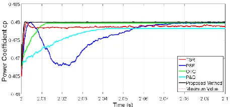
The power coefficient waveforms are compared for the proposed algorithm and the other four methods in Figs. 24-27. As it is obvious from these figures, the proposed algorithm has much better performance in realization of MPPT under the conditions with rapid wind variations. The total amounts of the extracted energy during the simulation time period (10s) for the proposed algorithm and the conventional MPPT methods are given in Table 4 and compared in Fig. 28. The numeric range of the vertical axis in Fig. 28 has been chosen in such a way that the difference between the results could be seen clearly. The proposed algorithm has extracted the greatest amount of energy. The differences between the harvested energy of the proposed algorithm and other methods are between 5.132% (in relation to TSR) and 7.371% (in relation to PSF).
Fig. 23 Wind speed profile with rapid variations.
Fig. 24 Power coefficient of the proposed algorithm and TSR method.
Fig. 25 Power coefficient of the proposed algorithm and PSF method.
Fig. 26 Power coefficient of the proposed algorithm and OTC method.
Fig. 27 Power coefficient of the proposed algorithm and P&O method.
Fig. 28 Extracted energy for the studied MPPT methods in case 2.
Iranian Journal of Electrical & Electronic Engineering, Vol. 14, No. 1, March 2018 47
Table 4 Extracted energy of the MPPT algorithms (wind speed profile with rapid variations).
Method Proposed TSR PSF OTC HCS
Extracted Energy in 10 seconds (j) 17945 17069 16713 16886 16741
Difference Between the Extracted Energy of the Proposed Algorithm and Other Methods (%)
5.132 7.371 6.271 7.192
5 Conclusion
In this article, a novel hybrid MPPT algorithm is proposed for using in WECSs. The proposed algorithm modifies the conventional methods in a way that it has their advantages and eliminates their drawbacks. The four conventional MPPT methods including TSR, PSF, OTC and P&O algorithms and also the proposed method have been compared for realization of MPPT in a small scale WECS. The studied system is simulated in MATLAB/Simulink environment using two different wind speed profiles. In the first scenario, the wind speed is constant and has only step changes. In the other case, the wind speed is assumed to have intensive variations. The simulation results verify the satisfactory performance of the proposed algorithm and its superiority over the conventional methods for both cases. The proposed method has faster transient response and is more efficient in maximizing the extracted power. The advantages of this method are even more outstanding in the second case that the wind speed has rapid variations.
References
[1] V. Nayanar, N. Kumaresan, and N. A. Gounden, “A single-sensor-based MPPT controller for wind-driven induction generators supplying DC microgrid,” IEEE Transactions on Power Electronics, Vol. 31, No. 2, pp. 1161–1172, 2016.
[2] J. C. Hui, A. Bakhshai, and P. K. Jain, “An energy management scheme with power limit capability and an adaptive maximum power point tracking for small standalone PMSG wind energy systems,”
IEEE Transactions on Power Electronics, Vol. 31, No. 7, pp. 4861–4875, 2016.
[3] V. Yaramasu, B. Wu, S. Alepuz, and S. Kouro, “Predictive control for low-voltage ride-through enhancement of three-level-boost and NPC-converter-based PMSG wind turbine,” IEEE Transactions on Industrial Electronics, Vol. 61, No. 12, pp. 6832–6843, 2014.
[4] A. Darijani, A. Kiyoumarsi, B. M. Dehkordi, H. Lari, S. Bekhrad, and S. Rahimi, “Design of a Permanent-Magnet Synchronous Generator for a 2 MW Gearless Horizontal-Axis Wind Turbine According to its Capability Curve,” Iranian Journal of Electrical & Electronic Engineering (IJEEE), Vol. 11, No. 1, pp. 52–60, 2015.
[5] K. Sayed and M. Abdel-Salam, “Dynamic performance of wind turbine conversion system using PMSG-based wind simulator,” Electrical Engineering, Vol. 99, No. 1, pp. 431–439, 2017.
[6] D. Kumar and K. Chatterjee, “A review of conventional and advanced MPPT algorithms for wind energy systems,” Renewable and Sustainable Energy Reviews, Vol. 55, pp. 957–970, 2016.
[7] M. A. Abdullah, A. Yatim, C. Tan, and R. Saidur, “A review of maximum power point tracking algorithms for wind energy systems,” Renewable and sustainable energy reviews, Vol. 16, No. 5, pp. 3220–3227, 2012.
[8] M. Nasiri, J. Milimonfared, and S. Fathi, “Modeling, analysis and comparison of TSR and OTC methods for MPPT and power smoothing in permanent magnet synchronous generator-based wind turbines,” Energy Conversion and Management, Vol. 86, pp. 892–900, 2014.
[9] D. Y. Li, Y. D. Song, Z. X. Gan, and W. C. Cai, “Fault-tolerant optimal tip-speed-ratio tracking control of wind turbines subject to actuation failures,” IEEE Transactions on Industrial Electronics, Vol. 62, No. 12, pp. 7513–7523, 2015.
[10]Y. Zhao, C. Wei, Z. Zhang, and W. Qiao, “A review on position/speed sensorless control for permanent-magnet synchronous machine-based wind energy conversion systems,” IEEE Journal of Emerging and Selected Topics in Power Electronics, Vol. 1, No. 4, pp. 203–216, 2013.
[11]R. Aubrée, F. Auger, M. Macé, and L. Loron, “Design of an efficient small wind-energy conversion system with an adaptive sensorless MPPT strategy,” Renewable Energy, Vol. 86, pp. 280–291, 2016.
[12]L. C. Pagnini, M. Burlando, and M. P. Repetto, “Experimental power curve of small-size wind turbines in turbulent urban environment,” Applied Energy, Vol. 154, pp. 112–121, 2015.
[13]M. N. Uddin and N. Patel, “Maximum power point tracking control of IPMSG incorporating loss minimization and speed sensorless schemes for wind energy system,” IEEE Transactions on Industry Applications, Vol. 52, No. 2, pp. 1902– 1912, 2016.
Iranian Journal of Electrical & Electronic Engineering, Vol. 14, No. 1, March 2018 48 [14]M. Kesraoui, N. Korichi, and A. Belkadi,
“Maximum power point tracker of wind energy conversion system,” Renewable Energy, Vol. 36, No. 10, pp. 2655–2662, 2011.
[15]S. M. R. Kazmi, H. Goto, H.-J. Guo, and O. Ichinokura, “A novel algorithm for fast and efficient speed-sensorless maximum power point tracking in wind energy conversion systems,” IEEE Transactions on Industrial Electronics, Vol. 58, No. 1, pp. 29–36, 2011.
[16]X. Du and H. Yin, “MPPT control strategy of DFIG-based wind turbines using double steps hill climb searching algorithm,” in 5th International Conference on Electric Utility Deregulation and Restructuring and Power Technologies (DRPT), pp. 1910–1914. 2015.
[17]R. M. Linus and P. Damodharan, “Wind Velocity Sensorless Maximum Power Point Tracking Algorithm in Grid-connected Wind Energy Conversion System,” Electric Power Components and Systems, Vol. 43, No. 15, pp. 1761–1770, 2015.
[18]A. H. Rajaei, M. Mohamadian, S. M. Dehghan, and A. Yazdian, “PMSG‐based variable speed wind energy conversion system using Vienna rectifier,”
International Transactions on Electrical Energy Systems, Vol. 21, No. 1, pp. 954–972, 2011.
[19]J. Lee and Y.-S. Kim, “Sensorless fuzzy-logic-based maximum power point tracking control for a small-scale wind power generation systems with a switched-mode rectifier,” IET Renewable Power Generation, Vol. 10, No. 2, pp. 194–202, 2016.
[20]X. X. Yin, Y. G. Lin, W. Li, H. W. Liu, and Y. J. Gu, “Fuzzy-logic sliding-mode control strategy for extracting maximum wind power,”
IEEE Transactions on Energy Conversion, Vol. 30, No. 4, pp. 1267–1278, 2015.
[21]A. Medjber, A. Guessoum, H. Belmili, and A. Mellit, “New neural network and fuzzy logic controllers to monitor maximum power for wind energy conversion system,” Energy, Vol. 106, pp. 137–146, 2016.
[22]C. Wei, Z. Zhang, W. Qiao, and L. Qu, “An adaptive network-based reinforcement learning method for MPPT control of PMSG wind energy conversion systems,” IEEE Transactions on Power Electronics, Vol. 31, No. 11, pp. 7837–7848, 2016.
[23]J. Mérida, L. T. Aguilar, and J. Dávila, “Analysis and synthesis of sliding mode control for large scale variable speed wind turbine for power optimization,” Renewable Energy, Vol. 71, pp. 715–728, 2014.
[24]S. Chichester, Grid integration of wind energy conversion systems. Wiley, 385p, 1999.
[25]S. Li, T. A. Haskew, and L. Xu, “Conventional and novel control designs for direct driven PMSG wind turbines,” Electric Power Systems Research, Vol. 80, No. 3, pp. 328–338, 2010.
S. Heshmatian was born in Tehran, Iran, in 1992. He received the B.Sc. and M.Sc. degrees in Electrical Engineering from
Iran University of Science and
Technology (IUST), Tehran, Iran, in 2014 and 2016, respectively. His research
interests include power electronic
converter topologies and control
strategies and renewable energy systems.
D. Arab Khaburi was born in 1965. He
has received B.Sc. in Electronic
Engineering, in 1990 from Sharif
University of Technology, Tehran, Iran, and M.Sc. and Ph.D. in Electrical Engineering, from ENSEM, INPEL, Nancy, France in 1994 and 1998, respectively. Since January of 2000 he has been as a faculty member in Electrical Engineering Department of Iran University of Science Technology (IUST), where he is currently as an Associate Professor. He is also a member of Center Of Excellence for Power Systems Automation and Operation. His research interests are Power Electronics, Motor Drives and Digital Control.
M. Khosravi was born in Tehran, Iran, in 1993. He received the B.Sc. and M.Sc. degrees in Electrical Engineering from
Iran University of Science and
Technology (IUST), Tehran, Iran, in 2014 and 2016, respectively. He is currently pursuing the Ph.D. degree in Electrical Engineering at Iran University of Science and Technology (IUST). He is also a member of Iran’s National Elites Foundation. His research interests include power electronic converter topologies and control strategies, renewable energy systems and electrical drives.
A. Kazemi Received the M.S. degree in Electrical Engineering from Oklahoma State University, Stillwater, Ok, USA, in 1979. Currently, he is an Associate Professor and Power Systems’ Research Group Coordinator with the Electrical Engineering Department, Iran University of Science and Technology, Tehran, Iran. His research interests are reactive power control and planning as well as power system dynamics, stability, and control.