Open-Source
UML Modeling
Learn to use the NetBeans UML Modeling Project
by reverse engineering a complete Java application
Open-Source
UML Modeling
T
he UML Modeling Project(uml.netbeans.org), which
started as a part of the Enterprise Pack is now a separate download provid-ing full UML support in NetBeans IDE. This article showcases NetBeans’ UML sup-port, going through a case study where we reverse engineer a working Java ap-plication, highlighting the IDE’s modeling features in the process.
UML and the Java developer
If you are an Agile Modeling advocate like me, your first thought might be “why should I care about UML support in a Java IDE?” Today, leading software engineer authors and even UML early adopters like Martin Fowler and Scott Ambler stand by “modeling on a napkin”: using models only as sketches before building the “real soft-ware” (i.e. the source code). Indeed some developers today dismiss modeling as un-necessary and bureaucratic.However, UML modeling will be useful at some point to most Java developers, whether they’re involved in enterprise, desktop or mobile projects. Modeling has its role even in radical XP development, as no significant piece of software can be built with a minimum level of quality with-out some planning and design. “Traveling light” doesn’t mean you should not model at all, but that you should do all the model-ing that adds value to your project.
Not all Java developers are Agile Model-ing converts though. Many prefer to em-brace the MDA paradigm, at the other end of the modeling spectrum. In Model-Driven Architecture the idea is that your models will generate most if not all source code,
and MDA tools like AndroMDA (andromda.org) have been quite suc-cessful in the Java arena. MDA advocates will be happy to find that the NetBeans UML modules provide many features absent from other open-source CASE tools, and even come with an extensible Design Pattern Catalog, including not only classical GoF patterns but also many Java EE Blueprints out-of-the-box.
Installing NetBeans UML Modeling
UML Modeling is available as a feature from the NetBeans Update
Center (accessible through the IDE’s
Tools menu). At the time of
writing, you had to check the
NetBeans Update Center Beta (see
Figure 1) to download it, but readers will probably find the UML
Modeling Project on the stable
NetBeans Update Center when this
edition is out.
In NetBeans, select UML Modeling in the
Features category and
click Add (Figure 2). You’ll see there are many modules to install
Figure 2.
Selecting the
UML Modeling
feature
A
2
A
Figure 1.
Selecting the
Update Center
for modules
still in beta
A
1
A
uml.netbeans.org
UML Modeling
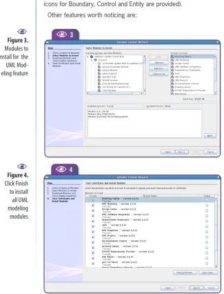
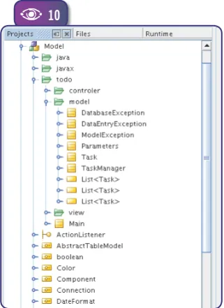
(Figure 3). After you agree to a few licenses, NetBeans starts downloading. When the downloads are done, click Finish to install
the modules (see Figure 4). (If you are not the only user of your
development workstation, be sure to check the
Global option for
all modules.) Finally, after restarting NetBeans you’ll find new UML project templates and configuration options in the IDE.
UML features overview
The NetBeans UML Modeling Project supports ten standard UML diagrams: Use Case, Class, Collaboration, Sequence, Activity, State, Component, Deployment, Object and Robustness.
Even though they’re not displayed in the New Diagram wizard,
Object diagrams can be built as a Collaboration diagram, and Robustness diagrams as Class diagrams (the standard stereotype icons for Boundary, Control and Entity are provided).
Other features worth noticing are:
Java code generation – Java pack-ages, classes and interfaces can be gen-erated directly from the UML model;
Round-trip engineering – if a UML project is linked to a Java project, chang-es in code are automatically reflected in the model;
Ability to nest diagrams and pack-ages inside other model elements;
A Design Center, which provides an extensible design pattern catalog;
Rich-text documentation for model elements created directly inside the IDE;
Operations and attributes can be shown in class elements using either standard UML notation or Java syntax;
Generation of model reports in Java-Doc format.
The Case Study
We’ll use the reverse engineering of an ex-isting desktop application as a case study for exploring NetBeans’ UML features. Dur-ing the process, we also show hints that are useful for forward-engineering projects (from model to source). Readers are not expected to be proficient in UML modeling to follow this tutorial, but basic modeling knowledge will be helpful.
The application used for the case study was created for NetBeans Magazine Issue One. It’s a simple Task Manager, similar to those provided in a PIM suite. The “Todo”
applica-tion has two windows: a task list (Figure 5)
and a task editing form (Figure 6). The task
list window displays tasks ordered either by priority or by due date, and it can filter out completed tasks. Tasks are colored to indicate completed, late or alert status. The complete application is available as a down-load in the NetBeans Magazine’s website.
[image:3.581.45.371.293.720.2]
Figure 3.
Modules to
install for the
UML
Mod-eling feature
A
3
A
Figure 4.
Click Finish
to install
all UML
modeling
modules
A
4
A
uml.org
The Unified P
rocess Explained,
Kendall Scott
How to use
UML as part
of a
tradition-al software
development
process
Our application is quite simple, so re-verse engineering it won’t be a complex task. Even so, it is complex enough for us to demonstrate many of NetBeans’ UML features. We’ll work through the ap-plication as if we didn’t know how it was designed, using UML diagrams to under-stand its structure and design ideas.
Creating the
reverse-engineering
project
Installing the UML modeling project adds a new project category to NetBeans, with
three project templates (Figure 7).
Platform-Independent
Model projects use
standard UML notation for class attributes and operations, and do no code genera-tion. This template is useful in the initial stages of the development process, when all models are “conceptual” and not “phys-ical”.Java-Platform
Model projects use Java
syntax for class attributes and operations and must be linked to a Java Application or Library project. NetBeans will keep both projects in sync: If you edit the code, the UML model will change to reflect new or changed classes, attributes and opera-tions, and if you change the UML model, the source code will be modified accord-ingly.We’ll use the third project template, which populates a Java-Platform Model from an existing Java project. Click the
New Project icon and choose the UML
cat-egory. Then select Java-Platform Model byReverse Engineering a Java Project. Accept
the defaults for the next step, except for selecting the Todo Java project; then clickFinish (see
Figure 8). NetBeans will scanthe sources and populate the project with model elements for Java packages, classes and interfaces. (Note that for large projects this may take a long time and eat up a large amount of memory.)
If you experience
OutOfMemory
errors while reverse engineering, you can
edit the file
etc/netbeans.conf
inside your NetBeans installation and change
the value for
–Xmx,
increasing the maximum heap size from 128M to 256M or
bigger.
While scanning, the IDE shows a log window detailing the prog-ress for each source file. When the scanning finishes, click Done to dismiss this window, and you’ll end up with a new UML project as
shown in Figure 9.
Anatomy of a UML Project
A UML project is organized into three containers: Model, Diagrams and Imported Elements.
The
Model container holds all elements created as part of the
model. Elements can be Classes, Interfaces, Packages, Actors,E
Figure 6.
The task form
window
A
Figure 5.
The task list
window
A
6
A
5
UML Modeling
Diagrams, Notes, Data Types, As-sociations and anything else that can be defined as part of the UML project itself.
The
Diagrams container provides
quick access to all diagrams created as part of the model. You may be surprised to see there are no diagrams in our reverse-engineering project. That’s because a UML model consists of model elements, which may or may not be shown as diagrams. Every UML diagram is a partial view of a model, and you’ll need to choose which details to show and which to leave out. So NetBeans populates the reverse-engineered model with ele-ments but leaves the diagram creation to the developer.Finally, the
Imported Elements
container allows a model torefer-ence elements created as part of another model (i.e. another UML Project). This is useful for organizing large models as a set of UML projects; for example one for business logic and another for GUI elements. It’s also useful for reusing model elements in various proj-ects. And it allows for a Platform-independent UML Model that’s referenced by a Java Platform UML Model. This way, you can start
with conceptual modeling and then move on to physical modeling, and keep track of which physical elements realize which
conceptual elements1.
Exploring the
reverse-engineered model
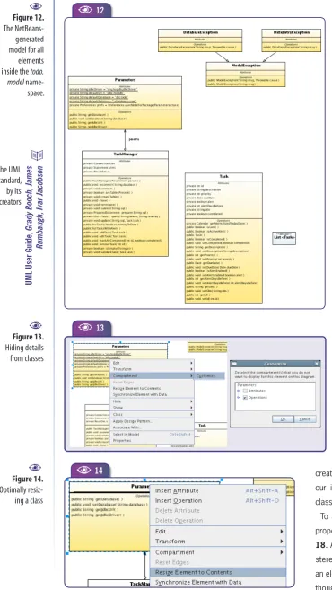
Expand the Model container and you’ll see that it includes both application-specific and standard Java packages and classes (Figure 10). As a UML model cannot ref-erence anything it does not contain or im-port, NetBeans creates model elements for Java SE classes. (An alternative would be having a UML model with the Java SE API and import elements from it.)
Sometimes NetBeans will create
dupli-cates, like the many
List<Task>
elementsyou see in Figure 10. It’s better to leave
them as they are, as removing them may delete attributes from the Java project.
Generating a class
diagram
The Todo application has only a few
classes, all of which are inside the
todo
package and its subpackages. It would be possible to create a “complete” Class Dia-gram, but for most real-world applications the resulting diagram would be very hard to read and therefore mostly useless. It’s usually better to start by creating a class diagram for each package, and then check the dependencies between packages or between a few important classes.
Let’s start with the
todo.model
package.Select all its elements, right click on the selection and choose Create Diagram from Selected Elements from the context menu. Then choose Class Diagram in the wizard
(see Figure 11).
Figure 7.
UML project
templates
A
9
A
Figure 8.
Creating a
UML Project
for
reverse-
engineer-ing a Java
Project
A
A
87
A
1A «realize» UML
relationship between two model elements states that one ele-ment represents an abstract concept in the problem domain, while the related element represents a software construct implementing that concept, making it “physical” in the soft-ware’s point of view.
F
Figure 9.
The new UML
project
Note that the “Namespace” combobox lists what seem to be all the packages in the current model. In fact, every UML package (and most other UML elements)
corresponds to a UML Namespace. You
can use namespaces for any kind of mod-el mod-element. Leaving the class diagram for the
todo.model
package inside thetodo::
model
namespace makes the diagram easier to find. It also makes it clear that the diagram refers to elements of that package.The resulting diagram is shown in
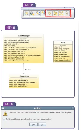
Figure 12. Note that NetBeans is pretty smart in laying out its elements. But even with an optimized layout and a small set of classes, the generated diagram is quite large. The fact is there’s too much detail, especially if we just want to understand the relationships between elements in the package. Fortunately you can hide most of the excess information.
A good start is hiding all private fields and
methods (Figure 13). Right-click on each
class and select Compartment>Customize,
then uncheck the entire “Attributes”
com-partment or expand it to select specific fields to hide. After hiding
an element’s details, you can right-click Resize Element to
Con-tents to optimally resize it (Figure 14). (You can also hide/show a compartment by double-clicking the compartment separators.)
After these changes, the diagram will probably need some rear-rangement. NetBeans can do this using four different auto-layouts, accessible through the last four buttons in the Diagram Editor
tool-bar (see Figure 15). Click the first button, for Hierarchical Layout.
This is the default layout NetBeans uses when generating a
dia-gram from model elements. The results are shown in Figure 16.
Inferring meaning from
a generated diagram
Notice I deleted the
List<Task>
element from the diagram, aswell as all exception classes. When deleting an element, NetBeans gives you the choice of removing it from the diagram only, or from
the diagram and the model (see Figure 17).
[image:6.581.30.191.64.285.2]I’ve shown only public methods for
Parameters
andTaskManager
,Figure 10.
The new UML
project, showing
a few model
elements
A
10
A
11
[image:6.581.210.474.360.718.2]A
Figure 11.
Creating a
class diagram
from model
elements
A
martinfowler
.com/articles.html
objectmentor
.com/resources/publishedArticles.html thoughtworks.com/byline
-articles.html
UML Modeling
and only attributes (all private) for the
Task
class. That’s because Ias-sume
Task
is a DTO (Data TransferObect) or Value Object, and show-ing accessor methods wouldn’t help in understanding the class. But for
Parameters
the attributes do not map exactly to the getters, so I assume the class has some intelligence ofits own. I also assume
TaskManager
is a DAO class, and that it uses
Pa-rameters
to get JDBC connection parameters.As you can see, reverse-engineer-ing a model from Java code involves a lot of assumptions and common sense. You’ll always be making edu-cated guesses about the role played by each element in the application, and using these decisions to create your diagrams to best effect.
Enhancing the
generated model
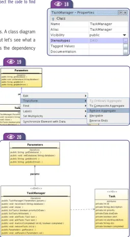
Based on the reverse engineering done so far, we have identified the use of common design patterns in the ap-plication. UML provides a nice feature to make these explicit in a model: ste-reotypes2. A few standard stereotypes
are defined in the UML standard, and you can create new ones freely. We’ll create the «VO» and «DTO» stereotypes so our interpretation of the purpose of each class is explicit in the model.
To add a stereotype to a class, use the
properties window, as shown in Figure
18. An editor allows you to select existing
[image:7.581.37.408.59.717.2]stereotypes or create new ones. Note that an element can have many stereotypes, al-though this is not common.
Figure 12.
The
NetBeans-generated
model for all
elements
inside the
todo.
model
name-space.
A
Figure 13.
Hiding details
from classes
A
12
A
13
A
Figure 14.
Optimally
resiz-ing a class
A
A
14
UML User Guide,
Grady Booch, James
Rumbaugh, Ivar Jacobson
Now, if our conclusions are OK, the model generated by NetBeans is not entirely cor-rect. There is no part/whole relationship
between
TaskManager
andParameters
, sothey should not be connected by an ag-gregation. This should be changed to a simple association. Right-click on the ag-gregation (it should turn blue) and select Transform>Remove Aggregate from the
context menu (see Figure 19).
I fact, you should expect NetBeans (or any other UML CASE tool) to generate a few “incorrect” associations when reverse engineering Java sources. That’s because UML associations have much richer se-mantics than Java references. All struc-tural associations between Java classes originate from attributes referencing other classes/interfaces (or collections and ar-rays of these). Similarly to most other pro-gramming languages, Java does not dis-tinguish between composites, aggregates and simple associations. Also, a reference to an instance of another class could be there just for convenience, and not be a structural association at all.
Now, if
TaskManager
is a DAO class,responsible for persisting instances of
Task
, it’s clear that these two classes arestrongly coupled. Changes in
Task
fieldswill probably require changes in
TaskMan-ager
’s behavior. This can be made explicitin a UML diagram by a Dependency
re-lationship, which is available in the UML
Class Diagram Palette in the
Dependen-cies category. Click on the Dependency
tool, then on
TaskManager
in the diagramand on
Task
(also in the diagram). Thiscreates a dependency connecting the two classes. The end result is shown in
Figure 20.
Generating Dependency Diagrams
From our understanding so far, it looks like
TaskManager
is themain class of the
todo.model
package. But does our model showeverything important about this package and about
TaskManager
?NetBeans helps us check this by generating a dependency dia-gram, a type of class diagram that shows everything that’s refer-enced by a given class. Right-click a class in either the Projects window or the class diagram and select Generate Dependency Dia-gram. The diagram generated for
TaskManager
is shown in Figure21. It’s created inside the namespace defined by the class itself,
so it shows in the Projects window as a child node of the class. You can see that the only elements in the diagram that are not in our
todo.model
class diagram come from the Java SE APIs. You’dFigure 17.
By default, deleting
an element from
a diagram doesn’t
remove it from the
model
A
17
A
Figure 16.
Class diagram
for the
todo.
model
package,
after hiding
details, deleting
elements and
applying an
auto-layout
A
16
[image:8.581.211.486.53.494.2]A
Figure 15.
Auto-layout diagram
buttons from the
NetBeans diagram
editor toolbar
A
15
A
2A UML stereotype is
a label you can add to elements to highlight specific semantics. You can think of a ster-eotype as a subclass or role of a kind of model element.
UML Modeling
get similar results with other classes from the same package, so it’s safe to assume the class diagram built for the package has enough information.
The dependency diagram for
TaskManager
is an example of a“dis-posable diagram”. There’s no value in keeping it around after using it to verify that other related diagrams have enough information. You should delete the diagram from the model, and also the dependency diagrams for other classes in the same package (if you generated them). The key is not to pollute your model with useless diagrams.
NetBeans-generated dependency diagrams don’t take into account classes
referenced inside a method body. Only attribute and method declarations are
followed, so there will be cases when you’ll need to inspect the code to find
additional dependencies and add them manually.
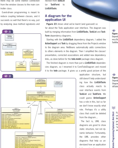
The todo.controller package
The
todo.controller
package has only two classes. A class diagram for this simple package would be of little use, but let’s see what adependency diagram tells us. Figure 22 shows the dependency
diagram for the
ListEditTask
class, already“simplified” as we did with the
todo.model
package class diagram.
Here we see many classes coming from different packages. Either we have found a crucial class for the application, or the ap-plication design is a mess. Method signatures may help us understand how these classes
are related to each other. They suggest
ListE-ditTasks
is an event listener for bothTaskList
andTaskForm
. It looks likeListEditTasks
reactsto those events by calling
TaskManager
meth-ods, acting as a workflow controller for the application.
Note also that
TaskList
andTaskForm
are thetwo windows in the application. The fact that
both are connected to
ListEditTasks
stronglysuggests it’s the main controller class for the application.
The dependency diagram for
CreateOpenTaskList
shows connections toTaskList
andTaskManager
, similar to the onesfrom
ListEditTasks
. It seemsCreateOpenTaskList
E
is the controller for some secondary usage
scenarios, so we should examine
ListEdit-Tasks
the same way we did withTaskMan-ager
.If we have found the main controller class, the dependency diagrams for the window classes should not add much new information. Surprisingly, the dependency
diagrams for
TaskList
andTaskForm
do notshow any connection with
ListEditTasks
. Butthey do show a new connection with
Action-Figure 20.
Class diagram model
for the
todo.
modelpackage after
chang-ing associations
between elements.
Note the dependency
from
TaskManagerto
Task, and that the
association from
TaskManager
to
Parameter
is no
longer an
aggrega-tion. Note also the
stereotypes for
Task-Managerand
Task.
A
Figure 19.
Transforming
an aggregation
into a simple
association
A
19
[image:9.581.297.553.253.716.2]A
Figure 18.
Adding a
stereotype to
a class
A
A
18
20
Support
, which is a SwingActionListener
.ListEditTasks
is also anActionListener
, so there may be some indirect connection from the window classes to the main con-troller class.Event-driven programming is meant to reduce coupling between classes, and it succeeds so well that there’s no way, just by analyzing Java method signatures and
attribute declara-tions, to find a
con-nection from
TaskList
(or
TaskForm
) toListEditTasks
. [image:10.581.26.512.104.713.2]A diagram for the
application UI
Figure 23 shows what we’ve learnt (and guessed) so
far about the Todo application user interface. The diagram was
built by merging information from
ListEditTasks
,TaskList
andTask-Form
dependency diagrams.Starting with the
ListEditTask
dependency diagram, I added theActionSupport
andTask
by dragging these from the Projects window to the diagram area. NetBeans automatically adds connections to others elements in the diagram. Then I simplified the classes’ presentation, corrected associations and added new dependencylinks, as done before for the
todo.model
package class diagram.The finished diagram is more than just a
ListEditTask
dependen-cies diagram, so I renamed it to CoreTodoDiagram and moved
it to the
todo
package. It gives us a pretty good picture of theapplication structure, but still doesn’t help
understand-ing how the
ListEditTasks
class actually reacts to user interface events from
TaskList
andTaskForm
. Wecould guess
ActionSupport
has a role in this, but so far we don’t know exactly what role. Perhaps it’s a utility class that could be deleted from the diagram…
The fact is, UML class diagrams are good to show static structure, but not dy-namic behavior. Fortunately, the UML provides other diagrams that help us un-derstand how an application behaves at runtime.
Figure 22.
Dependency
Diagram for
ListE-ditTasks
A
22
A
Figure 21.
Depend-ency Diagram for
TaskManager
A
21
A
Extreme P
rogramming Explained,
Kent Beck
UML Modeling
23
A
Generating Sequence Diagrams
We’ve been working under the assumption that the window class-es (
TaskList
andTaskForm
) generate SwingAction
events, which aresomehow dispatched by
ListEditTasks
.ListEditTasks
should registeritself as an
ActionListener
forTaskList
, and thenTaskList
should fireAction
events toListEditTasks
.Note that
ListEditTasks
has only a constructor that receives a view(
ListTasks
) and a model (the DAO class,TaskManager
) as param-eters. Looking at the constructor code in the source Java project we can see this listener registration happening.Who calls the
ListEditTasks
constructor? The applicationmain()
method is a good candidate. Expand the
todo.Main
class node toshow the
main()
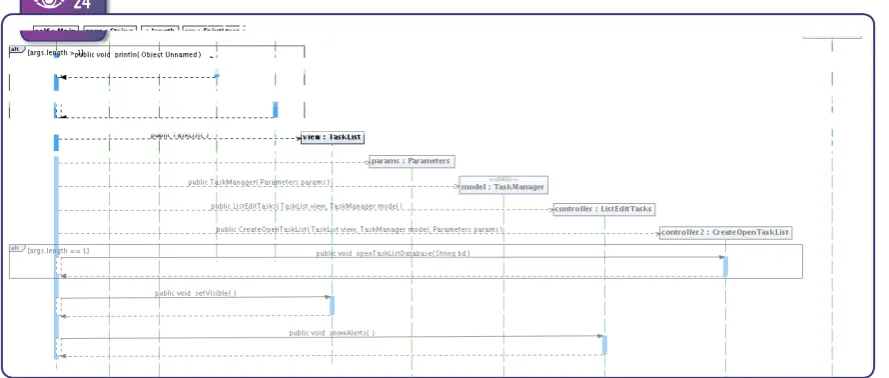
operation (UML calls “operation” what Java calls“method”), then right-click and choose Reverse-Engineer operation. In the wizard chose a Sequence Diagram and accept all defaults. The result will be a new diagram node under the operation’s node.
Figure 24 shows the diagram that NetBeans creates.
An UML sequence diagram shows the message flow among a set
of objects during the execution of an oper-ation. Note that it refers to class instances and not to the classes themselves. A solid arrow represents a message, that is, a Java method call (in UML terms, an opera-tion call). A dashed arrow is either a mes-sage return or a “create” mesmes-sage, i.e. the creation of a new object.
Again, the automatically generated dia-gram comes with too much detail.
Remov-ing the
args
,length
,err
andSystem
objects,and moving the elements around should
solve this (see the result in Figure 25).
The diagram shows that
main()
justcon-structs instances of the classes we have already identified as being the main ones for the application, and that all are
[image:11.581.84.552.69.229.2]con-nected by the
ListEditTasks
constructor. SoFigure 23.
Class diagram
for the Todo
application user
interface
A
bdn.borland.com/article/0,1410,31863,00.html
sparxsystems.com.au/UML_T
utorial.htm
far we’ve gleaned the same information we had expressed in the class diagrams. But it’s important to confirm our guesses.
The fact the
main()
operation createsno instances of other classes, and that it doesn’t call operations other than
con-structors and
setVisible()
for theTaskList
window, makes us confident of not miss-ing any important class.
Interpreting
sequence diagrams
The
main()
method sequence diagramshows connections made from
ListE-ditTasks
toTaskManager
andTaskList
(we’re ignoring the connections fromCreateOpenTaskList
toTaskList
andPa-rameters
). But the diagram doesn’t show connections going the other way, that is,from
TaskList
toListEditTasks
to dispatchAction
events. We know a view class has to send events to its controller, and that a model class has no knowledge about its controller – so there are no other missing connections.If you follow the code, you’ll see that the
ListEditTasks
constructor callsTaskList.
addActionListener()
, confirming thatListEditTasks
handlesAction
events generated by
TaskList
. This is the missing connection fromTaskList
toListEditTasks
.NetBeans won’t follow a nested class from one operation to
another. So the message
addActionListener
fromListEditTasks
toTaskList
is missing in the sequence diagram. It’s helpful to add this message manually, to get a complete picture of all connections between the Todo application main classes.NetBeans also won’t create a sequence diagram from multiple operations (as it can from multiple classes). If it could, a sequence
diagram generated from both
main()
and theListEditTasks
con-structor would show all connections that are being made. That’s understandable, as a sequence diagram following nested calls would probably be very big (how many levels down are enough?). It would also probably create a diagram where one operation “sees” the inner workings of others, violating OO encapsulation.
We still need a diagram showing event handling. We also need to
clarify the role
ActionSupport
plays in the Todo application. Againlooking at the code, we can see the window classes delegate all
Action
event dispatching to theActionSupport
class. This is done so the window classes themselves don’t have to manage multipleevent listeners. This way
TaskList
can sendAction
events to bothcontroller classes,
ListEditTasks
andCreateOpenTaskList
.By digging a little deeper into the code, we can see that each button or menu item from the window classes provides a different
actionCommand
string. The controller classes use this property to know which operation was requested by the user and then execute24
A
Figure 24.
Sequence
dia-gram generated
by NetBeans
for the
main()
operation
A
Fundamentals of
Object-Oriented
Design in UML
,
Meilir P
age
-Jones
[image:12.581.27.472.532.721.2]UML Modeling
26
A
25
A
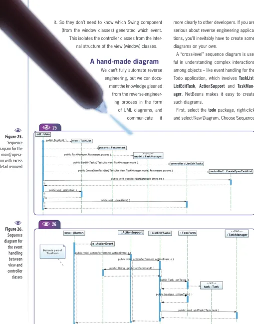
it. So they don’t need to know which Swing component (from the window classes) generated which event. This isolates the controller classes from the
inter-nal structure of the view (window) classes.
A hand-made diagram
We can’t fully automate reverse engineering, but we can
docu-ment the knowledge gleaned from the
reverse-engineer-ing process in the form of UML diagrams, and
communicate it
more clearly to other developers. If you are serious about reverse engineering applica-tions, you’ll inevitably have to create some diagrams on your own.
A “cross-level” sequence diagram is use-ful in understanding complex interactions among objects – like event handling for the
Todo application, which involves
TaskList
,ListEditTask
,ActionSupport
andTaskMan-ager
. NetBeans makes it easy to createsuch diagrams.
First, select the
todo
package, right-click [image:13.581.41.551.46.696.2]and select New Diagram. Choose Sequence
Figure 25.
Sequence
diagram for the
main()
opera-tion with excess
detail removed
A
Figure 26.
Sequence
diagram for
the event
handling
between
view and
controller
classes
Diagram, and name it ActionEventSequence. From the Projects window,
drag the elements
JButton
(javax.
swing
),ActionEvent
(java.awt.event
),Ac-tionSupport
(todo.view
),ListEditTasks
(todo.
control
),TaskForm
(todo.view
),Task
(todo.
model
) andTaskManager
(todo.model
).Connect these from left to right, using
either the Syncronous Message or the
Create Message from the Sequence Dia-gram Palette. Then, for each message, right-click it and select Operations from the context menu to see all operations supported by the message’s target.
The sequence of messages is create,
actionPerformed()
,actionPerformed()
,getActionCommand()
,getTask()
, create,isNewTask()
, and finallyaddTask()
. Theend result should be like Figure 26.
The diagram shows how the core class-es collaborate to perform a user action. As a sequence diagram should describe a specific sequence of messages, we chose
the Save button (a
JButton
) fromTaskForm
when it’s used to add a new task. Clicking Save starts the sequence, and
the resulting event is routed by
Action-Support
toListEditTask
, which queries theactionCommand
property fromActionEvent
object (
e
) for which operation to perform.Then it asks the
TaskForm
for the updatedTask
object, which is sent to theTaskMan-ager
to be saved to the database.Although this sequence diagram was created to describe a specific message
sequence (a click on the Save button)
C
Fernando Lozano
(
[email protected].
br
) is an independent
consultant and
has worked with
information systems
since 1991. He’s the
Community Leader of
the Linux Community
at Java.net, webmaster
for the Free Software
Foundation and
counselor to the
Linux Professional
Institute. Lozano helps
many open-source
projects and teaches
at undergraduate and
postgraduate college
courses. He’s also a
technical writer and
book author, as well as
Contributing Editor at
Java Magazine (Brazil)
and freelance writer
for other leading IT
publications.
it is represen-tative of all other
Action
events for the Todo application. There’s no need to build sequence diagrams for each remaining button or menu item. If a developer understands this diagram and how the Save buttonAction
event is handled by the application, he can figure out how allother
Action
events are handled.This ends our case study. We now have a model rich enough so any developer can understand and maintain the Todo application. We could consider drawing other UML diagrams, like Use Case or Deployment, but these would probably add little value in our case. An important part of doing good modeling is knowing when to stop modeling.
Conclusions
In the past, modeling was done using expensive proprietary tools with steep learning curves. This prevented most development teams to effectively use UML models and hindered adoption by most small and medium shops. Modeling was performed mainly by “Business Experts” and “System Analysts”, sometimes by a “Soft-ware Architect”. And many of those never came close to real Java source code. Also CASE tool developers were often unaware of the state-of-the-art in enterprise software development in general and the Java platform in particular.