CHAPTER 3 ARITHMETIC 65
3.1 Overview
In the previous chapter we explored a few ways that numbers can be represented in a digital computer, but we only briefly touched upon arithmetic operations that can be performed on those numbers. In this chapter we cover four basic arithmetic operations: addition, subtraction, multiplication, and division. We begin by describing how these four operations can be performed on fixed point numbers, and continue with a description of how these four operations can be performed on floating point numbers.
Some of the largest problems, such as weather calculations, quantum mechanical simulations, and land-use modeling, tax the abilities of even today’s largest com-puters. Thus the topic of high-performance arithmetic is also important. We conclude the chapter with an introduction to some of the algorithms and tech-niques used in speeding arithmetic operations.
3.2 Fixed Point Addition and Subtraction
The addition of binary numbers and the concept of overflow were briefly dis-cussed in Chapter 2. Here, we cover addition and subtraction of both signed and unsigned fixed point numbers in detail. Since the two’s complement representa-tion of integers is almost universal in today’s computers, we will focus primarily on two’s complement operations. We will briefly cover operations on 1’s comple-ment and BCD numbers, which have a foundational significance for other areas of computing, such as networking (for 1’s complement addition) and hand-held calculators (for BCD arithmetic.)
ARITHMETIC
66 CHAPTER 3 ARITHMETIC
3.2.1 TWO’S COMPLEMENT ADDITION AND SUBTRACTION
In this section, we look at the addition of signed two’s complement numbers. As we explore the addition of signed numbers, we also implicitly cover subtraction as well, as a result of the arithmetic principle:
a - b = a + (−b).
We can negate a number by complementing it (and adding 1, for two’s comple-ment), and so we can perform subtraction by complementing and adding. This results in a savings of hardware because it avoids the need for a hardware subtrac-tor. We will cover this topic in more detail later.
We will need to modify the interpretation that we place on the results of addition when we add two’s complement numbers. To see why this is the case, consider Figure 3-1. With addition on the real number line, numbers can be as large or as
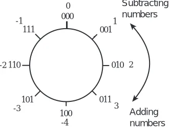
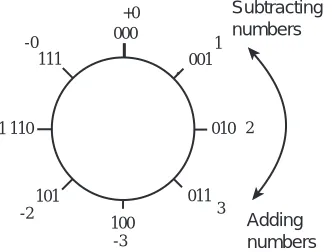
small as desired—the number line goes to ±∞, so the real number line can accommodate numbers of any size. On the other hand, as discussed in Chapter 2, computers represent data using a finite number of bits, and as a result can only store numbers within a certain range. For example, an examination of Table 2.1 shows that if we restrict the size of a number to, for example, 3 bits, there will only be eight possible two’s complement values that the number can assume. In Figure 3-1 these values are arranged in a circle beginning with 000 and proceed-ing around the circle to 111 and then back to 000. The figure also shows the dec-imal equivalents of these same numbers.
Some experimentation with the number circle shows that numbers can be added or subtracted by traversing the number circle clockwise for addition and
counter-100
010 110
000 111
101 011
001 0
1
2
3
-4 -3
-2 -1
Adding numbers Subtracting numbers
CHAPTER 3 ARITHMETIC 67
clockwise for subtraction. Numbers can also be subtracted by two’s complement-ing the subtrahend and addcomplement-ing. Notice that overflow can only occur for addition when the operands (“addend” and “augend”) are of the same sign. Furthermore, overflow occurs if a transition is made from +3 to −4 while proceeding around the number circle when adding, or from −4 to +3 while subtracting. (Two’s com-plement overflow is discussed in more detail later in the chapter.)
Here are two examples of 8-bit two’s complement addition, first using two posi-tive numbers:
0 0 0 0 1 0 1 0 (+10)10 + 0 0 0 1 0 1 1 1 (+23)10 ———————
0 0 1 0 0 0 0 1 (+33)10
A positive and a negative number can be added in a similar manner:
0 0 0 0 0 1 0 1 (+5)10 + 1 1 1 1 1 1 1 0 (−2)10 ___________
Discard carry →(1) 0 0 0 0 0 0 1 1 (+3)10
The carry produced by addition at the highest (leftmost) bit position is discarded in two’s complement addition. A similar situation arises with a carry out of the highest bit position when adding two negative numbers:
1 1 1 1 1 1 1 1 (−1)10 + 1 1 1 1 1 1 0 0 (−4)10 ——————
Discard carry →(1) 1 1 1 1 1 0 1 1 (−5)10
The carry out of the leftmost bit is discarded because the number system is mod-ular—it “wraps around” from the largest positive number to the largest negative number as Figure 3-1 shows.
68 CHAPTER 3 ARITHMETIC
correct results in spite of the fact that there is a carry-out of the MSB. The next section discusses overflow in two’s complement addition in more detail.
Overflow
When two numbers are added that have large magnitudes and the same sign, an overflow will occur if the result is too large to fit in the number of bits used in the representation. Consider adding (+80)10 and (+50)10 using an eight bit for-mat. The result should be (+130)10, however, as shown below, the result is (−126)10:
+ 0 1 0 1 0 0 0 0 (+80)10 + 0 0 1 1 0 0 1 0 (+50)10 ———————
+ 1 0 0 0 0 0 1 0 (−126)10
This should come as no surprise, since we know that the largest positive 8-bit two’s complement number is +(127)10, and it is therefore impossible to represent (+130)10. Although the result 100000102 “looks” like 13010 if we think of it in unsigned form, the sign bit indicates a negative number in the signed form, which is clearly wrong.
In general, if two numbers of opposite signs are added, then an overflow cannot occur. Intuitively, this is because the magnitude of the result can be no larger than the magnitude of the larger operand. This leads us to the definition of two’s complement overflow:
If the numbers being added are of the same sign and the result is of the opposite sign, then an overflow occurs and the result is incorrect. If the numbers being added are of opposite signs, then an overflow will never occur. As an alternative method of detecting overflow for addition, an overflow occurs if and only if the carry into the sign bit differs from the carry out of the sign bit.
CHAPTER 3 ARITHMETIC 69
3.2.2 HARDWARE IMPLEMENTATION OF ADDERS AND SUBTRACTORS
Up until now we have focused on algorithms for addition and subtraction. Now we will take a look at implementations of simple adders and subtractors.
Ripple-Carry Addition and Ripple-Borrow Subtraction
In Appendix A, a design of a four-bit ripple-carry adder is explored. The adder is modeled after the way that we normally perform decimal addition by hand, by summing digits in one column at a time while moving from right to left. In this section, we review the ripple-carry adder, and then take a look at a ripple-bor-row subtractor. We then combine the two into a single addition/subtraction unit.
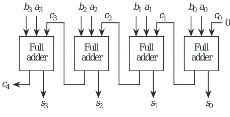
Figure 3-2 shows a 4-bit ripple-carry adder that is developed in Appendix A. Two
binary numbers A and B are added from right to left, creating a sum and a carry at the outputs of each full adder for each bit position.
Four 4-bit ripple-carry adders are cascaded in Figure 3-3 to add two 16-bit num-bers. The rightmost full adder has a carry-in of 0. Although the rightmost full adder can be simplified as a result of the carry-in of 0, we will use the more gen-eral form and force c0 to 0 in order to simplify subtraction later on.
Subtraction of binary numbers proceeds in a fashion analogous to addition. We can subtract one number from another by working in a single column at a time, subtracting digits of the subtrahendbi, from the minuendai, as we move from right to left. As in decimal subtraction, if the subtrahend is larger than the minu-end or there is a borrow from a previous digit then a borrow must be propagated
Full adder
b0a0
s0
Full adder
b1a1
s1
Full adder
b2a2
s2
Full adder
b3a3
c4
s3
0
c0 c1
c2 c3
70 CHAPTER 3 ARITHMETIC
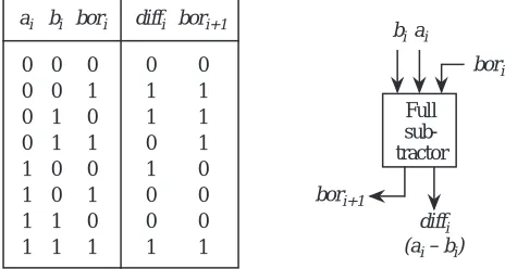
to the next most significant bit. Figure 3-4 shows the truth table and a “black-box” circuit for subtraction.
Full subtractors can be cascaded to form ripple-borrow subtractors in the same manner that full adders are cascaded to form ripple-carry adders. Figure 3-5
illus-s0 b1 a1 s1 b2 a2 s2 b3 a3 c4 s3 0 4-Bit Adder #0
b0 a0 s12 b13 a13 s13 b14 a14 s14 b15 a15 c16 s15
4-Bit Adder #3
b12 a12
. . .
c12 c0
Figure 3-3 A 16-bit adder is made up of a cascade of four 4-bit ripple-carry adders.
0 0 1 1 0 0 1 1 0 1 0 1 0 1 0 1
bi bori
0 0 0 0 1 1 1 1 ai 0 1 1 0 1 0 0 1 diffi 0 1 1 1 0 0 0 1 bori+1 Full sub-tractor
biai
bori
bori+1
diffi (ai – bi)
Figure 3-4 Truth table and schematic symbol for a ripple-borrow subtractor.
b0a0
diff0 b1a1
diff1 b2a2
diff2
Full sub-tractor
b3a3
bor4 diff3 0 Full sub-tractor Full sub-tractor Full sub-tractor bor0
CHAPTER 3 ARITHMETIC 71
trates a four-bit ripple-borrow subtractor that is made up of four full subtractors.
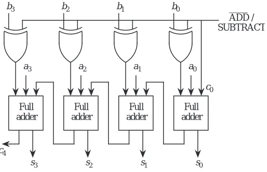
As discussed above, an alternative method of implementing subtraction is to form the two’s complement negative of the subtrahend and add it to the minu-end. The circuit that is shown in Figure 3-6 performs both addition and
subtrac-tion on four-bit two’s complement numbers by allowing the bi inputs to be complemented when subtraction is desired. An /SUBTRACT control line determines which function is performed. The bar over the ADD symbol indi-cates the ADD operation is active when the signal is low. That is, if the control line is 0, then the ai and bi inputs are passed through to the adder, and the sum is generated at the si outputs. If the control line is 1, then the ai inputs are passed through to the adder, but the bi inputs are one’s complemented by the XOR gates before they are passed on to the adder. In order to form the two’s comple-ment negative, we must add 1 to the one’s complecomple-ment negative, which is accomplished by setting the carry_in line (c0) to 1 with the control input. In this way, we can share the adder hardware among both the adder and the subtractor.
3.2.3 ONE’S COMPLEMENT ADDITION AND SUBTRACTION
Although it is not heavily used in mainstream computing anymore, the one’s complement representation was used in early computers. One’s complement addition is handled somewhat differently from two’s complement addition: the carry out of the leftmost position is not discarded, but is added back into the least significant position of the integer portion as shown in Figure 3-7. This is
Full adder
b0
a0
s0
Full adder
b1
a1
s1
Full adder
b2
a2
s2
Full adder
b3
a3
c4 s3
c0
ADD / SUBTRACT
Figure 3-6 Addition / subtraction unit.
72 CHAPTER 3 ARITHMETIC
known as an end-around carry.
We can better visualize the reason that the end-around carry is needed by exam-ining the 3-bit one’s complement number circle in Figure 3-8. Notice that the
number circle has two positions for 0. When we add two numbers, if we traverse through both −0 and +0, then we must compensate for the fact that 0 is visited twice. The end-around carry advances the result by one position for this situa-tion.
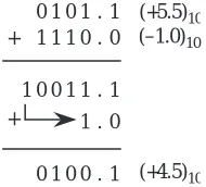
Notice that the distance between −0 and +0 on the number circle is the distance between two integers, and is not the distance between two successive represent-able numbers. As an illustration of this point, consider adding (5.5)10 and (−1.0)10 in one’s complement arithmetic, which is shown in Figure 3-9. (Note that we can also treat this as a subtraction problem, in which the subtrahend is negated by complementing all of the bits, before adding it to the minuend.) In
+
1 1 0
0 0 1
0 0 1
0 1 0
0 1 1
0
(–12)10 (+13)10
+
0000 1
1 (+1)10
End-around carry
Figure 3-7 An example of one’s complement addition with an end-around carry.
100
010 110
000 111
101 011
001 +0
1
2
3
-3 -2
-1 -0
Adding numbers Subtracting numbers
CHAPTER 3 ARITHMETIC 73
order to add (+5.5)10 and (−1.0)10 and obtain the correct result in one’s comple-ment, we add the end-around carry into the one’s position as shown. This adds complexity to our number circle, because in the gap between +0 and −0, there are valid numbers that represent fractions that are less than 0, yet they appear on the number circle before −0 appears. If the number circle is reordered to avoid this anomaly, then addition must be handled in a more complex manner.
The need to look for two different representations for zero, and the potential need to perform another addition for the end-around carry are two important reasons for preferring the two’s complement arithmetic to one’s complement arithmetic.
3.3 Fixed Point Multiplication and Division
Multiplication and division of fixed point numbers can be accomplished with addition, subtraction, and shift operations. The sections that follow describe methods for performing multiplication and division of fixed point numbers in both unsigned and signed forms using these basic operations. We will first cover unsigned multiplication and division, and then we will cover signed multiplica-tion and division.
3.3.1 UNSIGNED MULTIPLICATION
Multiplication of unsigned binary integers is handled similar to the way it is car-ried out by hand for decimal numbers. Figure 3-10 illustrates the multiplication process for two unsigned binary integers. Each bit of the multiplier determines whether or not the multiplicand, shifted left according to the position of the multiplier bit, is added into the product. When two unsigned n-bit numbers are multiplied, the result can be as large as 2n bits. For the example shown in Figure 3-10, the multiplication of two four-bit operands results in an eight-bit product. When two signed n-bit numbers are multiplied, the result can be as large as only
1 0 1
0 1 1
0 0 1
1 1 0
1 . .
.
(+5.5)10 (–1.0)10
+
(+4.5)10 1
0
1 +
010 1
0 .
. 0
1
2(n-1)+1 = (2n-1) bits, because this is equivalent to multiplying two (n-1)-bit unsigned numbers and then introducing the sign bit.
A hardware implementation of integer multiplication can take a similar form to the manual method. Figure 3-11 shows a layout of a multiplication unit for
four-bit numbers, in which there is a four-bit adder, a control unit, three four-bit registers, and a one-bit carry register. In order to multiply two numbers, the mul-tiplicand is placed in the M register, the multiplier is placed in the Q register, and the A and C registers are cleared to zero. During multiplication, the rightmost bit of the multiplier determines whether the multiplicand is added into the product at each step. After the multiplicand is added into the product, the multiplier and the A register are simultaneously shifted to the right. This has the effect of shift-ing the multiplicand to the left (as for the manual process) and exposshift-ing the next bit of the multiplier in position q0.
Figure 3-12 illustrates the multiplication process. Initially, C and A are cleared,
1 1 0 1 1 0 1 1
×
1 1 0 1 1 1 0 1 0 0 0 0 1 1 0 1 1 0 0 0 1 1 1 1
(11)10
(13)10 Multiplicand M Multiplier Q
(143)10 Product P
Partial products
Figure 3-10 Multiplication of two unsigned binary integers.
Multiplicand (M)
m0 m1 m2 m3
a0
a1
a2
a3 q3 q2 q1 q0
Multiplier (Q) C
4–Bit Adder
Shift and Add Control
Logic Add
4
4
4
Shift Right
q0
A Register
and M and Q hold the multiplicand and multiplier, respectively. The rightmost bit of Q is 1, and so the multiplier M is added into the product in the A register. The A and Q registers together make up the eight-bit product, but the A register is where the multiplicand is added. After M is added to A, the A and Q registers are shifted to the right. Since the A and Q registers are linked as a pair to form the eight-bit product, the rightmost bit of A is shifted into the leftmost bit of Q. The rightmost bit of Q is then dropped, C is shifted into the leftmost bit of A, and a 0 is shifted into C.
The process continues for as many steps as there are bits in the multiplier. On the second iteration, the rightmost bit of Q is again 1, and so the multiplicand is added to A and the C/A/Q combination is shifted to the right. On the third iter-ation, the rightmost bit of Q is 0 so M is not added to A, but the C/A/Q combi-nation is still shifted to the right. Finally, on the fourth iteration, the rightmost bit of Q is again 1, and so M is added to A and the C/A/Q combination is shifted to the right. The product is now contained in the A and Q registers, in which A holds the high-order bits and Q holds the low-order bits.
3.3.2 UNSIGNED DIVISION
In longhand binary division, we must successively attempt to subtract the divisor from the dividend, using the fewest number of bits in the dividend as we can. Figure 3-13 illustrates this point by showing that (11)2 does not “fit” in 0 or 01,
C 0
0 0
1 0
0
1 0
0 A 0 0 0
1 1 0 1 0 1 1 0
0 0 1 1 1 0 0 1
0 1 0 0
0 0 0 1 1 0 0 0
1 Q 0 1 1
1 0 1 1 1 1 0 1
1 1 0 1 1 1 1 0
1 1 1 1
1 1 1 1 1 1 1 1 Multiplicand (M):
1 1 0 1
Initial values
Add M to A Shift
Add M to A Shift
Shift (no add)
Add M to A Shift
Product
but does fit in 011 as indicated by the pattern 001 that starts the quotient.
Computer-based division of binary integers can be handled similar to the way that binary integer multiplication is carried out, but with the complication that the only way to tell if the dividend does not “fit” is to actually do the subtraction and test if the remainder is negative. If the remainder is negative then the sub-traction must be “backed out” by adding the divisor back in, as described below.
In the division algorithm, instead of shifting the product to the right as we did for multiplication, we now shift the quotient to the left, and we subtract instead of adding. When two n-bit unsigned numbers are being divided, the result is no larger than n bits.
Figure 3-14 shows a layout of a division unit for four-bit numbers in which there
is a five-bit adder, a control unit, a four-bit register for the dividend Q, and two five-bit registers for the divisor M and the remainder A. Five-bit registers are used for A and M, instead of 4-bit registers as we might expect, because an extra bit is
1 1
0 0 1 0 0 1 1 1 1 1
0 R 1
1
Figure 3-13 Example of base 2 division.
Divisor (M)
m0
m1
m2
m3
a0 a1 a2
a3 q3 q2 q1 q0
Dividend (Q) 5–Bit Adder
Shift and Add / Sub Control Logic Add /
Sub 5
5
5
Shift Left
q0
A Register
a4
0
a4
needed to indicate the sign of the intermediate result. Although this division method is for unsigned numbers, subtraction is used in the process and negative partial results sometimes arise, which extends the range from −16 through +15, thus there is a need for 5 bits to store intermediate results.
In order to divide two four-bit numbers, the dividend is placed in the Q register, the divisor is placed in the M register, and the A register and the high order bit of M are cleared to zero. The leftmost bit of the A register determines whether the divisor is added back into the dividend at each step. This is necessary in order to restore the dividend when the result of subtracting the divisor is negative, as described above. This is referred to as restoring division, because the dividend is restored to its former value when the remainder is negative. When the result is not negative, then the least significant bit of Q is set to 1, which indicates that the divisor “fits” in the dividend at that point.
Figure 3-15 illustrates the division process. Initially, A and the high order bit of M are cleared, and Q and the low order bits of M are loaded with the dividend and divisor, respectively. The A and Q registers are shifted to the left as a pair and the divisor M is subtracted from A. Since the result is negative, the divisor is added back to restore the dividend, and q0 is cleared to 0. The process repeats by shifting A and Q to the left, and by subtracting M from A. Again, the result is negative, so the dividend is restored and q0 is cleared to 0. On the third iteration, A and Q are shifted to the left and M is again subtracted from A, but now the result of the subtraction is not negative, so q0 is set to 1. The process continues for one final iteration, in which A and Q are shifted to the left and M is sub-tracted from A, which produces a negative result. The dividend is restored and q0 is cleared to 0. The quotient is now contained in the Q register and the remain-der is contained in the A register.
3.3.3 SIGNED MULTIPLICATION AND DIVISION
If we apply the multiplication and division methods described in the previous sections to signed integers, then we will run into some trouble. Consider multi-plying −1 by +1 using four-bit words, as shown in the left side of Figure 3-16. The eight-bit equivalent of +15 is produced instead of −1. What went wrong is that the sign bit did not get extended to the left of the result. This is not a prob-lem for a positive result because the high order bits default to 0, producing the correct sign bit 0.
prod-uct is extended to the width of the result, and only the rightmost eight bits of the result are retained. If both operands are negative, then the signs are extended for both operands, again retaining only the rightmost eight bits of the result.
Signed division is more difficult. We will not explore the methods here, but as a
0 0 1 0 0 0 A 0 0 0
0 0 0 0 1 1 0 1
0 0 1 1 0 0 0 0
0 Q 1 1 1
1 1 1 0 1 1 1 0
1 0 0 0 1 0 0 0 Divisor (M):
0 0 1 1
Initial values
Shift left
Subtract M from A
Shift left
Subtract M from A 0 0 0 0 0 1 1 1 0 Restore A (Add M to A)
0 1
0 0 0 1 1 1 1 0
1 1 0 0 1 1 0 0
Shift left
Subtract M from A 0 0 0 0 1 1 1 0 0 Restore A 0 0 0 0 0 1 1 1 0 Clear q0
0 0 0 0 1 1 1 0 0 Clear q0
0 0 0 0 0 1 0 0 1 Set q0
0 1
0 0 0 1 1 1 1 0
0 0 1 0 0 0 1 0
Shift left
Subtract M from A 0 0 0 0 1 0 0 1 0 Restore A 0 0 0 0 1 0 0 1 0 Clear q0
Remainder Quotient 0
Figure 3-15 An example of division using the serial divider.
1 1 1 1 0 0 0 1
×
1 1 1 1 0 0 0 0 0 0 0 0 0 0 0 0 0 0 0 0 1 1 1 1
(+1)10
(–1)10
(+15)10
(Incorrect; result should be –1)
1 1 1 1 0 0 0 1
×
1 1 1 1 0 0 0 0 0 0 0 0 0 0 0 0 1 1 1 1 1 1 1 1
(+1)10
(–1)10
(–1)10
1 1 1 1
1 1 1 1 0 0 0 0 0 0
general technique, we can convert the operands into their positive forms, per-form the division, and then convert the result into its true signed per-form as a final step.
3.4 Floating Point Arithmetic
Arithmetic operations on floating point numbers can be carried out using the fixed point arithmetic operations described in the previous sections, with atten-tion given to maintaining aspects of the floating point representaatten-tion. In the sec-tions that follow, we explore floating point arithmetic in base 2 and base 10, keeping the requirements of the floating point representation in mind.
3.4.1 FLOATING POINT ADDITION AND SUBTRACTION
Floating point arithmetic differs from integer arithmetic in that exponents must be handled as well as the magnitudes of the operands. As in ordinary base 10 arithmetic using scientific notation, the exponents of the operands must be made equal for addition and subtraction. The fractions are then added or subtracted as appropriate, and the result is normalized.
This process of adjusting the fractional part, and also rounding the result can lead to a loss of precision in the result. Consider the unsigned floating point addition (.101 × 23 + .111 × 24) in which the fractions have three significant dig-its. We start by adjusting the smaller exponent to be equal to the larger exponent, and adjusting the fraction accordingly. Thus we have .101 × 23 = .010 × 24, los-ing .001 × 23 of precision in the process. The resulting sum is
(.010 + .111) × 24 = 1.001 × 24 = .1001 × 25,
and rounding to three significant digits, .100 × 25, and we have lost another 0.001 × 24 in the rounding process.
Why do floating point numbers have such complicated formats?
from the form it takes in storage. (See Chapter 2 for a description of the IEEE 754 floating point format.) The exponent and mantissa must be extracted from the packed bit pattern before an arithmetic operation can be performed; after the arithmetic operation(s) are performed, the result must be renormalized and rounded, and then the bit patterns are re-packed into the requisite format.
The virtue of a floating point format that contains a sign bit followed by an exponent in excess notation, followed by the magnitude of the mantissa, is that two floating point numbers can be compared for >, <, and = without unpacking. The sign bit is most important in such a comparison, and it appropriately is the MSB in the floating point format. Next most important in comparing two num-bers is the exponent, since a change of ± 1 in the exponent changes the value by a factor of 2 (for a base 2 format), whereas a change in even the MSB of the frac-tional part will change the value of the floating point number by less than that.
In order to account for the sign bit, the signed magnitude fractions are repre-sented as integers and are converted into two’s complement form. After the addi-tion or subtracaddi-tion operaaddi-tion takes place in two’s complement, there may be a need to normalize the result and adjust the sign bit. The result is then converted back to signed magnitude form.
3.4.2 FLOATING POINT MULTIPLICATION AND DIVISION
Floating point multiplication and division are performed in a manner similar to floating point addition and subtraction, except that the sign, exponent, and frac-tion of the result can be computed separately. If the operands have the same sign, then the sign of the result is positive. Unlike signs produce a negative result. The exponent of the result before normalization is obtained by adding the exponents of the source operands for multiplication, or by subtracting the divisor exponent from the dividend exponent for division. The fractions are multiplied or divided according to the operation, followed by normalization.
Consider using three-bit fractions in performing the base 2 computation: (+.101 × 22) × (−.110 × 2-3). The source operand signs differ, which means that the result will have a negative sign. We add exponents for multiplication, and so the exponent of the result is 2 + −3 = −1. We multiply the fractions, which produces the product .01111. Normalizing the product and retaining only three bits in the fraction produces −.111 × 2−2.
(+.110 × 25) / (+.100 × 24). The source operand signs are the same, which means that the result will have a positive sign. We subtract exponents for division, and so the exponent of the result is 5 – 4 = 1. We divide fractions, which can be done in a number of ways. If we treat the fractions as unsigned integers, then we will have 110/100 = 1 with a remainder of 10. What we really want is a contiguous set of bits representing the fraction instead of a separate result and remainder, and so we can scale the dividend to the left by two positions, producing the result: 11000/100 = 110. We then scale the result to the right by two positions to restore the original scale factor, producing 1.1. Putting it all together, the result of dividing (+.110 × 25) by (+.100 × 24) produces (+1.10 × 21). After normaliza-tion, the final result is (+.110 × 22).
3.5 High Performance Arithmetic
For many applications, the speed of arithmetic operations are the bottleneck to performance. Most supercomputers, such as the Cray, the Tera, and the Intel Hypercube are considered “super” because they excel at performing fixed and floating point arithmetic. In this section we discuss a number of ways to improve the speed of addition, subtraction, multiplication, and division.
3.5.1 HIGH PERFORMANCE ADDITION
The ripple-carry adder that we reviewed in Section 3.2.2 may introduce too much delay into a system. The longest path through the adder is from the inputs of the least significant full adder to the outputs of the most significant full adder. The process of summing the inputs at each bit position is relatively fast (a small two-level circuit suffices) but the carry propagation takes a long time to work its way through the circuit. In fact, the propagation time is proportional to the number of bits in the operands. This is unfortunate, since more significant fig-ures in an addition translates to more time to perform the addition. In this sec-tion, we look at a method of speeding the carry propagation in what is known as a carry lookahead adder.
In Appendix B, reduced Boolean expressions for the sum (si) and carry outputs (ci+1) of a full adder are created. These expressions are repeated below, with sub-scripts added to denote the relative position of a full adder in a ripple-carry adder:
We can factor the second equation and obtain:
which can be rewritten as:
where: Gi = aibi and Pi = ai + bi.
The Gi and Pi terms are referred to as generate and propagate functions, respec-tively, for the effect they have on the carry. When Gi = 1, a carry is generated at stage i. When Pi = 1, then a carry is propagated through stage i if either ai or bi is a 1. The Gi and Pi terms can be created in one level of logic since they only depend on an AND or an OR of the input variables, respectively.
The carries again take the most time. The carry c1 out of stage 0 is G0 + P0c0, and since c0 = 0 for addition, we can rewrite this as c1 = G0. The carry c2 out of stage 1 is G1 + P1c1, and since c1 = G0, we can rewrite this as: c2 = G1 + P1G0. The carry c3 out of stage 2 is G2 + P2c2, and since c2 = G1 + P1G0, we can rewrite this as: c3 = G2 + P2G1 + P2P1G0. Continuing one more time for a four-bit adder, the carry out of stage 3 is G3 + P3c3, and since c3 = G2 + P2G1 + P2P1G0, we can rewrite this as: c4 = G3 + P3G2 + P3P2G1 + P3P2P1G0.
We can now create a four-bit carry lookahead adder as shown in Figure 3-17. We still have the delay through the full adders as before, but now the carry chain is broken into independent pieces that require one gate delay for Gi and Pi and two more gate delays to generate ci+1. Thus, a depth of three gate delays is added, but the ripple-carry chain is removed. If we assume that each full adder introduces a gate delay of two, then a four-bit carry lookahead adder will have a maximum gate delay of five, whereas a four-bit ripple-carry adder will have a maximum gate delay of eight. The difference between the two approaches is more pronounced for wider operands. This process is limited to about eight bits of carry-lookahead, because of gate fanin limitations discussed in Appendix A. For additions of num-bers having more than eight bits, the carry-lookahead circuits can be cascaded to compute the carry in and carry out of each carry-lookahead unit. (See the EXAMPLE at the end of the chapter.)
ci+1 = bici+aici+aibi
ci+1 = aibi+(ai+bi)ci
3.5.2 HIGH PERFORMANCE MULTIPLICATION
A number of methods exist for speeding the process of multiplication. Two methods are described in the sections below. The first approach gains perfor-mance by skipping over blocks of 1’s, which eliminates addition steps. A parallel multiplier is described next, in which a cross product among all pairs of multi-plier and multiplicand bits is formed. The result of the cross product is summed by rows to produce the final product.
The Booth Algorithm
The Booth algorithm treats positive and negative numbers uniformly. It operates on the fact that strings of 0’s or 1’s in the multiplier require no additions – just shifting. Additions or subtractions take place at the boundaries of the strings, where transitions take place from 0 to 1 or from 1 to 0. A string of 1’s in the mul-tiplier from bit positions with weights 2u to 2v can be treated as 2u+1 – 2v. For example, if the multiplier is 001110 (+14)10, then u = 3 and v = 1, so 24 – 21 = 14.
Full adder
s0
Full adder
s1
Full adder
s2
Full adder
s3
0
c0 b3a3
b3a3 b2a2 b1a1 b0a0
G0 P1 G1
P2 G2
c1 c2
c3 P3 G3
c4
In a hardware implementation, the multiplier is scanned from right to left. The first transition is observed going from 0 to 1, and so 21 is subtracted from the ini-tial value (0). On the next transition, from 1 to 0, 24 is added, which results in +14. A 0 is considered to be appended to the right side of the multiplier in order to define the situation in which a 1 is in the rightmost digit of the multiplier.
If the multiplier is recoded according to the Booth algorithm, then fewer steps may be needed in the multiplication process. Consider the multiplication exam-ple shown in Figure 3-18. The multiplier (14)10 contains three 1’s, which means
that three addition operations are required for the shift/add multiplication proce-dure that is described in Section 3.3.1. The Booth recoded multiplier is obtained by scanning the original multiplier from right to left, and placing a −1 in the position where the first 1 in a string is encountered, and placing a +1 in the posi-tion where the next 0 is seen. The multiplier 001110 thus becomes 0 +1 0 0 −1 0. The Booth recoded multiplier contains just two nonzero digits: +1 and −1, which means that only one addition operation and one subtraction operation are needed, and so a savings is realized for this example.
A savings is not always realized, however, and in some cases the Booth algorithm may cause more operations to take place than if it is not used at all. Consider the example shown in Figure 3-19, in which the multiplier consists of alternating 1’s and 0’s. This is the same example shown in Figure 3-18 but with the multipli-cand and multiplier swapped. Without Booth recoding of the multiplier, three addition operations are required for the three 1’s in the multiplier. The Booth recoded multiplier, however, requires six addition and subtraction operations, which is clearly worse. We improve on this in the next section.
0 1 0 1 1 1 1 0
1 0 1 1 1
(14)10
(21)10 Multiplicand Multiplier
(294)10 Product 1 0 0 0 0 1
0 0−1 0
× Booth recoded
multiplier +1 0 Shift Add Shift Subtract Shift 1 1 1 1 0 1 0 1 0
0 0 1 1 1 0 0 1 0 0 0
(−21 × 2)10
(21 × 16)10 1 0 0 0 0 0 0 0 0
The Modified Booth Algorithm
One solution to this problem is to group the recoded multiplier bits in pairs, known as bit pair recoding, which is also known as the modified Booth algo-rithm. Grouping bit pairs from right to left produces three “+1,−1” pairs as shown in Figure 3-20. Since the +1 term is to the left of the −1 term, it has a
weight that is twice as large as the weight for the −1 position. Thus, we might think of the pair as having the collective value +2 – 1 = +1.
In a similar manner, the pair −1,+1 is equivalent to −2 + 1 = −1. The pairs +1,+1 and −1,−1 cannot occur. There are a total of seven pairs that can occur, which are shown in Figure 3-21. For each case, the value of the recoded bit pair is
multi-1 1 1 0 0 1 0 1
1 0 0 1 1
(21)10
(14)10 Multiplicand
Multiplier
(294)10 Product 0 1 1 0 0 1
+1 −1 +1 −1
× Booth recoded
multiplier −1 +1 Add Subtract 1 1 1 1 0 0 0 0 0
0 0 1 1 1 0 0 1 0 0 0
(−14 × 1)10 (14 × 2)10 1 0 0 0 0 0 0 1 1 1 0 0 1 1 1 1 1 1 1 0 0 0 0 0 0 0 0 1 1 1 0 0 1 1 1 1 1 0 0 0 0 0 0 1 1 0 0 0 0 0 0 0 0 0 0 0
0 (−14 × 4)10 (14 × 8)10
(−14 × 16)10 (14 × 32)10
Figure 3-19 A worst case Booth recoded multiplication example.
1 1 1 0 0 1 0 1
0
(14)10
(21)10 Multiplicand Multiplier
(294)10 Product 0
1 0 0
+1 −1 +1 −1
× +1 −1 Booth recoded multiplier
0 0 0 0 0
0 0 1 1 1 0 0 1 0 0 0
(14 × 1)10 0 0 0 0 1 1 1 0 1 1 1 1 0 0 0 0 0 1 0 0 0 0 0 0 0 0 1 0 0 0
0 (14× 4)10 (14 × 16)10
Bit pair recoded multiplier +1 +1
+1
plied by the multiplicand and is added to the product. In an implementation of bit pair recoding, the Booth recoding and bit pair recoding steps are collapsed into a single step, by observing three multiplier bits at a time, as shown in the corresponding multiplier bit table.
The process of bit pair recoding of a multiplier guarantees that in the worst case, only w/2 additions (or subtractions) will take place for a w-bit multiplier.
Array Multipliers
The serial method we used for multiplying two unsigned integers in Section 3.2.1 requires only a small amount of hardware, but the time required to multi-ply two numbers of length w grows as w2. We can speed the multiplication pro-cess so that it completes in just 2w steps by implementing the manual propro-cess shown in Figure 3-10 in parallel. The general idea is to form a one-bit product between each multiplier bit and each multiplicand bit, and then sum each row of partial product elements from the top to the bottom in systolic (row by row) fashion.
The structure of a systolic array multiplier is shown in Figure 3-22. A partial product (PP) element is shown at the bottom of the figure. A multiplicand bit (mi) and a multiplier bit (qj) are multiplied by the AND gate, which forms a par-tial product at position (i,j) in the array. This parpar-tial product is added with the partial product from the previous stage (bj) and any carry that is generated in the previous stage (aj). The result has a width of 2w, and appears at the bottom of the array (the high order w bits) and at the right of the array (the low order w bits).
0 0 0 +1 +1 +1
−1
−1
−1 0 +1
−1 0 +1
−1 0 +1
−1 = = = = = = = = =
0 +1
−1 +2 –– +1
−2
−1 –– Recoded bit pair (i) Booth pair
(i + 1, i)
Corresponding multiplier bits (i + 1, i, i − 1)
000 or 111 001 110 011
010 100 101
3.5.3 HIGH PERFORMANCE DIVISION
We can extend the unsigned integer division technique of Section 3.3.2 to pro-duce a fractional result in computing a/b. The general idea is to scale a and b to look like integers, perform the division process, and then scale the quotient to
. . . q
0 q0 q0 q0
0 0 0 0 0 0 0 0
m0 m1
m2
mw Multiplicand
0
. . .
p0
q
1 q1 q1 q1
p1
qw qw qw qw
. . .
0
p2w-1
pw+3
pw+2 pw+1 0
pw .
. . .
. . .
. .
Multiplier
Product 0
Full adder
Carry-in
Carry-out
sum
qj aj bj
mout
mi
mi
PP0,w PP0,2 PP0,1 PP0,0
PP1,w PP1,2 PP1,1 PP1,0
PPw,w PPw,2 PPw,1 PPw,0
FA FA FA FA
w+1,0 w+1,1
w+1,2 w+1,w
PP PP PP PP
correspond to the actual result of dividing a by b.
A faster method of division makes use of a lookup table and iteration. An itera-tive method of finding a root of a polynomial is called Newton’s iteration, which is illustrated in Figure 3-23. The goal is to find where the function f(x) crosses the
x axis by starting with a guess xi and then using the error between f(xi) and zero
to refine the guess.
The tangent line at f(xi) can be represented by the equation:
y − f(xi) = f ’(xi)(x − xi).
The tangent line crosses the x axis at:
The process repeats while f(x) approaches zero.
The number of bits of precision doubles on each iteration (see [Goldberg, 1990]), and so if we are looking to obtain 32 bits of precision and we start with a single bit of precision, then five iterations are required to reach our target preci-sion. The problem now is to cast division in the form of finding a zero for f(x).
Consider the function 1/x − b which has a zero at 1/b. If we start with b, then we can compute 1/b by iteratively applying Newton’s method. Since f ’(x) = −1/x2,
f(x)
x xi+1
xi
Figure 3-23 Newton’s iteration for zero finding. Adapted from [Goldberg, 1990].
xi+1 xi
f x( )i f′( )xi
we now have:
Thus, we only need to perform multiplication and subtraction in order to per-form division. Further, if our initial guess for x0 is good enough, then we may only need to perform the iteration a few times.
Before using this method on an example, we need to consider how we will obtain our initial guess. If we are working with normalized fractions, then it is relatively easy to make use of a lookup table for the first few digits. Consider computing 1/.101101 using a 16-bit normalized base 2 fraction in which the leading 1 is not hidden. The first three bits for any binary fraction will be one of the patterns: .100, .101, .110, or .111. These fractions correspond to the base 10 numbers 1/2, 5/8, 3/4, and 7/8, respectively. The reciprocals of these numbers are 2, 8/5, 4/3, and 8/7, respectively. We can store the binary equivalents in a lookup table, and then retrieve x0 based on the first three bits of b.
The leading 1 in the fraction does not contribute to the precision, and so the leading three bits of the fraction only provide two bits of precision. Thus, the lookup table only needs two bits for each entry, as shown in Figure 3-24.
Now consider computing 1/.1011011 using this floating point representation. We start by finding x0 using the table shown in Figure 3-24. The first three bits of the fraction b are 101, which corresponds to x0 = 01. We compute x1 = x0(2 −
x0b) and obtain, in unsigned base 2 arithmetic: x1 = 01(10 − (01)(.1011011)) = 1.0100101. Our two bits of precision have now become four bits of precision. For this example, we will retain as much intermediate precision as we can. In general, we only need to retain at most 2p bits of intermediate precision for a
p-bit result. We iterate again, obtaining eight bits of precision:
xi+1 xi
1⁄xi–b
1⁄xi2 –
---– xi+xi–xi2b x
i(2–xib)
= = =
.100 2 10
B = First three bits of b
Corresponding lookup table entry Actual base 10
value of 1/B
.101 1 3/5 01
.110 1 1/3 01
.111 1 1/7 01
x2 = x1(2 − x1b) = 1.0100101(10 − (1.0100101)(.1011011))
= 1.011001011001001011101.
We iterate again, obtaining our target 16 bits of precision:
x3 = x2(2 − x2b) = (1.011001011001001011101)(2 −
(1.011001011001001011101)(.1011011)) = 1.011010000001001
= (1.40652466)10. The precise value is (1.40659341)10, but our 16-bit value is as close to the precise value as it can be.
3.5.4 RESIDUE ARITHMETIC
Addition, subtraction, and multiplication can all be performed in a single, carry-less step using residue arithmetic. The residue number system is based on rela-tively prime integers called moduli. The residue of an integer with respect to a particular modulus is the least positive integer remainder of the division of the integer by the modulus. A set of possible moduli are 5, 7, 9, and 4. With these moduli, 5 × 7 × 9 × 4 = 1260 integers can be uniquely represented. A table show-ing the representation of the first twenty decimal integers usshow-ing moduli 5, 7, 9, and 4 is shown in Figure 3-25.
Addition and multiplication in the residue number system result in valid residue numbers, provided the size of the chosen number space is large enough to
con-Decimal Residue Decimal Residue 5794
0 0000 10 0312
5794
1 1111 11 1423
2 2222 12 2530
3 3333 13 3641
4 4440 14 4052
5 0551 15 0163
6 1662 16 1270
7 2073 17 2381
8 3180 18 3402
9 4201 19 4513
tain the results. Subtraction requires each residue digit of the subtrahend to be complemented with respect to its modulus before performing addition. Addition and multiplication examples are shown in Figure 3-26. For these examples, the
moduli used are 5, 7, 9, and 4. Addition is performed in parallel for each col-umn, with no carry propagation. Multiplication is also performed in parallel for each column, independent of the other columns.
Although residue arithmetic operations can be very fast, there are a number of disadvantages to the system. Division and sign detection are difficult, and a rep-resentation for fractions is also difficult. Conversions between the residue num-ber system and weighted numnum-ber systems are complex, and often require involved methods such as the Chinese remainder theorem. The conversion problem is important because the residue number system is not very useful with-out being translated to a weighted number system so that magnitude compari-sons can be made. However, for integer applications in which the time spent in addition, subtraction, and multiplication outweighs the time spent in division, conversion, etc., the residue number system may be a practical approach. An important application area is matrix-vector multiplication, which is used exten-sively in signal processing.
EXAMPLE: WIDE WORD HIGH PERFORMANCE
ADDER
A practical word width for a carry lookahead adder (CLA) is four bits, whereas a 16-bit word width is not as practical because of the large fan-ins and fan-outs of the internal logic. We can subdivide a 16-bit addition problem into four 4-bit groups in which carry lookahead is used within the groups, and in which carry lookahead is also used among the groups. This organization is referred to as a group carry lookahead adder (GCLA). For this example, we will compare a
Decimal Residue 5794
29 4121
27 2603
56 1020
29 + 27 = 56
Decimal Residue 5794
10 0312
17 2381
170 0282 10 × 17 = 170
16-bit CLA with a 16-bit GCLA in terms of gate delays, fan-ins, and fan-outs.
Figure 3-27 shows a 16-bit GCLA that is composed of four 4-bit CLAs, with
some additional logic that generates the carries between the four-bit groups. Each group behaves as an ordinary CLA, except that the least significant carry into each CLA is treated as a variable instead of as a 0, and that group generate (GG) and group propagate (GP) signals are generated. A GG signal is generated when a carry is generated somewhere within a group, and all of the more signifi-cant propagate signals are true. This means that a carry into a group will propa-gate all the way through the group. The corresponding equations for the least significant GG and GP signals in Figure 3-27 are shown below:
GG0 = G3 + P3G2 + P3P2G1 + P3P2P1G0
GP0 = P3P2P1P0
The remaining GG and GP signals are computed similarly.
The carry into each group, except for the carry into CLA0, is computed from the GG and GP signals. For example, c4 is true when GG0 is true or when GP0 and
c0 are both true. The corresponding equation is:
c4 = GG0 + GP0c0.
c16 Group Carry Lookahead Logic
CLA0 4
a0 – a3
4
b0 – b3
4
s0 – s3
GG0 GP0
CLA1 4
a4 – a7
4
b4 – b7
4
s4 – s7
GG1 GP1
CLA2 4
a8 – a11
4
b8 – b11
4
s8 – s11
GG2 GP2
CLA3 4
a12 – a15
4
b12 – b15
4
s12 – s15
GG3 GP3
c4
c8
c12
c0
Higher order carries out of each group are computed in a similar manner:
c8 = GG1 + GP1c4 = GG1 + GP1GG0 + GP1GP0c0.
c12 = GG2 + GP2c8 = GG2 + GP2GG1 + GP2GP1GG0 +
GP2GP1GP0c0.
c16 = GG3 + GP3c12 = GG3 + GP3GG2 + GP3GP2GG1 +
GP3GP2GP1GG0 + GP3GP2GP1GP0c0.
In terms of gate delays, a 16-bit CLA has a longest path of five gate delays to pro-duce the most significant sum bit, as discussed in Section 3.5.1. Each of the CLAs in the 16-bit GCLA also has at least five gate delays on the longest path. The GG and GP signals are generated in three gate delays, and the carry signals out of each group are generated in two more gate delays, resulting in a total of five gate delays to generate the carry out of each group. In the highest bit posi-tion (s15), five gate delays are needed to generate c12, and another five gate delays are needed to generate s15, for a worst case path of 10 gate delays through the 16-bit GCLA.
With regard to fan-in and fan-out, the maximum fan-in of any gate in a four-bit CLA is four (refer to Figure 3-17), and in general, the maximum fan-in of any gate in an n-bit CLA is n. Thus, the maximum fan-in of any gate in a 16-bit CLA is 16. In comparison, the maximum fan-in for a 16-bit GCLA is five (for generating c16). The fan-outs for both cases are the same as the fan-ins.
In summary, the 16-bit CLA has only half of the depth of the 16-bit GCLA (five gate delays vs. 10 gate delays). The highest fan-in for a 16-bit CLA is 16, which is more than three times the highest fan-in for a 16-bit GCLA (16 vs. five). The highest fan-outs are the same as the highest fan-ins for each case. ■
3.6 Case Study: Calculator Arithmetic Using Binary Coded Decimal
3.6.1 THE HP9100A CALCULATOR
The popular HP9100A calculator, which came out in the late 1960’s, performed the basic arithmetic functions: addition, subtraction, multiplication, and divi-sion, as well as square root, ex, ln x, log x, trigonometric functions, and other functions, all using base 10 arithmetic. The HP9100A is actually a desktop cal-culator (see Figure 3-28), but was considered small for what it accomplished with
the technology of the day. The HP9100 display shows 10 significant digits, but all calculations are performed to 12 significant digits, with the two last significant digits (which are known as guard digits) being used for truncation and round-off errors. Although the HP9100A may seem like a relic today, the arith-metic methods are still relevant.
The next two sections describe general techniques for performing fixed point and floating point BCD addition and subtraction. Other calculator operations described in the remaining sections are performed in a similar manner, making use of the addition and subtraction operations.
3.6.2 BINARY CODED DECIMAL ADDITION AND SUBTRACTION
Consider adding (+255)10 and (+63)10 in BCD representation, as illustrated in Figure 3-29. Each base 10 digit occupies four bit positions, and addition is per-formed on a BCD digit by BCD digit basis (not bit by bit), from right to left, as we would normally carry it out by hand using a decimal representation. The result, (+318)10, is produced in BCD form as shown.
Subtraction in BCD is handled similar to the way subtraction is handled in two’s complement (adding the negative of the subtrahend) except that ten’s comple-ment is used instead of two’s complecomple-ment. Consider performing the subtraction operation (255 − 63 = 192)10. We can cast this into the addition problem (255 + (−63) = 192)10. We start by forming the nine’s complement of 63:
We then add 1 in order to form the 10’s complement:
The addition operation can now be performed, as shown in Figure 3-30. Notice
that the carry out of the highest digit position is discarded, as in two’s comple-ment addition.
0 0 0 0
(0)10
0 0 1 0
(2)10
0 1 0 1
(5)10
0 1 0 1
(5)10
(+255)10
0 0 0 0
(0)10
0 0 0 0
(0)10
0 1 1 0
(6)10
0 0 1 1
(3)10
(+63)10 +
0 0 0 0
(0)10
0 0 1 1
(3)10
0 0 0 1
(1)10
1 0 0 0
(8)10
(+318)10
0 1 0 0 Carries
Figure 3-29 An addition example using binary coded decimal.
9 9 9 9 0 0 6 3 9 9 3 6
−
9 9 3 6 0 0 0 1 9 9 3 7
+
0 0 0 0 0 0 1 0 0 1 0 1 0 1 0 1 (+255)10
1 0 0 1 1 0 0 1 0 0 1 1 0 1 1 1 (−63)10
+
0 0 0 0 0 0 0 1 1 0 0 1 0 0 1 0 (+192)10
1 0 1 0 Carries
1
1
Discard carry
Unlike the two’s complement representation, we cannot simply look at the left-most bit to determine the sign. In ten’s complement, the number is positive if the leftmost digit is between 0 and 4, inclusive, and is negative otherwise. (The BCD bit patterns for 4 and 5 are 0100 and 0101, respectively, which both have a 0 in the leftmost bit, yet 4 indicates a positive number and 5 indicates a negative number.) If we use an excess 3 encoding for each digit, then the leftmost bit will indicate the sign. Figure 3-31 shows the encoding. Notice that six of the bit
pat-terns cannot occur, and so they are marked as don’t cares, ‘d’.
Now consider the design of a BCD full adder. The BCD full adder should sum two BCD digits and a carry-in, and should produce a sum BCD digit and a carry-out, all using excess 3. A design using two’s complement full adders is shown in Figure 3-32. The excess 3 BCD digits are added in the upper four two’s complement full adders (FAs). Since each operand is represented in excess 3, the result is in excess 6. In order to restore the result to excess 3, we need to subtract 3 from the result. As an alternative, we can add 13 to the result since 16 − 3 = 16 + 13 in a four-bit representation, discarding the carry out of the highest bit posi-tion. The latter approach is used in Figure 3-32, in which 1310 = 11012 is added to the result. Note that this only works if there is no carry. When there is a carry, then we need to also subtract 10 (or equivalently, add 6) from the result, besides subtracting 3 (or adding 13) to restore the excess 3 representation, and produce a
0 0 1 1 0 0 1 1 0 0 1 1 0 0 1 1 0 1 0 1 0 1 0 1 0 1 0 1 0 1 0 1 0 0 0 0 1 1 1 1 0 0 0 0 1 1 1 1 0 1 2 3 4 5 6 7 8 9 d d d d d d 0 0 0 0 0 0 0 0 1 1 1 1 1 1 1 1 BCD Bit Pattern Normal BCD value Positive numbers d d d 0 1 2 3 4 5 6 7 8 9 d d d Excess 3 value Negative numbers
carry out. The approach taken here is to add 310 = 00112 for this situation, which has the same effect as adding (6 + 13) % 16 = 3, as shown in Figure 3-32.
In order to perform BCD subtraction, we can create a ten’s complement subtrac-tor using base 10 full subtracsubtrac-tors, as we did for the two’s complement subtracsubtrac-tor described in Section 3.2.2. Alternatively, we can form the ten’s complement neg-ative of the subtrahend, and then apply ordinary BCD addition. Figure 3-33
shows the computation (21 − 34 = −13)10 using the latter subtraction method for four-digit numbers. The ten’s complement negative of 34 is added to 21, which results in 9987 in ten’s complement, which is (−13)10 in signed magni-tude.
3.6.3 BCD FLOATING POINT ADDITION AND SUBTRACTION
Consider a base 10 floating point representation with a two digit signed
magni-Full adder
b0a0
Full adder
b1a1
Full adder
b2a2
Full adder
b3a3
c4
0
c0
Full adder
s0
Full adder
s1
Full adder
s2
Full adder
s3
0 1
Figure 3-32 A BCD full adder.
+ 0 9 9 0 9 9 2 6 8 1 6 7 Ten’s Complement
− −
0 0 0 0 0 0 2 3 1 1 4 3 Signed Magnitude
tude exponent and an eight digit signed magnitude fraction. On a calculator, a sample entry might look like:
−.37100000 × 10−12
which is in normalized form.
Now how is the number stored? A calculator user sees signed magnitude for both the exponent and the fraction, but internally, we might use a ten’s complement representation for both the exponent and the fraction. For the case above, the representation using ten’s complement would be: 88 for the exponent, and 62900000 for the fraction. Using an excess 3 representation in binary results in an exponent of 1011 1011 and a fraction of 1001 0101 1100 0011 0011 0011 0011 0011. Note that since we are using the leftmost bit for the sign, that the exponent range is [−50 to +49] and that the fraction range is [−.50000000 to +.49999999].
If we now try to represent +.9 in base 10, then we are again stuck because the leftmost bit of the fraction is used for a sign bit. That is, we cannot use 1100 in the most significant digit of the fraction, because although that is the excess 3 representation of 9, it makes the fraction appear negative. Here is a better solu-tion: Just use ten’s complement for base 10 integer arithmetic, such as for expo-nents, and use signed magnitude for fractions.
Here is the summary thus far: we use a ten’s complement representation for the exponent since it is an integer, and we use a base 10 signed magnitude represen-tation for the fraction. A separate sign bit is maintained for the fraction, so that each digit can take on any of the 10 values 0–9 (except for the first digit, which cannot be a zero) and so we can now represent +.9. We should also represent the exponent in excess 50 to make comparisons easier. The example above now looks like this internally, still in excess 3 binary form, with a two digit excess 50 expo-nent:
Sign bit: 1
Exponent: 0110 1011
In order to add two numbers in this representation, we just go through the same steps that we did for the base 2 floating point representation described earlier. We start by adjusting the exponent and fraction of the smaller operand until the exponents of both operands are the same. If the difference in exponents is so great that the fraction of the smaller operand is shifted all the way to the right, then the smaller operand is treated as 0. After adjusting the smaller fraction, we convert either or both operands from signed magnitude to ten’s complement according to whether we are adding or subtracting, and whether the operands are positive or negative. Note that this will work now because we can treat the frac-tions as integers.
■
SUMMARY
Computer arithmetic can be carried out as we normally carry out decimal arith-metic by hand, while taking the base into account. A two’s complement or a ten’s complement representation is normally used for integers, whereas signed magni-tude is normally used for fractions due to the difficulty of manipulating positive and negative fractions in a uniform manner.
Performance can be improved by skipping over 1’s in the Booth and bit-pair recoding techniques. An alternative method of improving performance is to use carryless addition, such as in residue arithmetic. Although carryless addition may be the fastest approach in terms of time complexity and circuit complexity, the more common weighted position codes are normally used in practice in order to simplify comparisons and represent fractions.
■
FURTHER READING
Cochran, D. S., “Internal Programming of the 9100A Calculator,”
Hewlett-Pack-ard Journal, (Sept. 1968); Also see
http://www.hpmuseum.org/jour-nals/9100:prg.htm.
Flynn, M. J., “On division by functional iteration,” IEEE Trans. Comp., C-19, no. 8, pp. 702-706, (Aug. 1970).
Garner, H. L., “The Residue Number System,” IRE Transactions on Electronic
Computers, vol. 8, pp. 140-147, (Jun. 1959).
Goldberg, D., “Computer Arithmetic,” in Patterson, D. A. and J. L. Hennessy,
Computer Architecture: A Quantitative Approach, 2/e, Morgan Kaufmann,
(1995).
Hamacher, V. C., Z. G. Vranesic, and S. G. Zaky, Computer Organization, 3/e, McGraw Hill, (1990).
Huang, A. and J. W. Goodman, “Number Theoretic Processors, Optical and Electronic,” SPIE Optical Processing Systems, vol. 185, pp. 28-35, (1979).
Koren, I., Computer Arithmetic Algorithms, Prentice Hall, Englewood Cliffs, (1993).
■
PROBLEMS
3.1
Show the results of adding the following pairs of five-bit (i.e. one sign bit and four data bits) two’s complement numbers and indicate whether or not overflow occurs for each case:3.2
One way to determine that overflow has occurred when adding two num-bers is to detect that the result of adding two positive numnum-bers is negative, or that the result of adding two negative numbers is positive. The overflow rules are different for subtraction: there is overflow if the result of subtracting a neg-ative number from a positive number is negneg-ative or the result of subtracting a positive number from a negative number is positive.1 0 1 1 0 1 0 1 1 1 +
1 1 1 1 0 1 1 1 0 1 +
Subtract the numbers shown below and determine whether or not an overflow has occurred. Do not form the two’s complement of the subtrahend and add: perform the subtraction bit by bit, showing the borrows generated at each position:
- 0 1 0 1 - 0 1 1 0 __________
3.3
Add the following two’s complement and one’s complement binary num-bers as indicated. For each case, indicate if there is overflow.Two’s complement One’s complement
+ 1 0 1 1.1 0 1 + 1 0 1 1.1 0 1
+ 0 1 1 1.0 1 1 + 0 1 1 1.0 1 1
_______________ _______________