http://www.sciencepublishinggroup.com/j/ajset doi: 10.11648/j.ajset.20170204.11
Servo Position Control in Hard Disk Drive of a Computer
Using MRAC Integrating PID Algorithm
Paulinus Chinaenye Eze
1, Chidiebere Alison Ugoh
1, Chibuike Patrick Ezeabasili
2,
Bonaventure Onyeka Ekengwu
3, Lakpan Emmanuel Aghoghovbia
11
Department of Electrical and Electronic Engineering, Federal University of Technology, Owerri, Nigeria
2
Department of Electrical and Electronic Engineering, Nnandi Azikiwe University, Awka, Nigeria
3
Department of Electrical and Electronic Engineering, Chukwuemeka Odimegwu Ojukwu University, Uli, Nigeria
Email address:
[email protected] (P. C. Eze), [email protected] (C. A. Ugoh), [email protected] (C. P. Ezeabasili), [email protected] (B. O. Ekengwu), [email protected] (L. E. Aghoghovbia)
To cite this article:
Paulinus Chinaenye Eze, Chidiebere Alison Ugoh, Chibuike Patrick Ezeabasili, Bonaventure Onyeka Ekengwu, Lakpan Emmanuel Aghoghovbia. Servo Position Control in Hard Disk Drive of a Computer Using MRAC Integrating PID Algorithm. American Journal of Science, Engineering and Technology. Vol. 2, No. 4, 2017, pp. 97-105. doi: 10.11648/j.ajset.20170204.11
Received: May 19, 2017; Accepted: June 19, 2017; Published: July 21, 2017
Abstract:
This paper has presented a control system for read/write (R/W) head position control of a hard disk drive (HDD) using model reference adaptive control (MRAC) integrating proportional integral and derivative (PID) algorithm. It is desired that the (R/W) head of a HDD be accurately positioned so as to maintain appropriate track during operation. A dynamic model of a hard disk read/write (R/W) head position of a computer was obtained. A MRAC which combines PID algorithm was developed to give the so called MRAC PID controller in Matlab/Simulink environment. The controller was integrated with the control loop of the model dynamic. Simulation was performed in Matlab/Simulink environment. The results obtained showed that the system responses of R/W Head position are appreciably improved within the range of adaptive gain chosen.Keywords:
Read/Write, Head, Position, HDD1. Introduction
Although the basic functional principle of the hard disk drive (HDD) system remains unchanged, enormous improvement has been achieved based on the storage capacity, data access time and miniaturization in the last decades [1]. The improvement in (HDD) can be attributed to the high rate of demand for storage capacity, which has witnessed rapid growth and thereby requiring HDD manufacturers to develop higher-capacity HDD. Figure 1 shows a typical diagram of a HDD. As a part of a computer, HDD stores and provides the relatively quick and fast access to large amount of data on its electromagnetic charged surface.
In the HDD system data can be read and written using the read/write (R/W) head –track seeking and track following. This is the two main functions of head positioning servomechanism in HDD. The R/W head of is moved from the present track by the track seeking to a specified destination track in minimum time using a bounded control
effort [2]. The head is maintained closely to the destination track centre by the track following as information is being read or written to the HDD. The inverse of the track width is known as the track density. The tracks on the surface of a HDD are expected to be written as closed but spaced as possible to reduce the HDD surface usage.
The working principle of HDD is such that information can be stored and retrieved from it using a magnetic R/W head. Information is actually arranged on concentric tracks. A control problem arises when it is desired that the R/W head be positioned over the appropriate track. This has an appreciable impact on the HDD performance.
conventional mechanisms exist for providing the reference as the servo writing is carried out [4].
A HDD will need access to different tracks during normal operation. The rate at which information can be stored or retrieved from the HDD depends on how fast the read/write head can move between tracks.
1.1. Definition of Terms
Tracks: a division of the disk surface into concentric lines Sectors: subdivision of the tracks (a typical sector holds 512 bytes of data).
Cylinder: a collection of all corresponding tracks
Geometry of a HDD: the number of surfaces (or heads), cylinders, and sectors
Seeking: the fast transition between data tracks
Following: the capacity to keep the read/write head over a data track
1.2. Related Works
Uwe et al [1] used a data-based approach to model and design a controller for dual-stage servo actuator in hard disk drive. A discrete-time model of a voice coil motor and the piezoelectric actuator was estimated by applying a Weighted Hankel matrix based realization algorithm that uses frequency domain data. Dual-stage track following controllers were designed using classic and H∞loop shaping techniques based on discrete-time model. Implementation in real-time was performed on the investigated hard disk drive for the controllers. The result showed that a stable feedback control with an agreement between measurements and simulations ensured a promising data based modeling and control. Though small differences between measurement and simulation were observed, this they claimed was due to repeatable disturbance. Teck et al [2] dealt with the problem of a servo system design for a conventional hard disk drive with a voice coil motor (VCM) actuator using a robust and perfect tracking (RPT) approach. A model of the system was first obtained and then formulated into a robust and perfect tracking problem so as to obtain a measurement feedback controller for any step input. Some tradeoffs were made so as to implement the RPT controller. The results obtained from the implementation of PRT were compared with those of proportional integral and derivative (PID) controller. The results showed better performance than the PID did; with faster settling time, lower overshoot and higher accuracy. A better VCM actuator and arm assembly with a higher resonance frequency wassuggested. They stated that the control input limit was not reached and that a better tuning of the controller can be achieved with even faster settling time and higher servo bandwidth. Somyot and Amar [5] in their work, design and implementation of a high performance hard disk drive servo controller using genetic algorithm (GA) based two degree of freedom (2DOF) robust controller, proposed a new technique for designing a robust controller for Hard disk drive (HDD) with voice coil motor (VCM) actuator. GA was used to solve the control design problem and H∞ loop shaping (HLS) with structured controller. The
proposed technique was able to solve high orderproblem in conventional controller and also maintained the robust performance of conventional H∞ control technique. A structured pre-filter 2DOF controller was designed using GA to improve the performance in terms of time-domain tracking. They stated that the Simulated and experimental results showed the effectiveness of the proposed technique. Though the time-domain performance of the proposed technique was significantly improved when compared to conventional PID and HLS, the robust performance remains the same. Christian et al [6] investigated the data storage precision and efficiency of a hard disk drive read/ write head positioning system. A feedback control system was designed for optimal performance. A digital compensator was designed and integrated with the dynamics of hard disk drive read/write head. The designed controller was able to achieve an overshoot of 0.1%, settling time of 0.2s and arise time of 5s to a unit step input in discrete-time domain. Rahman et al [8] conducted a research on design of resonant controller for hard disk drive servo system using a mixed passivity and small-gain approach. A resonant controller was designed so as to suppress the effects of resonant modes of Voice Coil Motor (VCM) actuator used in HDD. A mixed passivity and small gain approach was the design was applied to an unstable plant model. A stabilizable controller was used for the design. Results from the experiment carried out proved the effectiveness of the controller. Mohammad et al [9] worked on hard disk drive mechanism vibration damping using disturbance observer. It focused on using disturbance observer (DOB) to suppress vibration arising from the rotational movement of the HDD and the data head speed in order to maintain control system performance. The designed DOB was compared with PID controller and intelligent active force controller (IAFC) so as to ascertain the advantages of DOB. It concluded that from the simulation performed in Matlab/Simulink environment that DOB was capable of providing smoother and more accurate responses when compared to PID and IAFC. Aysha et al [10] proposed a discrete PID control scheme for hard disk drive servomechanism. Its objective was to design a PID controller that would precisely move the read/write head of the HDD with minimum overshoot and settling time. A continuous time PID control was first developed and later transformed into its equivalent discrete time PID controller. A comparison was made between the discrete time PI controller and discrete time PID controller, and the results obtained showed that the discrete time PID controller offered better results than PI controller.
Figure 1. A typical diagram of a hard disk drive [3].
2. Dynamic Modeling of Read/Write
Servo-Positioning
Figure 2 shows a schematic diagram of a typical hard disk read/write (R/W) head position of a computer.
Figure 2. A typical hard disk drive (R/W) head position model [7].
The turning force of the HDD motor brings about angular
displacement of the head. This turning force or torque impacts on the hard disk drive assembly and set the system into rotational dynamic motion such that the resultant effect of the turning force is expressed using Newton’s second law as:
2
2 m
d d
J C K K i
dt dt
θ+ θ+ θ= (1)
were J = the inertial of head servomechanism, C =the viscous damping coefficient of the bearings, K = the return spring constant, θ = the angular position (or displacement) of the head,Km= the torque constant of the disk drive motor, and i = the is the supply current.
An application of Laplace transform to Equation (1) yields:
2
m
J sθ +C sθ +Kθ =K I (2)
Solving Equation (2) further yields Equation (3) as the transfer function defined as the ratio of the angular position
θ of the disk drive head to the supply currentI .
2
( ) Km
G s
Js Cs K
=
+ + (3)
Table 1. Values of the Parameters of a HDD R/W head model.
Parameter Unit Value
J Kgm2 0.01
C Nmrad-1s-1 0.004
K Nmrad-1 10
m
K Nmrad-1 0.05
Substituting these values into Equation (3) yields:
2 5 ( ) 0.4 1000 G s s s =
+ + (4)
2.1. Design Specifications
The HDD servo-positioning system is required to achieve the following specifications stated below to a unit step input:
(1)Peak value less than 0.1% (2)Settling time less than 0.2s
(3)Damping ratio of 0.994 (4)Rise time less than 5s
2.2. System Configuration and Controller Design
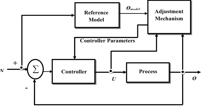
The technique adopted in this paper provides a systematic approach for automatically adjusting the control system in real time, so as to maintain a desire level of performance from the control system when the parameters of the plant dynamic model are not known and/or change in time. This technique is adaptive control, and to design and tuned a good controller, it is expected that the desired control system performance be specified, the dynamic model of the process to be controlled be known, and a suitable controller design method that will make it possible to realize the desired performance for the corresponding process model. The control loop is shown in Figure 3.
Figure 3. Configuration of the proposed system.
2.2.1. Controller Design
Several approaches such as Massachusetts Institute of Technology (MIT) rule, Lyapunov theory and augmented error theory can be employed to develop the adjusting mechanism. In this context, MIT rule will be used to develop a Model Reference Adaptive Control which combines a Proportional Integral and Derivative (MRAC PID) controller. To use the MIT rule, the equations for the error and cost function are presented as follows.
Let the difference between the actual output of the process and output of the referenced model be defined as the errore:
model
e= −θ θ (5)
The equation for the cost function θc is defined as:
2 1
( )
2 c
Jθ = e (6)
The cost function can be minimized such that the change in the parameter θc can be maintained in the direction of the negative gradient ofJ, and that is
c
c c
d J e
e dt
θ γ γ
θ θ
∂ ∂
= − = −
∂ ∂ (7)
The partial derivative expression ∂ ∂e θc is called the sensitivity derivative. It shows the change in error with respect to parameter θc. Equation (7) describes the change in the parameterθc with respect to time so as to be able to reduce the cost function to zero. γ representsa positive quantity which indicates the gain of the adaptation mechanism of the controller.
Now the transfer function of the HDD servomechanism is ( )
KG s whereKis a parameter whose value is unknown and ( )
G s is a second order system with a known transfer function (Equation 4). The objective is to design a controller such that the plant process could track a reference model whose transfer function, Gm( )s =K G so ( ), where Ko is a parameter whose value is known.
Definitions:
( ) ( ) ( ) o ( ) c( )
E s =KG s U s −K G s U s (8)
Controller Parameters Ɵ
∑
U N-
+
Controller Process
Adjustment Mechanism Reference
Model
Stating a control law:
( ) c c( )
U s = ×θ U s (9)
Substituting equation (9) into equation (8) and taking partial differential yields:
mod
( )
( ) c( ) el( )
c o
E s K
KG s U s s
K θ
θ
∂ = =
∂ (10)
Combining equation (7) and equation (10) yields
mod mod
c
el el
o
d K
e e
dt K
θ = −γ θ = −γ θΙ
(11)
Equation (10) provides the law for adjusting the parameter
c
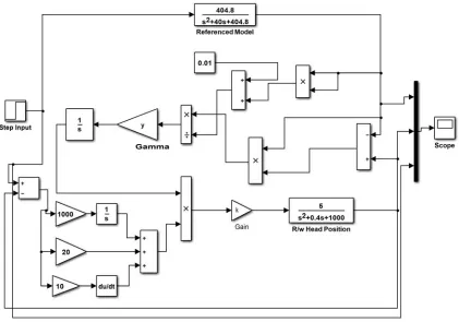
θ and the Simulink model of the control loop is shown in figure 4.
It is desired to generate the reference model. In order to do this, a second order transfer function is selected because the process under consideration is a second order system. Hence:
2
2 2
( )
2
m
n
n n
G s
s s
ω ζω ω =
+ + (12)
where ωn,
ζ
are the natural frequency response and the damping ratio of the system. They are obtained as follows:2
/ 1 p
M =e−πζ −ζ (13)
where Mp is the peak value which is equal to 0.06%.
Substituting this value into equation (13) gives the damp ratio
ζ
as 0.994. Equation (14) below defines the relationship between settling time Ts, the damp ratioζ
, and the natural frequency response, ωn.4
s n
T
ςω
= (14)
Substituting the value Ts =0.2s seconds and
ζ
=0.994into (14) gives the value for ωn as 20.12. Substituting these values into equation (12) yields
2
404.8 ( )
40 404.8
m
G s
s s
=
+ + (15)
2.2.2. Proportional Integral and Derivative (PID) Controller
The Matlab/Simulink block of the designed adaptive control system used for simulation in this context is shown in Figure 4. The parameters of the designed PID controller that is added to the control loop of the MRAC are presented in table 2.
Table 2. Parameters of PID.
Parameter Symbol Value
Proportional gain kp 20
Integral gain ki 1000
Differential gain kd 10
3. Results and Discussion
3.1. Results
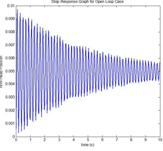
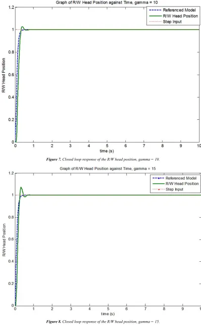
Simulations are performed in this context for both open loop and closed loop using Matlab software. Simulations are performed in Matlab/Simulink environment. The results obtained from the simulations are presented in Figures 5, 6, 7, 8 and 9.
Figure 5. Open loop response of the R/W head position.
Figure 7. Closed loop response of the R/W head position, gamma = 10.
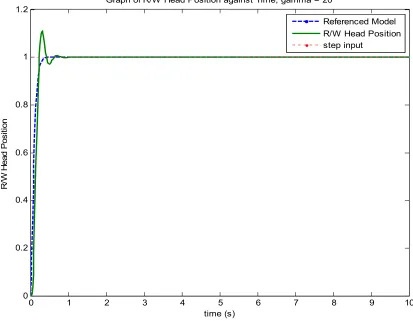
Figure 9. Closed loop response of the R/W head position, gamma = 20.
3.2. Discussion
In this paper a robust model reference adaptive controller (MRAC) which combines proportional integral and derivative control (PID) algorithm has been developed to give the so called MRAC PID controller. The developed controller is integrated with dynamic process of read/write (R/W) head position a head disk drive.
In Figure 5, the step response of the open loop showed that the system has significant. This cycling is undesirable as the positioning of the read/write (R/W) head of a hard disk drive (HDD) on appropriate track can be greatly affected.
The essence of the controller in the loop is to ensure that the R/W head is positioned so as to maintain the appropriate track at the exact time during HDD operation. Hence, the designed MRAC PID controller was able to take care of the cycling and improve the transient response of the R/W head position of HDD as shown in Figures 6, 7, 8, and 9 for different adaptive gains. The system dynamic behaviour in continuous time domain parameters for different values of adaptive gain (gamma), γ . It can be seen that as the values of gamma increases from 5 through 20, the system transient responses become fast with high overshoots. The system responses (R/W Head position) are appreciably improved within the range of adaptive gains chosen. Beyond this range, the system transient response performance could be subjected to such a large overshoot level such that it becomes unsatisfactory.
4. Conclusion
A MRAC which combines PID algorithm to give the so called MRAC PID controller has been presented in this paper. The objective is to develop a controller that will improve the continuous time response performance of a R/W head positioning system of a HDD for different adaptive gains by tracking a referenced input. This will ensure an appropriate positioning of R/W head when the computer system is operating.
The design specifications for establishing the performance of the system that were considered are the overshoot, settling time and damping ratio. The results obtained from the Simulations performed in this context, showed that the objective of the paper was realized.
References
[1] Uwe B. Raymond A. D. and Frank E. T., “Modeling and Control of a Dual Stage Actuator Hard Disk Drive,” Journal of Advanced Mechanical Design, System, and Manufacturing, Vol. 4, No 1, 2010.
[2] Teck B. G., Zhongming L. and Ben M. C, “Design and Implementation of a Hard Disk Drive Servo System Using Robust and Perfect Tracking Approach,” IEEE Transaction on Control Systems Technology, Vol.9, No. 2, March 2001.
0 1 2 3 4 5 6 7 8 9 10
0 0.2 0.4 0.6 0.8 1 1.2
time (s)
R
/W
H
e
a
d
P
o
s
it
io
n
Graph of R/W Head Position against Time, gamma = 20
[3] Basic of Computer and Hardware tips: tipsofbasiccomputer.blogspot.com
[4] MSC Laboratory: “Hard Disk Drive Control,” http://msc.berkeley.edu/research/disk.html
[5] Somyot K. and Amar N., “Design and Implementation of a High Performance Hard Disk Drive Servo Controller Using GA Based 2DOF Robust Controller,” International Journal of Innovative Computing, Information and Control, Vol. 8 No. 2, February 2012, ISSN 1349-4198,pp. 1025-1056.
[6] Christian C. M., Afred E. O and Chimezirim O. A., “Compensator for Optimum Hard Disk Read/write Head Positioning and Control,” International Journal of Scientific and Engineering Research, Vol. 6, Issue 3, March-2015, ISSN 2229-5518.
[7] Math Works: “Design Hard Disk Read/Write Head
Controller,” http://www.mathworks.com/help/control/ug/hard-disk-readwrite-head-controller. html
[8] Rahman M. A, Mamun A. A. and Yao K., “Design of Resonant Controller for Hard Disk Drive Servo System Using a Mixed Passivity and Small-gain Approach,” 8th International Conference on Electrical and Computer Engineering, Dhaka, 2014, pp.477-480.
[9] Mohammad H. F., Fardoon S. and Sayyed H. A., “Hard Disk Drive Mechanism Vibration Damping Using Disturbance Observer,” Universal Journal of Control and Automation 2(4): 77-83, 2014, DOI: 10.13189/ujca.2014.020402.
![Figure 1. A typical diagram of a hard disk drive [3].](https://thumb-us.123doks.com/thumbv2/123dok_us/9911958.1978622/3.595.117.479.84.398/figure-typical-diagram-hard-disk-drive.webp)