Vol.7 (2017) No. 2
ISSN: 2088-5334
Evaluation of the Pre-Cracked RC Beams Repaired with Sealant
Injection Method
Zaidir
#, Rendy Thamrin
#, Erick Dalmantias
##
Civil Engineering Department, Faculty of Engineering, Andalas University, Padang, 25163, Indonesia E-mail: [email protected], [email protected], [email protected]
Abstract—This paper presents an experimental study on the pre-cracked reinforced concrete beams repaired with sealant injection method. The purpose of this study is to evaluate the flexural and shear capacity of the repaired beams. Due to this purpose, totally six beams consisting of three beams for flexural and three beams for shear investigation were prepared and tested. Two beams indentified as control specimens were tested until failure, while the others were pre loaded until 50% and 90% of yield load (in case of flexural) and ultimate load (in the case of shear). The cracks in pre-cracked beams were injected with sealant injection method at selected locations. Then, after 24 hours the repaired beams were again tested until failure. Test results showed that stiffness of the beams after pre load is slightly increased compare to that initial specimen. In addition, the flexural and shear capacity of the repaired beams slightly increase compare to that control specimens.
Keywords— reinforced concrete beam; repair; pre-cracked; flexural capacity; shear capacity; sealant injection method
I. INTRODUCTION
The deterioration phenomenon of reinforced concrete structures due to seismic force is usually accompanied by structural cracks of concrete. Hence, there is need to recover the ability of an existing damaged structure using available repairing method. Repairing of concrete structures is a restoration of the deteriorated structure to improve the damaged condition of the original strength. One of the most popular available techniques is epoxy resins injection.
Reference [1] reported that the application of epoxy resins to repair and strengthen existing damage structures had been adopted both in research and practice due to its better mechanical properties and relatively easy to use. He also stated that reinforced concrete members repaired with an epoxy resin are found to develop flexural yield strength higher than the original specimens.
Another report presented an experimental and analytical study carried out to investigate the behavior of repaired cyclically loaded shearwalls [2]. It is observed from their study that heavily damaged shear wall can be successfully repaired with the almost total restoration of strength.
Bonding characteristics of epoxy mortar to repair concrete cracks were investigated by Kan et al. [3]. The test results obtained from their study confirmed that concrete specimens with a flexural crack have a higher repairing effectiveness than that with a shearing crack when repaired with epoxy mortar.
Two resin infiltration techniques were evaluated in an experimental study [4]. Two methods presented in their report are the injection and the gravity-feed techniques. It is reported that both of these techniques show comparable results.
Reference [5] investigated the deep of penetration of injection material in the open cut specimens. It is reported that resin infiltration can reach the steel reinforcement and was able to fill all the cracks even with the smallest crack widths of 0.01 mm.
Reference [6] investigated the cost-effective and user-friendly methods of repair with the application of synthetic epoxies and cement grout by injection in cracked concrete. The results indicated that epoxies for injection are effective and the load carrying capacity can be completely or partially restored in case of minor to moderately damaged beams. A considerable enhancement in the load carrying capacity and reduction in deflection were observed due to the injection of epoxy of RC beams was also reported [7]. Reference [8] investigated the behavior of normal and reactive powder concrete beams repaired with epoxy resin and reported that the epoxy injection technique could restore the original strength and delayed the appearance of the first crack.
this study is to investigate experimentally the flexural and shear capacity of reinforced concrete beams repaired with sealant injection method.
II. THE MATERIAL AND METHOD
A. Experimental Study
Six simply supported reinforced concrete beams, consisting of three beams for flexural (BF type) and three beams for shear (BS type) investigation were prepared and tested.
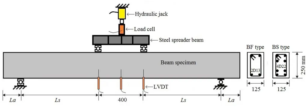
The beam cross section for both types of cross section has dimensions of 125 mm width and 250 mm height. The bottom and side concrete covers were 30 mm and 20 mm, respectively.
The shear span lengths (Ls) were 800 mm for BF type and 600 mm for BS type. The end anchorage lengths beyond the support (La) were 150 mm for BF type and 250 mm for BS type. For all of the beams, the distance between two point loads was 400 mm.
The beams were loaded until failure and pre-cracked load with two point loads using a 500 kN capacity hydraulic jack. The load from hydraulic jack was distributed into two equal points load using a steel spreader beam.
The level of load produced by the hydraulic jack was measured using a load cell placed the top surface of the spreader beam. Three displacement transducers placed at mid-span and at loading points were used to measure the deflection of the beams. All of the equipment used were connected to a data logger to record the data.
Fig. 1 and Table 1 show a schematic view of experimental set-up, dimension, equipment used, and beam cross section for each type of investigation purposes.
Longitudinal reinforcement for BF type was deformed steel bars with 13 mm diameter and 394 MPa yield strength, and for BS type was deformed steel bars with 22 mm diameter and 358 MPa yield strength. The stirrups used was deformed steel bars with 10 mm diameter and 389 MPa yield strength.
Fig. 1 Schematic view of test arrangement, beam dimension, equipment used, and beam cross sections
TABLEI BEAMS DATA AND CAPACITY
Calculated Calculated Vy or Exp. Pre-crack
Specimens fc' bw h d La Ls Ls/d ρρρρ (%) Vc Vf Vu Vmax Load, Vpc
(MPa) (mm) (mm) (mm) (mm) (mm) (kN) (kN) (kN) (kN) (kN)
BF-C 23.7 125 250 214 150 800 3.7 1.0 21.65 23.3 20.6 26.0
-BF-01 23.7 125 250 214 150 800 3.7 1.0 21.65 23.3 - - 10.3
BF-02 23.7 125 250 214 150 800 3.7 1.0 21.65 23.3 - - 18.5
BS-C 23.7 125 250 209 250 600 2.9 5.8 21.20 145.8 81.7 81.7
-BS-01 23.7 125 250 209 250 600 2.9 5.8 21.20 145.8 - - 40.9
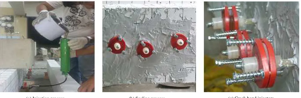
(a) Injection process (b) Sealing process (c) Crack bond injectors
Fig. 2 The process of sealant injection method
The ready mix concrete company was ordered to supply fresh concrete with the maximum aggregate size of 10 mm and the target compressive strength of 30 MPa. The compression strength of the concrete was obtained using the compression test of ten 150 x 300 mm concrete cylinders after 28 days of the casting day. The average concrete compressive strength obtained from compression tests was 23.74 MPa.
The cracks were repaired by epoxy resin with low and constant injection pressure named sealant injection method [9]. The system of sealant injection method used was consisted of crack bond injector (consists of injecting nozzle, push plates, plug, spring, nut, and bolt), AOI grout No. 1 and No. 2 being the injection materials (epoxy resin base), and EPO BOND EP-3 being the sealing material (epoxy resin base). The procedure for repairing a crack includes: surface preparation, seal crack at surfaces, installation of the crack bond injector, injecting AOI grout, and remove the sealing material. The photographs showing the process are shown in Fig. 2.
B. Analytical Study
A numerical model based on theoretical moment-curvature determination [10] was applied in this study. In this method, the cross section of the reinforced concrete is divided into a finite number of concrete and reinforcement layers. This method was implemented using the computer program Reinforced Concrete Cross Section Analysis (RCCSA) with a user-friendly interface to facilitate input of data and display of results [11]. The stress-strain relationship of concrete in compression used in this study is adopted from literature [12]. The value of maximum concrete compression strain is assumed to be 0.005. The stress-strain relationship of concrete in tension used is linear up to the tensile strength without tension stiffening. The tensile strength of concrete is taken as 10% of the concrete
compressive strength. The stress-strain model for steel bars employed in this study is a bi-linear model. Rupture strain of longitudinal reinforcement is taken as 0.05. An analytical load-deflection relationship is obtained from moment-curvature distribution.
III.RESULTS AND DISCUSSION
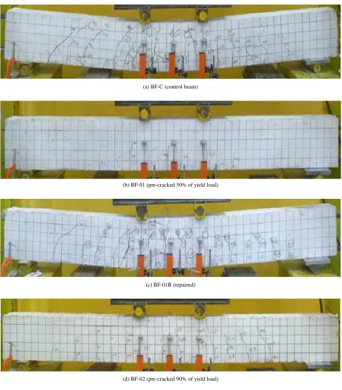
The maximum flexural capacity of control specimen of BF type (BF-C) observed from the test was 26 kN with the yield load of 20.6 kN. The BF-C beam failed in flexural failure modes as indicated by crushing of concrete on the top surface of the compression zone. The next two beams of BF type (BF-01 and BF-02) were loaded until the pre-cracked loads of 10.3 kN and 18.5 kN, respectively. The cracks were then repaired by epoxy resin with low and constant injection pressure. Then, after 24 hours the repaired beams were again tested until failure. Typical crack patterns of BF type are shown in Fig. 3.
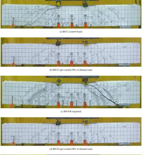
The same procedure was applied to BS type beams. The ultimate load of BS-C beam obtained from the test was 81.7 kN. The BS-C beam failed in shear with dominant shear cracks developed in the shear span zone. Then, BS-01 and BS-02 were loaded until the pre-cracked loads of 40.9 kN and 73.5 kN, respectively. Fig. 4 shows typical crack patterns of BS type. It is also confirmed from Fig. 4 that the diagonal shear cracks significantly develop in the shear span zone for all of the BS types.
(a) BF-C (control beam)
(b) BF-01 (pre-cracked 50% of yield load)
(c) BF-01R (repaired)
(d) BF-02 (pre-cracked 90% of yield load)
(e) BF-02R (repaired)
(a) BS-C (control beam)
(b) BS-01 (pre-cracked 50% of ultimate load)
(c) BS-01R (repaired)
(d) BS-02 (pre-cracked 90% of ultimate load)
(e) BS-02R (repaired)
Fig. 5 and Fig. 6 show the experimental load-deflection curves of the tested beams. Analytical prediction obtained using RCCSA software is also presented in these figures to show the flexural capacity and full flexural response for both type of the tested beams (BF and BS). Load-deflection curve of the pre-cracked beam (BF-01) is illustrated with a red line in Fig. 5(a). This beam was pre-loaded until 50% of the yield load. The cracks in pre-cracked beam were injected with sealant injection method at selected crack locations. Then, after 24 hours the repaired beam was again tested until failure. It is shown from Fig. 5(a) that the stiffness and capacity of the BF-01R beam after pre-cracked and repaired is slightly increased compare to that control specimen (BF-C).
Fig. 5(b) shows cracked beam (BF-02) that was pre-loaded until 90% of the yield load. It is also shown from Fig. 5(b) that the stiffness and capacity of the BF-02R are slightly increased compare to that control specimen.
Fig. 6 shows BS type beams that were tested to evaluate the shear capacity of the repaired beams. The red dash line
plotted in Fig. 6(a) and (b) specify the shear capacity provided by concrete, Vc. This value (Vc) was calculated using equation adopted from SNI 2847:2013 code [13]. It is shown from Fig. 6 that pre-crack loads for BS type are higher than Vc to make sure that the diagonal cracks previously developed before the repairing process as expected in this study
The pre-cracked beam (BS-01) was preloaded until 50% of the ultimate load and illustrates with a red line in Fig. 6(a). Then, the pre-cracked beam was injected with sealant injection method at locations of the shear crack. The repaired beams were again tested until shear failure. It is shown from Fig. 6(a) that the capacity of the BS-01R beam after pre-cracked and repaired is slightly increased compare to that control specimen (BS-C).
Fig. 6(b) shows BS-02 beam that was pre-loaded until 90% of the ultimate load. It is also shown from Fig. 6(b) that the capacity of the BF-02R is slightly increased compare to that control specimen.
0 5 10 15 20 25 30
0 10 20 30 40 50 60
S h e a r F o rc e ( k N ) Deflection (mm)
BF-C BF-01 BF-01R
(a) 0 5 10 15 20 25 30
0 10 20 30 40 50 60
S h e a r F o rc e ( k N ) Deflection (mm)
BF-C BF-02 BF-02R
(b) 0 5 10 15 20 25 30
0 10 20 30 40 50 60
S h e a r F o rc e ( k N ) Deflection (mm)
BF-C Flex. Capacity
(c)
Fig. 5 Experimental and analytical load-deflection curves of BF type
0 20 40 60 80 100 120 140 160
0 5 10 15 20 25 30 35
S h e a r F o rc e ( k N ) Deflection (mm)
BS-C BS-01 BS-01R Vc
(a) 0 20 40 60 80 100 120 140 160
0 5 10 15 20 25 30 35
S h e a r F o rc e ( k N ) Deflection (mm)
BS-C BS-02 BS-02R Vc
(b) 0 20 40 60 80 100 120 140 160
0 5 10 15 20 25 30 35
S h e a r F o rc e ( k N ) Deflection (mm)
BS-C Flex. Capacity
(c)
IV.CONCLUSIONS
Six simply supported reinforced concrete beams were tested to evaluate the flexural and shear capacity of the repaired beams and the following conclusions are drawn: The injection of epoxy resin was effective in restoring the strength of the damaged beam. The stiffness of the BF beams after pre-cracked is slightly increased compare to that control specimen. The flexural and shear capacity of the repaired beams are slightly increased compare to that control specimen. Analytical flexural response before and after yielding of tensile reinforcement obtained using RCCSA software compares well with the test result.
ACKNOWLEDGMENT
This study was financially supported by Hibah Klaster
Riset Guru Besar financial year 2016, with contract number
103/UN.16/HKRGB/LPPM/2016.
REFERENCES
[1] Tasai A., Resistance of flexural reinforced concrete members after repair with epoxy resin, Proc. of Ninth World Conference on
Earthquake Engineering, Japan, VII (1988), pp. 359-364.
[2] Vecchio FJ, Haro de la Pena OA, Bucci F, Palermo D., “ Behavior of repaired cyclically loaded shearwalls”, ACI Structural Journal, 99(3), (2002), pp. 327-334.
[3] Kan YC, Yen T, Lee MG., “Restored Strength of Cracked Concrete Beam Repaired by Epoxy and Polymethyl Methacrylate”, ACI
Materials Journal, 105 (5), (2008) 451-458.
[4] Felicetti R, De Domenico VH., “ Cracked concrete repair with epoxy-resin infiltration”, Proc. of Concrete Repair, Rehabilitation and
Retrofitting II – Alexander et al (eds), (2009), pp. 783-789.
[5] Borosnyói A, Snóbli I., “Crack width variation within the concrete cover of reinforced concrete members”, Materials Technology, 62(3) (2010), pp. 70–74.
[6] Anwar Shah, Qaisar Ali , Basir Alam , Khan Shahzada and Arsalan Khan, “Study on Performance Evaluation of Adhesive used for Cracks Injection in Concrete”, International Journal of Advanced Structures and Geotechnical Engineering, Vol. 01, pp.29-32, No. 01, 2012.
[7] Saeed Ahmad, Ayub Elahi, Salim Barbhuiya, Yaqub Farooqi, “ Repair of Crack in Simply Supported Beams using Epoxy Injection”, Material
and Structures, 46(9), Sept. 2013.
[8] Aamer Najim Abbas, Ali Sabah Ahmed, Saad Khalaf Mohaisen, “ Rehabilitation of Normal and Reactive Powder Reinforced Concrete Beams using Epoxy Injection Technique “, International Journal of
Civil Engineering and Technology (IJCIET), Vol.7, pp. 31-42, 2016.
[9] Matsufuru T. AOI Chemical Inc., Japan. U.S. Patent 4986862, Jan 22 (1991).
[10] Park R, Paulay T., Reinforced Concrete Structures. John Wiley, New York, (1975).
[11] Thamrin R, Reinforced Concrete Cross Section Analysis (RCCSA) V4.3, Jurusan Teknik Sipil, Fakultas Teknik, Universitas Andalas, (2014). [12] Almusallam TH, Alsayed SH., ”Stress-Strain Relationship of Normal,
High Strength and Light Weight Concrete”, Magazine of Concrete
Research, 47(170) (1995), pp. 39-44.
[13] SNI 2847:2013, “Persyaratan beton struktural untuk bangunan gedung”,