−
Finite Element Analysis of a New Specimen for
Conduct-ing Fracture Tests under Mixed Mode I/III LoadConduct-ing
S. Pirmohammad
∗, A. Bayat
Mechanical Engineering Department, Faculty of Engineering, University of Mohaghegh Ardabili, Ardabil, Iran.
Article info
Article history:
Received 2016.06.10 Received in revised form 2016.08.22
Accepted 2016.08.31
Keywords:
Mixed mode I/III Cracked disc specimen Fracture strength Asphalt concrete
Abstract
In this paper, a new disc-shaped specimen containing a tilted crack was proposed so as to conduct fracture tests under mixed mode I/III loading. This specimen was able to produce complete mode mixities, ranging from pure mode I to pure mode III. Many finite element analyses were performed to obtain crack parameters (i.e. stress intensity factors at the crack tip) and geometry factors. It was shown that the mode III was added to the mode I loading as the crack angle changed. Moreover, the crack length as well as position of the lower supports was varied to study loading type at the crack tip. Finally, applicability of the proposed specimen in experimental point of view was considered by performing fracture experiments on the asphalt concrete. The results showed that fracture strength of the asphalt concrete decreases as the proportion of mode III at the crack tip enhances.
1. Introduction
The cracked parts are generally subjected to combi-nations of mode I (opening mode), mode II (in-plane shear mode), and mode III (out-of-plane shear mode) loading. Many investigations have been performed in the past on the mixed mode fracture of the brittle or quasi-brittle materials (see e.g. [1-5]). Nevertheless, most of these investigations have been focused on the mixed mode I/II loading, and some specimens such as SENB (single notched beam) [6-7], SCB (semi-circular bend) [8-9], BD (Brazilian disc) [10-11] etc. have been proposed by the researchers. Moreover, mixed mode I/II fracture has been studied either theoretically uti-lizing various fracture criteria (see [12-14]) or experi-mentally using fracture tests. Conducting experiments are often very expensive, so the researchers prefer to do these on laboratory specimens. These specimens should be able to simulate the same states of stresses around the crack tip as those of the real cracked parts under service conditions. However, there exist some en-gineering components that the mixed mode I/III load-ing occurs at the crack tip. For instance, cracks in
the road structures and automotive axles are some to mention. Based on the recent investigations made by Ameri et al. [15] and Ayatollahi et al. [16], vehicle traf-fic causes a crack tip available in asphalt pavements to experience not only opening mode (mode I loading) but also tearing mode (mode III loading).
On the other hand, relatively few tasks can be found in literature on the mixed mode I/III loading. Lack of suitable specimens (being able to create full spec-trum of mixed mode I/III loading) and simple fixture for loading may be the main reason. A suitable spec-imen should have simple configuration, cost-effective specimen preparation, easy testing set-up, and also ca-pability of simulating complete mode mixities, ranging from pure mode I to pure mode III. Pook [17] studied mixed mode I/III fatigue crack growth behavior of mild steel using SENB specimen containing a tilted crack. Li and Qian [18] investigated mixed mode I/III fatigue fracture of steel utilizing compact tension (CT) speci-men. In another study, Feng et al. [19] studied mixed mode I/III fracture toughness of aluminum alloys by means of a modified CT specimen. It is noticed that all the aforementioned specimens can only produce lim-∗Corresponding author: S. Pirmohammad (Assistant professor)
E-mail address: s [email protected]
ited mixed mode I/III i.e. they are unable to simulate larger mode III and particularly pure mode III loading. Mode III loading may affect the mixed mode I/III frac-ture behavior of different materials differently. For brittle materials like 1.25% C bainitic steel, the frac-ture toughness increases as mode III at the crack tip in-creases. For ductile materials like 2034 type aluminum alloys, fracture toughness declines by increasing pro-portion of mode III. However, in some ductile materi-als like spheroid zed steel, the fracture toughness re-mains approximately unchanged by varying mode III [20]. Therefore, based on the previous experimental in-vestigations, one can say that no single trend has been observed as for the effect of mode III loading on frac-ture behavior of the materials [21].
In this paper, the numerical analysis of a new frac-ture test configuration was considered for performing fracture tests under pure mode I, pure mode III and mixed mode I/III loading using finite element code ABAQUS. A simple three-point bend fixture was used for loading the proposed test specimen. Moreover, the effect of mode III on fracture behavior of asphalt con-crete was investigated at a sub-zero temperature.
2. Material and Method
A disc-shaped specimen containing an inclined crack was proposed in this paper for creating pure mode I, pure mode III, and combinations of mode I and mode III. Fig. 1 shows the suggested geometry. In this spec-imen, the crack was normal to the circular plane of the specimen. The parameters a, R, and t were crack length, radius and thickness of the specimen, respec-tively. This specimen was compressively loaded by a simple three-point fixture. Moreover,S, L, l and were defined as lower supports distance from the load line, length of the lower supports, the distance between one end of the supports and the center line of the specimen and angle of the crack, respectively.
Fig. 1. Disc shaped specimen, (a) Isometric view (b) Bottom view.
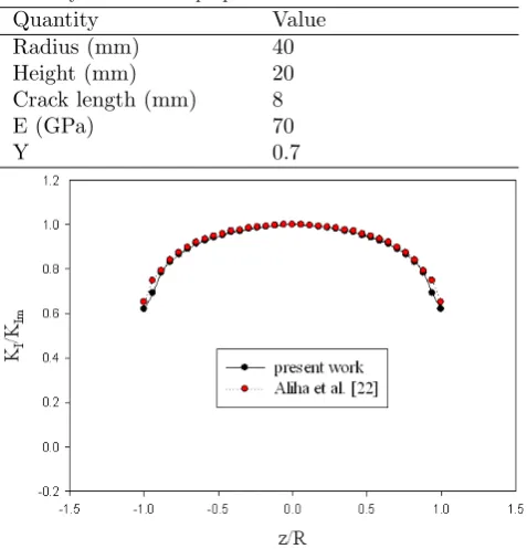
To validate the finite element models for deter-mining the stress intensity factors at the crack front, the cylindrical specimen analyzed by Aliha et al. [22] was chosen. The geometrical dimensions and material properties of the specimen used by them are listed in
Table 1. Mode I stress intensity factors (KI) at the
crack front of this specimen calculated by Aliha et al. [22] together with the results of the model built in the present work are given in Fig. 2. Meanwhile, the pa-rameter of mode I stress intensity factors presented in Fig. 2 was normalized byKIm representing theKI at
the middle point of crack front. As is clear from Fig. 2, the finite element results extracted from ABAQUS were well-matched with those of Aliha et al. [22].
Table 1
Geometry and material properties.
Quantity Value
Radius (mm) 40
Height (mm) 20
Crack length (mm) 8
E (GPa) 70
Y 0.7
Fig. 2. Comparison of the FE results for the cylindri-cal specimen.
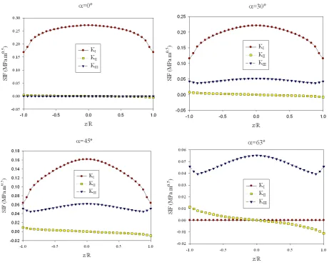
dis-tribution of stress intensity factors) through the crack front of the proposed specimen for various crack orien-tations. The parameterz/R describes the crack front locations. For example, the parametersz/R = 0 and z/R=±1 refer to the middle-point and end points at the crack front, respectively. As can be seen in Fig. 4, all modes of I, II and III are observed at the crack front. It is seen that the value ofKI is maximum at the
mid-dle point (z/R= 0), and its value decreases as one goes far from middle of the specimen. Moreover, the value ofKI for all the crack front locations decreases as the
crack angle increases , thus its value for the crack angle α= 63◦falls to zero at entire crack front. The value of KII at the middle point is zero for all crack angles, and
its value increases as one move toward the end points along the crack front. On the other hand, the value of KIII is maximum at the middle point, and its value
declines as one goes far from middle of the specimen similar to the results observed forKI. Therefore, from
the results shown in Fig. 4, it can be deduced that the specimen experiences pure mode I as the crack angle is zeroα= 0◦, and pure mode III loading is achieved as the crack rotates to reachα= 63◦. While, mixed mode I/III is observed for other crack angles betweenα= 0◦ andα= 63◦. Hence, the proposed specimen can pro-duce all combinations of mixed mode I and mode III by simply changing the crack angle value.
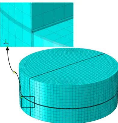
Fig. 3. Finite element model together with closer view of the elements near the crack front.
3. Results and Discussion
3.1. Finite Element Analysis and Discussions
The stress intensity factors, KI and KIII directly
ex-tracted from the ABAQUS were put into the following equations to find mode I and mode III geometry fac-tors,YI andYIII, respectively.
YI = KI √
πa Rt2
6P S (1a)
Ym= Km √
πa Rt2
6P S (1b)
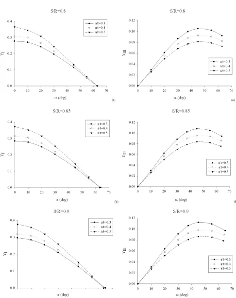
Variations of geometry factors (YI and YIII) against
the crack angle for different values of span ratiosS/R and crack length ratios a/t are plotted in Figs. 5-6. From which, it is seen that when the crack angle is α= 0◦, the disc-shaped specimen is subjected to pure mode I. Whereas, by increasing the crack angle, mode III component is added to mode I at the crack tip i.e. the specimen is subjected to mixed mode I and mode III. In addition, as the crack angle increases, the mode III component increases at the crack tip, while the mode I component decreases, so the specimen is loaded under pure mode III at the crack anglesα= 63◦−65◦ depending on the crack length (a/t) and position of the supports (S/R). As is seen from Figs. 5-6, the values of YI increases while those ofYIII decreases as the crack
length increases. Also, the pure mode III is reachable by the considered specimen for different values ofS/R shown in Fig. 6. It is noted that the values of geom-etry factors (YI and YIII) are required for computing
fracture toughness of any material.
Fig. 4. Stress intensity factors (SIFs) through the crack front of the specimen.
It was noticed that Aliha et al. [22,24] had re-cently suggested a similar specimen to simulate mixed mode I/III loading at the crack front. Indeed, this specimen had disc-shaped geometry containing a tilted crack similar to the one shown in Fig. 1. Nevertheless, the lower supports in this specimen located on the en-tire bottom of specimen. This specimen was improved in the present work due to incorrect failure at the lower supports for the asphalt concretes, such that the lower supports did not touch the specimen bottom entirely as shown in Fig. 1.
3.2. Fracture Test Results and Discussion
In the previous section, finite element results on the disc-shaped specimen were given for different crack lengths (a/t) and span ratios (S/R). Nevertheless, the proposed specimen was required to be explored in practicability point of view to ensure that works ap-propriately for conducting fracture experiments. For this purpose, several disc-shaped specimens made of asphalt concrete were prepared, and were then tested. As mentioned above, asphalt concrete as a brittle
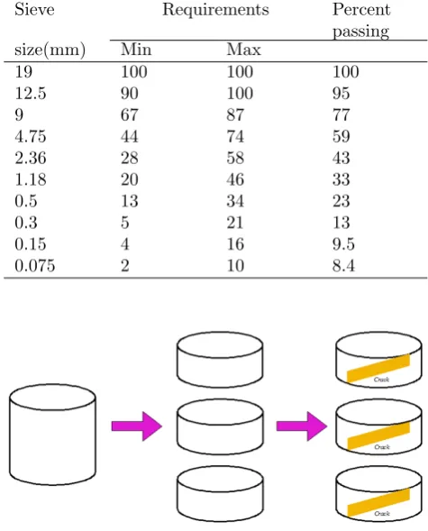
material was selected for conducting the fracture tests. The aggregate gradation of this mixture is given in Ta-ble 2. This type of aggregate gradation is known as No. 4, and was provided based on the Superpave mix design developed by the Iran Highway Asphalt Paving Code (IHAPC). Nominal maximum aggregate size (NMAS) for this mixture is 19mm. The binder with penetra-tion grade of 60-70, frequently used in the Iran road networks, is employed in the asphalt concrete prepa-ration. Moreover, air void content of the mixture is 4%.
Fig. 5. Mode I geometry factors for different crack lengths and loading conditions of (a) S/R = 0.8 (b) S/R= 0.85 (c) S/R= 0.9.
Table 2
Aggregate gradation No. 4 used in the sample preparation.
Sieve Requirements Percent
passing
size(mm) Min Max
19 100 100 100
12.5 90 100 95
9 67 87 77
4.75 44 74 59
2.36 28 58 43
1.18 20 46 33
0.5 13 34 23
0.3 5 21 13
0.15 4 16 9.5
0.075 2 10 8.4
Fig. 7. Process of producing cracked disc specimen from cylindrical samples.
The fracture tests were planned to be performed under several loading modes of pure mode I (α= 0◦), pure mode III (α = 63◦), and two mixed mode I/III (α= 30◦ and α= 63◦) at a sub-zero temperature of −20◦C. As discussed earlier, the minimum span ratio (namelyS/R= 0.8) was selected to conduct the exper-iments for avoiding inappropriate failure of the speci-mens at the region near the lower supports. In order to enhance accuracy of the fracture test results, four specimens were provided for each case. The produced specimens were kept in a freezer fixed at a tempera-ture of −20◦C for 4 hours. These cooled specimens were located in the fracture test set-up shown in Fig. 8, and then were compressively loaded with a constant displacement rate of 3 mm/min. Fig. 9 shows a typi-cal force-displacement curve recorded from the fracture tests. As is clear from Fig. 9, the force increased lin-early to reach its maximum value called fracture load (Pcr), and then sharply decreased to zero. This figure indicates that a brittle fracture occurred in the spec-imens, thus linear elastic fracture mechanics (LEFM) concept can be applied for the tested asphalt concretes.
As mentioned above, the asphaltic materials behave as linear elastic at sub-zero temperatures; therefore, the stress distribution at the crack front can be de-scribed by stress intensity factors which are defined as
below for the mixed mode I/III loading:
KIf =
6SPcr Rt2 YI
√
πa (2a)
KIIIf =
6SP Rt2YIII
√
πa (2b)
where,KIfandKIIIf refer to the mode I and mode III
critical stress intensity factors, respectively. As men-tioned above, the fracture load (Pcr) is the maximum force available in the force-displacement curves (as dis-played in Fig. 9). YI and YIII are geometry factors
that were calculated from the numerical analyses as presented earlier. The critical stress intensity factors were finally calculated using the Eqs. 2 for each loading condition, and are given in Table 3.
Table 3
Aggregate gradation No. 4 used in the sample preparation. Loading mode No. KIf(M P a.0.5) KIIIf(M P a.0.5)
Pure mode I 1 0.80 0
(α= 0◦) 2 0.86 0
3 0.71 0
4 0.80 0
Mixed mode I/III 1 0.60 0.21
(α= 30◦) 2 0.75 0.27
3 0.64 0.23
4 0.75 0.27
Mixed mode I/III 1 0.58 0.45
(α= 30◦) 2 0.53 0.41
3 0.56 0.43
4 0.57 0.44
Pure mode III 1 0 0.53
(α= 63◦) 2 0 0.57
3 0 0.61
4 0 0.57
The averaged values of effective critical stress in-tensity factor Keff are presented in Fig. 10. Parameter of the effective critical stress intensity factor (Kef f) is
defined as below:
Kef f= √
K2
If+K
2
IIIf (3)
where, Kef f reduces to KIf and KIIIf when the
specimen is subjected to pure mode I and pure mode III loading, respectively. It is well-known thatKef f is
the main fracture parameter stating the material resis-tance against brittle fracture under mixed mode load-ing conditions. As is clear from Fig. 10, by addition of the mode III to mode I at the crack front, fracture resistance of the asphalt concrete was reduced. Hence, presence of mode III at the crack front can significantly decrease fracture strength of the asphaltic materials. Based on the investigations carried out by Ameri et al. [15] and Ayatollahi et al. [16] on the cracked road, mode III loading was found to be a serious threat for the crack growth. Hence, effect of mode III on the fracture of asphaltic materials must be regarded in de-signing road structures.
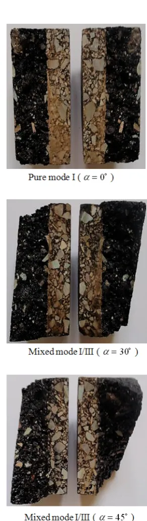
leads to multiple fracture planes intersecting the crack front. Therefore, the fracture surface often found to be non-planar in mixed mode I/III fracture as is clearly seen in Fig. 11. Twisted fracture trajectory due to presence of mode III at the crack front is observed from considering fracture surface of the specimens shown in Fig. 11.
Fig. 8. Fracture test set-up for conducting mixed mode I/III experiments.
Fig. 9. A typical force-displacement curve recorded from the fracture tests.
Fig. 10. Effective critical SIF for different loading modes.
In order to verify the fracture results presented above, the results for mode I loading was compared with those of Ameri et al. [25] and Ayatollahi and Pir-mohammad [1]; mode I fracture toughness of asphalt concretes was measured between 0.7 and 1 MPam0.5
dependent on the temperature conditions and mixture variety using a semi-circular bend (SCB) specimen. The mode I fracture toughness of 0.8 obtained in the present work with the aforementioned asphalt concrete specifications and temperature conditions was within the range measured by the mentioned researchers. This verifies that the specimen used in the present study can predict the fracture toughness of materials with a suit-able level of accuracy.
4. Conclusions
1. A new fracture test configuration was proposed using FE analysis for performing experiments un-der pure mode I, pure mode III and mixed mode I/III, loading. Moreover, many finite element analyses on this specimen were carried out to find geometry factors for different crack lengths (a/t) and span ratios (S/R).
2. Fracture tests were successfully performed on the asphalt concrete under different loading modes, namely pure mode I, pure mode III and two mixed mode I/III at a sub-zero temperature of −20◦C.
3. The fracture results displayed that by addition of the mode III to mode I at the crack front, frac-ture resistance of the asphalt concrete decreased.
4. Twisted fracture trajectory due to presence of the mode III at the crack front was observed from considering fracture surface of the specimens.
References
[1] S. Pirmohammad, M.R. Ayatollahi, Fracture resis-tance of asphalt concrete under different loading modes and temperature conditions, Constr. Build. Mater. 53 (2014) 235-242.
[2] M.R.M. Aliha, H. Behbahani, H. Fazaeli, M.H. Rezaifar, Study of characteristic specification on mixed mode fracture toughness of asphalt mixtures, Constr. Build. Mater. 54 (2014) 623-635.
[3] I. Artamendi, H. Al-Khalid, A comparision between beam and semi-circular bending fracture tests for asphalt, J. Road. Mater. Pavement. Des. 6 (2006) 163-180.
[4] J.R. Yates, R.A. Mohammed, Crack propagation under mixed mode (I+III) loading, Fatigue. Fract. Eng. M. 19 (1996) 1285-1290.
[5] V.E. Lazarus, J.B. Leblond, S.E. Mouchrif, Crack front rotation and segmentation in mixed mode I + III or I + II + III. Part II: Comparison with exper-iments, J. Mech. Phis. Solids. 41 (2001) 1421-1443.
[6] T. Fett, G. Gerteisen, S. Hahnenberger, G. Martin, D. Munz, Fracture tests for ceramics under mode-I, mode-II and mixed-mode loading, J. Eur. Ceram. Soc. 15 (1995) 307-312.
[7] G.S. Xeidakis, I.S. Samaras, D.A. Zacharopoulos, G.E. Papakalitakis, Crack growth in a mixed-mode loading on marble beams under three point bend-ing, Int. J. Fracture. 79 (1996) 197-208.
[8] K.P. Chong, M.D. Kuruppu, J.S. Kuszmual, Frac-ture toughness determination of layered materials, Eng. Fract. Mech. 28 (1987) 43-54.
[9] M.R. Ayatollahi, M.R.M. Aliha, M.M. Hasani, Mixed mode brittle fracture in PMMA - an ex-perimental study using SCB specimens, Mater. Sci. Eng. 417 (2006) 348-356.
[10] S.H. Chang, C.L. Lee, S. Jeon, Measurement of rock fracture toughness under modes I and II and mixed-mode conditions by using disc-type speci-men, Eng. Geol. 66 (2002) 79-97.
[11] M.R.M. Aliha, M.R. Ayatollahi, R. Ashtari, Mode I and mode II fracture toughness testing for a coarse grain marble, Appl. Mech. Mater. 5-6 (2006) 181-188.
[12] G.C. Sih, Strain-energy-density factor applied to mixed mode crack problems, Int. J. Fracture. 10 (1974) 305-321.
[13] M.A. Hussain, S.L. Pu, J. Underwood, Strain en-ergy release rate for a crack under combined mode I and mode II, Fracture analysis ASTM STP 560. Philadelphia: American Society for Testing and Materials, (1974) 2-28.
[14] M.R. Ayatollahi, H. Abbasi, Prediction of fracture using a strain based mechanism of crack growth, Build. Res. J. 49 (2001) 167-180.
[15] M. Ameri, A. Mansourian, M. Heidary Khavas, M.R.M. Aliha, M.R. Ayatollahi, Cracked asphalt pavement under traffic loading - A 3D finite element analysis, Eng. Fract. Mech. 78 (2011) 1817-1826.
[16] M.R. Ayatollahi, S. Pirmohammad, K. Sedighi-ani, Three-dimensional finite element modeling of a transverse top-down crack in asphalt concrete, Comput. Concrete. 13 (2014) 569-585.
[17] L.P. Pook, The fatigue crack direction and thresh-old behaviour of mild steel under mixed mode I and III loading, Int. J. Fatigue. 7 (1985) 21-30.
[18] H.F. Li, C.F. Qian, Experimental study of I + III mixed mode fatigue crack transformation propaga-tion, Fatigue. Fract. Eng. M. 34 (2011) 53-59.
[19] X. Feng, A.M. Kumar, J.P. Hirth, Mixed mode I/III fracture toughness of 2034 aluminum alloys, Acta. Metall. Mater. 41 (1993) 2755-2764.
[21] S.V. Kamat, M. Srinivas, R.P. Rama, Mixed mode I/III fracture toughness of Armco iron, Acta. Mater. 46 (1998) 4985-4992.
[22] M.R.M. Aliha, A. Bahmani, Sh. Akhondi, Numer-ical analysis of a new mixed mode I/III fracture test specimen, Eng. Fract. Mech. 134 (2015) 95-110.
[23] D. Tim, B. Birgisson, D. Newcomb, Development of mechanistic-empirical pavement design in Min-nesota, J. Tran. Res. Rec. 1629 (1998) 181-188.
[24] M.R.M. Aliha, A. Bahmani, Sh. Akhondi, A novel test specimen for investigating the mixed mode I+ III fracture toughness of hot mix asphalt com-positesExperimental and theoretical study, Int. J. Solids. Struct. 90 (2016) 167-177.