FULL PAPER
Tiangong-1’s accelerated self-spin
before reentry
Hou‑Yuan Lin
1,6, Ting‑Lei Zhu
1,6, Zhi‑Peng Liang
2,6, Chang‑Yin Zhao
1,6*, Dong Wei
1,6, Wei Zhang
1,6,
Xing‑Wei Han
2,6, Hai‑Feng Zhang
3,6, Zhi‑Bin Wei
4, Yu‑Qiang Li
5,6, Jian‑Ning Xiong
1,6, Jin‑Wei Zhan
1,6,
Chen Zhang
1,6, Yi‑Ding Ping
1,6, Qing‑Li Song
2,6, Hai‑Tao Zhang
2,6and Hua‑Rong Deng
3,6Abstract
The detection and study of the rotational motion of space debris, which is affected by environmental factors, is a popular topic. However, relevant research in extremely low‑orbit regions cannot be conducted due to a lack of observational data. Here, we fill in the gaps to present the rotational evolution of Tiangong‑1 in the 5 months prior to reentry. Derived from the changes in the relative distance of its two corner cube reflectors from satellite laser ranging data, the angular momentum of Tiangong‑1, which is relatively stable during observation, deviates from its maximum principal axis of inertia and precesses around the normal direction of the orbital plane due to gravity gradient torque at an angle of 23.1◦± 2.5◦ . Requiring consistency with the relationship between the angular momentum and preces‑
sion rate leads to a solution for the rotation rate, which is thus found to increase. This result cannot be explained by any previously developed torque models. Hence, an atmospheric density gradient torque (ADGT) model that consid‑ ers the torque generated by the change in atmospheric density with orbital altitude at the satellite scale is proposed to explain the rotational acceleration mechanism of extremely low‑orbit objects. The numerical results show that the ADGT model provides a non‑negligible ability to explain, but cannot fully describe, the acceleration effect. The data on the rotational evolution of Tiangong‑1 can provide an important basis for aerodynamic model improvement by addressing minor factors omitted in previous models.
Keywords: Tiangong‑1, Rotational state estimation, Space debris, SLR
© The Author(s) 2019. This article is distributed under the terms of the Creative Commons Attribution 4.0 International License (http://creat iveco mmons .org/licen ses/by/4.0/), which permits unrestricted use, distribution, and reproduction in any medium, provided you give appropriate credit to the original author(s) and the source, provide a link to the Creative Commons license, and indicate if changes were made.
Introduction
When the fourth artificial satellite in human history, Van-guard I, was launched in 1958, its rotational speed was found to decay exponentially with time, which was sug-gested to be the effect of eddy current torque (Wilson 1959; LaPaz and Wilson 1960). After decades of research, eddy current torque has been verified as the main dis-sipation factor that causes a decrease in spacecraft rota-tional speed (Smith 1962; Williams and Meadows 1978; Praly et al. 2012; Lin and Zhao 2015). However, some observations of individual rockets show that they have increasing rotational speed (Meeus 1971), and some satellites begin to spin after losing attitude control.
The causes of accelerated spin have not been clearly explained. Whether these phenomena are due to satellite fuel leaks (Boehnhardt et al. 1989), accidental collisions, or the continuous action of certain factors in space can-not be confirmed from scattered observations.
In recent years, the task of active debris removal has spurred the need for the detection of and research on the rotational state of space debris (Liou and Johnson 2009; Liou 2011; Bonnal et al. 2013; Deluca et al. 2013; Shan et al. 2016). Estimating the rotational state of space debris is very difficult when using ground-based observa-tions because of the limited detection capability and the small amount of acquired data. The existing detection and research results are limited to objects at orbital alti-tudes of approximately 500–1500 km or higher, and such objects are relatively easy to detect (Kucharski et al. 2013; Koshkin et al. 2016; Lin and Zhao 2018; Pittet et al. 2018). In the extremely low-orbit region (altitudes lower than
Open Access
*Correspondence: [email protected]
1 Purple Mountain Observatory, Chinese Academy of Sciences, Nanjing 210034, China
orbital lifetime require better observation conditions and higher observation capability. To date, comprehensive data on the rotational evolution of extremely low-orbit objects are unavailable, and the high-profile Tiangong-1 reentry event provided an excellent opportunity for data collection.
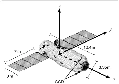
Tiangong-1, China’s first prototype space station, was launched in September 2011. After its service ended in March 2016, its orbital altitude gradually decreased, and the satellite reentered the atmosphere on April 2, 2018, at UTC 0:15. Tiangong-1 was equipped with two cor-ner cube reflectors (CCR), which can be used for satel-lite laser ranging (SLR), on the docking interface (Fig. 1). The SLR technique measures the round-trip time of laser pulses from the observatory to the satellite to calculate distance (Pearlman et al. 2002). Modern SLR systems can provide instantaneous range measurements at centim-eter-level precision, or even millimeter level for single shot, making these systems the most precise technique to track spacecraft in low Earth orbits (Tapley et al. 2004). We organized an optical and laser joint observation of Tiangong-1 from November 2017 (at an altitude lower than 300 km) to March 2018 and obtained 95 passes of
in combination with the dynamic model (Lin et al. 2016) and the relationship of all effective solutions, we obtain the rotational state of Tiangong-1 as well as the evolution thereof in the 5 months prior to reentry and fill in the gaps in the rotational evolution data on extremely low-orbit objects.
Methods
Processing of SLR data
The rotational state of Tiangong-1 can be determined by the changes in the relative distance P of its two CCRs
(Fig. 2). This change in distance is due to the combined effect of changes in the observation direction and the satellite attitude. As the larger CCR has multiple reflec-tors, the relative distance obtained is not necessarily the distance between the centers of the two CCRs. Hence, an additional distance factor δP , which is within ±0.15m
according to its size, is added to the calculation (see Eq. (3)) to correct the distance deviation. In addition, due to the limitations of the observation conditions, the data signals from the small CCR are not evenly distributed (Fig. 2), and the weights of the data need to be adjusted to ensure calculation accuracy.
Estimation of the orientation of angular momentum
The inertia ellipsoid of a rigid body can be established in the body-fixed coordinate system based on the principal moment of inertia Ix,Iy,Iz (Markeyev 2006), as shown
in Fig. 3. For a general case of torque-free rotational motion, the angular momentum and angular velocity (instantaneous rotational axis) on the inertia ellipsoid are not constants. The trajectory of the angular velocity is called the polhode. Define L=H2/2EIz , where H and E are the angular momentum magnitude and the kinetic
CCR
Fig. 1 Model of Tiangong‑1 and its body‑fixed coordinate system. The main body of Tiangong‑1 is 10.4 m in length with a maximum diameter of 3.35 m and a weight of 8.5 t. The two solar panels on either side of the satellite have dimensions of 7 m × 3 m. A body‑fixed coordinate system is established with the center of mass of the model as the origin O. The three coordinate axes are along the principal axes of inertia, where the Ox‑axis points along the minimum axis of inertia in the docking direction and the Oz‑axis follows the maximum axis of inertia. The principal moments of inertia are Ix=16,403.01 kg m2 , Iy=70,915.56 kg m2 , and Iz=76,392.38 kg m2 . The relative vector of the centers of the two corner cube reflectors on the docking interface (from the large one to the small one) can be expressed in the body‑fixed coordinate system as P0=(−0.2029, 0.6406, 2.6625)m
energy of self-spin, respectively. Then, L can indicate the position of the trajectory of the angular velocity and the angular momentum in the inertia ellipsoid. The polhode when L=Iy/Iz (the brown line in Fig. 3) divides the
iner-tia ellipsoid into four regions (Markeyev 2006), in which the polhode surrounds ±x or ±z . When L is equal to 1 and Ix/Iz , the axes of rotation coincide with the Oz- and Ox-axes, respectively. Because the magnitude of angular velocity is not constant in a polhode, when comparing the rotational speeds at different times, the equivalent rotational speed H/Iz can be used to characterize the
change in rotational speed due to external torque.
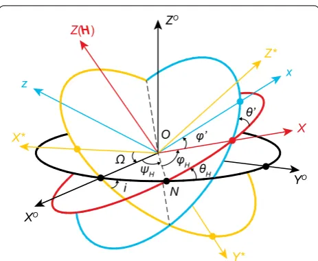
On the basis of the rotational motion model with 6 main parameters H, ψH , θH , ϕH , θ′ , and ϕ′ (Lin et al. 2016;
Crenshaw and Fitzpatrick 1968) shown in Fig. 4, we can establish the transformation between the body-fixed coordinate system and the orbital plane coordinate sys-tem. Define Rξ(η) as a rotation matrix around axis ξ with
angle η . Then, the transformation matrix from the orbital
plane coordinate system to the body-fixed system can be written as
The numerical test shows that this set of parameters is less sensitive to initial values than other parameter sets (such as the set with the traditional Euler angles and angular velocity vectors), which is beneficial for the cal-culation. Then, the unit vector to the observation station in the body-fixed system can be expressed as
(1) Tob=ROz(ϕ′)ROX(θ′)ROZ(ϕH)RON(θH)ROZO(ψH).
(2)
S=S(SJ2000,σ,H,ψH,θH,ϕH,θ′,ϕ′),
where SJ2000 is the unit vector from Tiangong-1 to the observation station in the J2000.0 coordinate system and
σ are the orbital elements. These values are known
varia-bles. Then, the relative distance of the two CCRs in Fig. 2 is written as
(3)
�P= −S·(P0+δP),
x y
z
y
x
H ω L=Iy / Iz
8° 6° 4°
2° 10°
O
Fig. 3 Trajectories of the estimated angular momentum and angular velocity of Tiangong‑1 in the inertia ellipsoid. The right panel shows the inertia ellipsoid of Tiangong‑1. According to Euler’s kinematics equation, the angular momentum H (blue) and the angular velocity ω (red) precess around one of the principal axes in the body‑fixed system without external torque. The left panel presents the projections of the trajectories in the xy plane. The rings label the angles of deviation from the z‑axis. Define L=H2/2EIz , where E is the self‑spin kinetic energy. Then, the trajectories correspond to L=0.9983 . The brown line in the right panel is the polhode (the trajectory of the angular velocity) at L=Iy/Iz
XO
Y* X*
YO
z x
X O
Z(H) ZO
Z*
Ω
i
ψH θH
φH
θ’ φ’
N
Fig. 4 Coordinate systems and 6 main parameters (Lin et al. 2016). The orientation of the OX∗Y∗Z∗ system is fixed in the space. The
OX0Y0Z0 system is the orbital coordinate system. The Oxyz system is the body‑fixed system shown in Fig. 1. The Oxyz system is a system associated with the self‑spin angular momentum vector H . The Oxyz system can be obtained from the OX∗Y∗Z∗ system by successive rotations through angles �,i,ψH,θH,ϕH,θ′ and ϕ′ , where is the
undetermined distance factor to correct the deviation from the centers of the CCRs, as mentioned above. A rotational motion mode can then be obtained using a genetic algorithm that satisfies the changes in P in the
observation data.
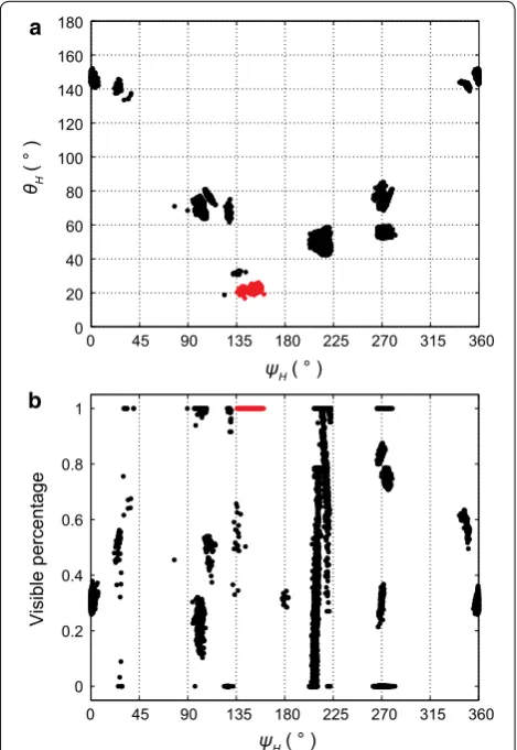
Usually, multiple possible solutions are obtained for the data from a single pass. Figure 5a shows the solutions for two main parameters, ψH and θH , which are the spherical
coordinates of the self-spin angular momentum H in the orbital plane system. Hence, we need to screen all solu-tions to eliminate false ones, including inspecting the vis-ibility of the CCRs in the observation geometry (Fig. 5b) and comparing the results from other adjacent passes, i.e., choosing similar values of θH and L and
conform-ing the change in ψH to the law. This process eventually
Solutions of angular momentum magnitude
Determining the exact angular momentum magnitude H
is another challenge. Directly solving the rotational speed is extremely difficult because the valid observation dura-tion in a single pass is much smaller than the rotadura-tion period of Tiangong-1, the time interval between adjacent passes is much larger than this rotation period, and the large dimension of the algorithm makes P not sensitive
to the changes in H.
However, the direction of the angular momentum ( ψH , θH ) can be accurately determined in a single pass,
and the solution in each pass is a mutually independent process (Fig. 6). Due to the influence of the gravity gra-dient torque, the angular momentum precesses around the normal of the orbital plane. Variations in ψH can be reduced to a first-order secular linear change and a sec-ond-order periodic change (Lin et al. 2016). For a triax-ial ellipsoid model, the linear change rate of ψH can be approximated as
where i is the orbit inclination, ˙ is the orbital precession
caused by the oblateness of the Earth, G is the gravita-tional constant, M is the mass of the Earth, R is the geo-centric radius, and θ¯H , θ¯′ , and ϕ¯′ are the mean values of θH , θ′ , and ϕ′ , respectively (Lin et al. 2016). The
first-order linear change rate of ψH is approximately linear
with 1/H. This correspondence is easy to understand because the gravity gradient torque is independent of the angular momentum, and under the same gravity gradient torque effects, the smaller the magnitude of the angular momentum is, the more easily the direction is changed, which results in a faster change rate.
Therefore, the magnitude of the current angular momentum H can be obtained from the change in ψH
from two passes based on the relationship between H and the precession rate of the angular momentum. In actual operation, the resulting error will be excessive if the two passes are too close, and if their time interval is too long, the large difference in orbital altitudes will affect the ψH
–H relationship. Therefore, we select the interval from the observations to be more than half a day and less than 10 days to calculate the change in ψH . After
momentum can be obtained by numerically calculating the ψH–H relationship (Fig. 7).
Results and discussion Tiangong‑1’s rotational state
The evolution of the rotational state of Tiangong-1 can be expressed by the variation of its self-spin angular momentum because the angular momentum is the con-served quantity in the rotational motion of a rigid body
without external torque. Derived from the estimation results, the angular momentum H of Tiangong-1 devi-ates from its z-axis (i.e., the maximum principal axis of inertia) with maximum angles of approximately 1◦ and 8.5◦ in the x and y directions, respectively (Fig. 3), while in the inertial space, the angular momentum H precesses around the normal direction N of the orbital plane due
to gravity gradient torque (Lin et al. 2016) at an angle
θH =23.1◦± 2.5◦ (Fig. 8). During the 5-month
obser-vation period, the rotation mode of Tiangong-1 was relatively stable, indicating that the satellite was not sub-jected to a strong sudden effect (such as a collision). Any dissipating effect in space will cause the angular momen-tum to migrate to the axis of maximum inertia (the rota-tion with the lowest energy), but Tiangong-1’s angular momentum remained at a certain angle to the z-axis for a long duration. A numerical test showed that gravity gra-dient torque produces only periodic deviations of up to 0.01◦ (along the x-axis) and 0.1◦ (along the y-axis).
There-fore, we speculate that Tiangong-1 was also subject to other effects, which may be additional stable driving tor-ques. Combined with the attitude of Tiangong-1 before losing attitude control (Fig. 8), these effects may have caused the Oz-axis to be deflected by approximately 90◦
in the normal direction of the orbit plane, finally reaching a balanced state.
An accurate magnitude of the angular momen-tum H can be derived through the relationship of H
with the precession rate of the angular momentum due to the gravity gradient torque, thus enabling the 0
0.1 0.2
0 0.1 0.2 0.3
Probability densit
y
100 110 120 130 140 150 160 170 180
0 0.02 0.04
ψH( ° ) UTC 11.1 h
UTC 9.5 h
UTC 12.6 h
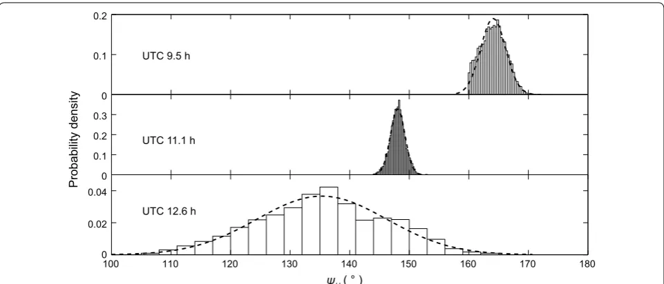
Fig. 6 Probability distributions of the estimated ψH . The three sets of data are estimated from three consecutive passes on January 18, 2018, at UTC 9.5 h, 11.1 h, and 12.6 h. Due to the influence of the gravity gradient torque, ψH will increase or decrease at a certain rate, which can be used to find the correct solution in Fig. 5 and calculate the magnitude of the angular momentum in Fig. 7
0.8 0.9 1 1.1 1.2 −280
−260 −240 −220 −200 −180 −160
H / Iz (°/s) ωψH
( ° / Day
)
Fig. 7 Relation between the change rate of ψH and the equivalent rotation speed H/Iz . The relation example is estimated from Fig. 2 where the orbit altitude is approximately 280 km. A series of parameter sets of rotational motion, which are not sensitive to H, are obtained using Eq. (3). We use each set of parameters as initial values to extrapolate the rotation and extract the change rate of ψH . Then, we can establish a mapping from H/Iz to ωψH . Once the change in ψH
variation in rotational speed with time to be obtained (Fig. 9). The rotational speed of Tiangong-1 increased in the 5 months before reentry. This acceleration phe-nomenon has been verified by a very small amount of imaging and radar data. Although a complete period evolution cannot be obtained from these additional data, the detected rotational speed in early 2018 is clearly faster than that at the end of 2017. As men-tioned in Introduction, this difference is an unexpected phenomenon. Within the known major external tor-ques in space, the gravity gradient torque generally acts as a conservative torque and does not have a secular effect on the angular momentum (Lin et al. 2016; Cren-shaw and Fitzpatrick 1968; Holland and Sperling 1969; Hitzl and Breakwell 1971). The eddy current torque and magnetic torque are dissipative torques that decrease the rotational speed (Smith 1962; Williams and Mead-ows 1978; Praly et al. 2012; Lin and Zhao 2015). Light pressure torque may theoretically have a slight accel-eration effect under specific orbit and attitude config-urations (Kucharski et al. 2016), but no secular effect was found in our numerical test on Tiangong-1. Classic aerodynamic torque, which affects objects only at very low orbital altitudes (Williams and Meadows 1978; Lyle and Stabekis 1971; Hart et al. 2014), will also decrease rotational speed (blue line in Fig. 9).
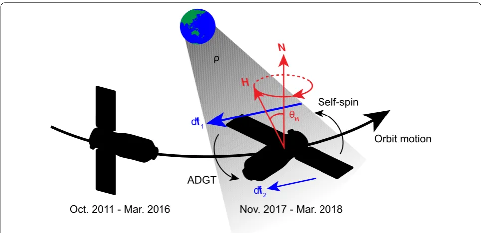
Atmospheric density gradient torque
However, we conjecture that the upper atmosphere is the factor causing the increase in the rotational speed because the acceleration of the spin increases significantly with decreasing orbital altitude, which is consistent with the increase in atmospheric density with decreasing orbital altitude. In this regard, we propose an atmospheric den-sity gradient torque (ADGT) model (Fig. 8), which takes into account the torque generated by the change in atmos-pheric density with orbital altitude at the satellite scale. For the rotational state of Tiangong-1, the ADGT is nearly in the same direction as the angular momentum, resulting in an acceleration effect. The atmospheric density gradient at Tiangong-1’s position after February 2018 also increases faster (upper panel of Fig. 9), which is consistent with the increasing accelerated rate of the rotational speed.
We can estimate the order of magnitude of this new torque. As shown in Fig. 9, the rotational speed increased by approximately 0.2◦s−1 from Decem-ber 1, 2017, to February 1, 2018. Then, the change rate of the angular momentum can be estimated as �H/�t∼5×10−6kg m−2s−2 . Considering the classic
atmospheric force formula, the difference in the forces acting at a distance L∼5 m is
(5) �F= −1
2CdAv 2Ldρ N
H
θH
df1
df2
ADGT
Self-spin
Orbit motion
ρ
Nov. 2017 - Mar. 2018 Oct. 2011 - Mar. 2016
Fig. 8 Rotational state of Tiangong‑1 and atmospheric density gradient torque. The left model presents the normal attitude of Tiangong‑1 during its active operational life. The Ox‑axis of the body‑fixed system points in the forward direction, and the Oz‑axis points to the zenith. The right model presents the rotational state of Tiangong‑1 during the joint observation. The angular momentum H precesses in space around the normal of the orbital plane N with the angle θH=23.1◦±2.5◦ . The precession speed ranges from approximately −280◦day−1 (November 2017) to −160◦day−1 (March 2018). The shadow shows that the atmospheric density ρ decreases with increasing orbital altitude. Therefore, the atmospheric force df1 at
where the drag coefficient Cd∼2 , the projected area of satellite normal to the incident flow A∼10 m2 , the velocity of the satellite v∼8×10³m s−1 , and the
gradi-ent of the density in the direction of the orbital altitude
dρ∼3×10⁻¹⁶kg m−4 (taking the value on January
1, 2018 in the upper panel of Fig. 9). Then, the ADGT can be estimated as T ∼LF ∼5×10⁻⁶kg m−2s−2 , which is in line with the increasing rate of the angular momentum.
To verify our ADGT model, we performed a numeri-cal simulation using actual orbital and space environment parameters with aerodynamic torque based on the molecu-lar–surface interaction model (Lyle and Stabekis 1971; Hart et al. 2014) and taking gravity gradient torque into account. The aerodynamic force acting on a unit surface element is
where nˆ is the normal of the surface, τˆ is the tangential
vector, θi is the incident angle, dA is the area of the unit surface element, and σN and σT are the normal and
tan-gential momentum exchange coefficients, which both take an empirical value of 0.8 (Lyle and Stabekis 1971). The atmospheric density
(6) df = −ρv2cosθi(2−σN)cosθinˆ−σTsinθiτˆdA,
(7)
ρ=ρ0+�h·dρ,
where ρ0 is the atmospheric density at the center of mass
and h is the altitude difference from the center of mass.
The aerodynamic torque is
where r is the body-fixed coordinate vector of the unit
surface element and δ is the correction coefficient of the
force that we add to account for unknown effects.
Normally, δ is set to 1. The acceleration effect of the
ADGT, which is independent of rotational speed, over-comes the deceleration effect of classic aerodynamic torque (the brown and cyan lines in Fig. 9). However, a gap exists between the simulation results and the meas-ured data. If we multiply the force from the molecule– surface interaction model by a coefficient δ=3 in the numerical simulation, we can obtain a result that is simi-lar to the measured data (red line in Fig. 9). Hence, the acceleration effect may have a strong correlation with the atmospheric density gradient, and the ADGT model can be inferred to qualitatively conform to the actual situa-tion. The atmospheric density model used in Fig. 9 is MSIS 90. We have also compared other models such as Ciral1972, DTM1994, and JB2008, and their results are not significantly different.
If we assume that the ADGT model is valid, the atmos-pheric force acting on Tiangong-1 is larger than that in the molecule–surface interaction model, which indicates
(8) dT=r×(δ·df),
10−16 10−15
2017.12.1 2018.1.1 2018.2.1 2018.3.1
0.7 0.8 0.9 1.0 1.1 1.2 1.3 1.4 1.5
Equivalent rotation
speed (°/s
)
Atmospheric densit
y
gradient (kg/m
4)
3df with θp = 90° θp = 90° θp = 0°
dρ= 0
Fig. 9 Variation in equivalent rotational speed (lower panel) and the corresponding atmospheric density gradient (upper panel). The abscissa is the date, and the ordinate is given in logarithmic coordinates. In the upper panel, the atmospheric density gradient (unit: kg m−4 ) is the gradient of the atmospheric density at the altitude of Tiangong‑1’s position. The atmospheric density model is MSIS 90, and the orbital and space environment parameters are all actual values. In the lower panel, the black point is the equivalent rotation speed H/Iz (unit: ◦s−1 ), which is estimated from the observational data. The error bar marks the range of one standard error. The four curves present the numerically calculated evolutions of the equivalent rotational speed. Each curve has a short‑term oscillation with an amplitude of no more than 0.01◦/s . The blue represents the result
being under free molecular flow (Hart et al. 2014), and the density has been regarded as constant at the satel-lite scale. Here, the density gradient is taken into con-sideration; thus, the accuracy of the molecular–surface interaction model may not match the accuracy required for modeling weak aerodynamic torques. Further refine-ments are needed to establish an in-depth atmosphere– surface interaction model. Other minor effects, such as multiple reflection or hydrodynamic effects, that were omitted in classic models should be considered in further research.
Conclusions
By processing Tiangong-1’s laser ranging data, we obtained the rotational state in the 5 months before reen-try and detected an unexpected increase in rotational speed. Then, we proposed a new torque model ADGT to explain this spin acceleration. Because we are unable to determine the status of solar panels, we performed our simulations for two extreme cases, i.e., the pan-els are parallel ( θp=0◦ ) and perpendicular ( θp=90◦ )
to the xy plane, respectively. Although several times weaker than the measured data, the acceleration effect due to the ADGT model is still a non-negligible fac-tor in the increasing angular velocity of Tiangong-1. This effect provides a new explanation for the mecha-nism of the observed rotation acceleration of extremely low-orbit objects. The data on the rotational evolution of Tiangong-1 obtained during the 5-month-long joint observations will help to improve the relevant mod-els and to promote research on the rotational evolution of extremely low-orbit objects, which has an important impact on the prediction of reentry, satellite attitude con-trol, and the overall active debris removal strategy. More observations of extremely low-altitude debris objects are needed to better understand the cause of the rotational acceleration of Tiangong-1 prior to reentry.
Authors’ contributions
HYL and CYZ conceived and designed the study. TLZ and ZPL performed the processing of raw data. DW, WZ, JNX, and JWZ performed orbit determination and scheduled the observation plans. XWH, HFZ, ZBW, YQL, QLS, HTZ, and HRD performed satellite laser ranging and contributed data. CZ and YDP pro‑ cessed the photometry and imaging data for verification. HYL and TLZ wrote the manuscript. All authors read and approved the final manuscript.
Author details
1 Purple Mountain Observatory, Chinese Academy of Sciences, Nan‑ jing 210034, China. 2 Changchun Observatory, National Astronomical Obser‑ vatories, Chinese Academy of Sciences, Changchun 130117, China. 3 Shanghai Astronomical Observatory, Chinese Academy of Sciences, Shanghai 200030, China. 4 Chinese Academy of Surveying and Mapping, Beijing 100830, China. 5 Yunnan Observatories, Chinese Academy of Sciences, Kunming 650216, China. 6 Key Laboratory of Space Object and Debris Observation, Chinese Academy of Sciences, Nanjing 210034, China.
Competing interests
The authors declare that they have no competing interests.
Availability of data and materials
The dataset supporting the conclusions of this article is available in the Zenodo repository, https ://doi.org/10.5281/zenod o.14522 98.
Funding
This research was supported by the National Natural Science Foundation of China (Grant Nos. 11533010 and 11703095), the Youth Innovation Promotion Association, CAS (Grant No. 2018353), and the Chinese Academy of Sciences Foundation (Grant No. KGFZD‑135‑16‑012).
Publisher’s Note
Springer Nature remains neutral with regard to jurisdictional claims in pub‑ lished maps and institutional affiliations.
Received: 24 October 2018 Accepted: 31 January 2019
References
Boehnhardt H, Koehnhke H, Seidel A (1989) The acceleration and the decelera‑ tion of the tumbling period of Rocket Intercosmos 11 during the first two years after launch. Astrophys Space Sci 11:297–313
Bonnal C, Ruault JM, Desjean MC (2013) Active debris removal: recent progress and current trends. Acta Astronaut 85:51–60. https ://doi.org/10.1016/j. actaa stro.2012.11.009
Crenshaw JW, Fitzpatrick PM (1968) Gravity effects on the rotational motion of a uniaxial artificial satellite. AIAA J 6(11):2140–2145. https ://doi. org/10.2514/3.4946
Deluca LT, Bernelli F, Maggi F, Tadini P, Pardini C, Anselmo L, Grassi M, Pavarin D, Francesconi A, Branz F, Chiesa S, Viola N, Bonnal C, Trushlyakov V, Belokonov I (2013) Active space debris removal by a hybrid propul‑ sion module. Acta Astronaut 91:20–33. https ://doi.org/10.1016/j.actaa stro.2013.04.025
Hart KA, Dutta S, Simonis KR, Steinfeldt BA, Braun RD (2014) Analytically‑ derived aerodynamic force and moment coefficients of resident space objects in free‑molecular flow. In: AIAA SciTech, AIAA atmospheric flight mechanics conference, National Harbor, MD
Hitzl D, Breakwell J (1971) Resonant and non‑resonant gravity‑gradient pertur‑ bations of a tumbling tri‑axial satellite. Celest Mech 3(3):346–383 Holland RL, Sperling HJ (1969) A first‑order theory for the rotational motion of
a triaxial rigid body orbiting an oblate primary. Astron J 74:490–496. https ://doi.org/10.1086/11082 6
Koshkin N, Korobeynikova E, Shakun L, Strakhova S, Tang ZH (2016) Remote sensing of the EnviSat and Cbers‑2B satellites rotation around the centre of mass by photometry. Adv Space Res 58(3):358–371. https ://doi. org/10.1016/j.asr.2016.04.024
Kucharski D, Kirchner G, Lim HC, Koidl F (2013) New results on spin determina‑ tion of nanosatellite BLITS from high repetition rate SLR data. Adv Space Res 51(5):912–916. https ://doi.org/10.1016/j.asr.2012.10.008
Kucharski D, Bennett JC, Kirchner G (2016) Laser de‑spin maneuver for an active debris removal mission—a realistic scenario for Envisat. In: Pro‑ ceedings of the advanced maui optical and space surveillance technolo‑ gies conference, Held in Wailea, Maui, Hawaii, 20–23 Sept 2016 LaPaz L, Wilson RH (1960) Magnetic damping of rotation of the Vanguard I
satellite. Science 131:355–357
Lin H‑Y, Zhao C‑Y (2015) Evolution of the rotational motion of space debris acted upon by eddy current torque. Astrophys Space Sci 357(2):167. https ://doi.org/10.1007/s1050 9‑015‑2396‑2
Lin H‑Y, Zhao C‑Y, Zhang M‑J (2016) Frequency analysis of the non‑principal‑ axis rotation of uniaxial space debris in circular orbit subjected to gravity‑gradient torque. Adv Space Res 57(5):1189–1196. https ://doi. org/10.1016/j.asr.2015.12.036
Liou J‑C (2011) An active debris removal parametric study for LEO envi‑ ronment remediation. Adv Space Res 47(11):1865–1876. https ://doi. org/10.1016/j.asr.2011.02.003
Liou J‑C, Johnson NL (2009) A sensitivity study of the effectiveness of active debris removal in LEO. Acta Astronaut 64(2–3):236–243. https ://doi. org/10.1016/j.actaa stro.2008.07.009
Lyle R, Stabekis P (1971) Spacecraft aerodynamic torques. In: NASA SP‑8058 Markeyev AP (2006) Theoretical mechanics. Higher Education Press, Beijing Meeus J (1971) Satellites artificiels—Observations de périodes photométr‑
iques 1968–1971. Ciel et Terre 87:606
Pearlman MR, Degnan JJ, Bosworth JM (2002) The international laser ranging service. Adv Space Res 30(2):135–143. https ://doi.org/10.1016/S0273 ‑1177(02)00277 ‑6. arXiv :1011.1669v 3
Pittet JN, Šilha J, Schildknecht T (2018) Spin motion determination of the Envisat satellite through laser ranging measurements from a single pass
measured by a single station. Adv Space Res 61:1121–1131. https ://doi. org/10.1016/j.asr.2017.11.035
Praly N, Hillion M, Bonnal C, Laurent‑Varin J, Petit N (2012) Study on the eddy current damping of the spin dynamics of space debris from the Ariane launcher upper stages. Acta Astronaut 76:145–153. https ://doi. org/10.1016/j.actaa stro.2012.03.004
Shan M, Guo J, Gill E (2016) Review and comparison of active space debris capturing and removal methods. Prog Aerosp Sci 80:18–32. https ://doi. org/10.1016/j.paero sci.2015.11.001
Smith G (1962) A theoretical study of the torques induced by a magnetic field on rotating cylinders and spinning thin‑wall cones, cone frustums, and general body of revolution. In: NASA eTR R‑129
Tapley BD, Bettadpur S, Watkins M, Reigber C (2004) The gravity recovery and climate experiment: mission overview and early results. Geophys Res Lett. https ://doi.org/10.1029/2004G L0199 20
Williams V, Meadows AJ (1978) Eddy current torques, air torques, and the spin decay of cylindrical rocket bodies in orbit. Planet Space Sci 26:721–726 Wilson RH (1959) Magnetic damping of rotation of satellite 1958β2. Science