Design and Development of a Slender Dual-Structure Continuum Robot
for In-situ Aeroengine Repair
Mingfeng Wang
1, David Palmer
1, Xin Dong
1∗, David Alatorre
1, Dragos Axinte
1, Andy Norton
2Abstract— In-situ aeroengine maintenance works (e.g. inspec-tion, repair) are highly beneficial as it can significantly reduce currently accepted maintenance cycle which is extensive and costly due to the need to remove engines from the wing of an aircraft. However, feeding in/out via inspection ports and performing a multi-axis movement of an end-effector in a very constrained environment such as aeroengine combustion chamber is a fairly challenging task. This paper presents the design and development of a highly slender (i.e., low diameter-to-length ratio) dual-structure continuum robot with 16 degrees of freedom (DoFs) to provide the feeding motion needed to navigate into confined environments and then perform a required configuration shape for further repair operation. This continuum robot is a compact system and presents a set of innovative mechatronic solutions such as: (i) two-stage tendon-driven structure with bevelled disk design to perform required configuration shape and to provide selective stiffness for the ability of taking high payloads; (ii) various compliant joints to enable different flexibility requirement in each stage; (iii) three commanding cables for each 2-DoF section to minimise the number of actuators with a precise actuation. To be able to achieve the desired configuration shape, a kinematic model has been established and the configuration-cable kinematics has been implemented. Finally, the continuum robot has been built and tested for performing the predefined configuration shape.
I. INTRODUCTION
In-situ aeroengine repair can significantly reduce currently accepted maintenance cycle which is extensive and costly due to the need to remove engines from the wing of an aircraft to fully strip and overhaul. Over the past decade, robots have been integrated into many service operations around the world and have enabled or improved many new in-situ aeroengine repair technologies [1]. Currently, most employed devices are either rigid-segmented boreblending tools [2] with one DoF or flexible ones with two DoFs to perform bending movement in two directions [3]. However, the current designs of these devices are unable to cover a wide range of maintenance works as the limited DoFs and articulated lengths (10-30 mm), which prevent them to reach intervention places far away from the accessing ports.
Continuum robots, as a subset of hyper-redundant manip-ulators [4] which utilize compliant joints in series to create a highly flexible and compliant arm capable of intricate and
*Research supported by the Aerospace Technology Institute (UK) and Rolls-Royce Plc (Corresponding author: Xin Dong)
1Mingfeng Wang, David Palmer, Xin Dong, David Alatorre, Dragos
Axinte are with the Rolls-Royce UTC in Manufacturing and On-Wing Technology, University of Nottingham, Nottingham, NG8 1BB, UK
{Mingfeng.Wang, David.Palmer, David.Alatorre,
Xin.Dong, Dragos.Axinte}@nottingham.ac.uk
2Andy Norton is with Rolls-Royce plc, Derby, DE24 8BJ, UK
complex motions, have the potential to further advance the benefits of in-situ aeroengine repair and make new proce-dures possible. Typically the continuum robots are either used for grasping [5] or inspecting and performing actions in restrictive environments [6]. This paper focuses on the latter. Generally robots of this nature are designed to be all-round performers, with every joint having the same reach and constraints. The reasoning behind this is to make the systems suitable for most scenarios not a singular case, which is true of [7] [8], and therefore separate themselves from purpose-built mechanisms. There are some scenarios where this broad approach is not suitable, one such case is a torus shaped envi-ronment with confined entrances (e.g., aeroengine combustor chamber). In this situation, significantly different from the current designs of medical continuum robots (5-12 mm in diameter but only 10-30 mm articulated lengths), the robot has to come with a slender design (i.e., low diameter-to-length ratio) and perform a singular tight bend and then continuous shallow curve.
To address these needs and challenges, this paper reports on a design and development of a slender (diameter-to-length ratio < 0.02) dual-structure continuum robot that provides adequate number of DoFs (16) and high length (715 mm), which makes it able to feeding in/out of the constrained environments via confined inspection ports and then to perform a required (C-c) configuration shape for further repair operation purpose. In II, the mechanical design of the continuum robot is presented in terms of the technical requirements, conceptual design and corresponding main specifications. Then, a kinematic model is established based on a piecewise constant-curvature theory and corresponding configuration-cable kinematics is implemented in III. Finally, IV deals with the experimental setup for validating test of the built prototype and the characterization of the performance of the built continuum robot.
II. MECHANICALDESIGN
The technical requirements, conceptual design and cor-responding main specifications of a slender dual-structure continuum robot are presented in this section, respectively. The continuum robot consists of two stages: body section and tip section, in which two different types of bevelled disks and backbones are adopted, respectively.
A. Technical Requirements
the limitations for the proposed slender continuum robot are specified as follows:
• Limited inspection ports - the potentially useful
borescope ports are limited in the combustor due to ancillary equipment attached to the engine casing;
• Minimum overall length sufficient to ensure all of
the aeroengine combustor can be covered via limited inspection ports;
• Maximum diameter to allow access from all of the
selected inspection ports of the aeroengine combustor;
• Maximum section length and minimum section bend
angle to traverse inside of the combustor by following the constant-curvature middle line of the combustor; • Minimum internal diameter appropriate to allow enough
space in the central for accessing inspection and repair tools;
• Minimum payload of 0.25 kg at the tip to ensure
appropriate end-effectors (e.g., inspection and repair tools) can be adopted.
B. Conceptual Design
To perform the requested in-situ repair tasks for specific aeroengines, a conceptual design of the slender dual-structure continuum robot is proposed, as shown in Fig 1.
To satisfy two main purposes (i.e., feeding in/out and repair) and reduce the complexity, a two-stage tendon-driven structure is adopted in the proposed conceptual design (see Fig 1(a)). In these two stages, the first stage, i.e., body, con-sists of ten 1-DoF sections and is able to feeding in/out with full coverage of entire aeroengine combustor via inspection ports, whilst the second stage, i.e., tip, consists of three 2-DoF sections and is capable of performing 6-2-DoF movements for feeding in/out and repair, thus, the entire continuum robot has 16 DoFs allocated to 13 sections.
Combustion chamber
C-shape
c-shape
3
Motors
(b) An aero-engine combustor
(c) Accessing in/out stratagy
(1) (2)
(3) (4)
(5) (6)
Tip Body
(a) Dual-structure design
Fig. 1. A graphic representation of the conceptual design of the proposed dual-structure slender continuum robot: (a) a dual-structure design; (b)an aeroengine combustor; (c) a accessing in/out strategy.
A section-by-section strategy (see Fig. 1(c)) is used for feeding in/out the combustor since the section cannot start the bending movement before fully accessing into the combustor (the robot will collide with the edge of the panels) and correspondingly a C-c configuration shape of the continuum robot will be generated inside the combustor (see Fig. 1(b)) for further repair operations.
To achieve high payload capability at the tip and com-pensate the self-weight, a tendon-based and extrinsically actuated approach is applied in the continuum robot, where a pair of cables and a group of three cables are allocated in each body section and tip section, respectively. Furthermore, to prevent the backlash and slack, all cables are fully actuated which means 29 cable/motors (Maxon spindle drive: GP-32-S-363904) in total are applied.
C. Mechanical Specification
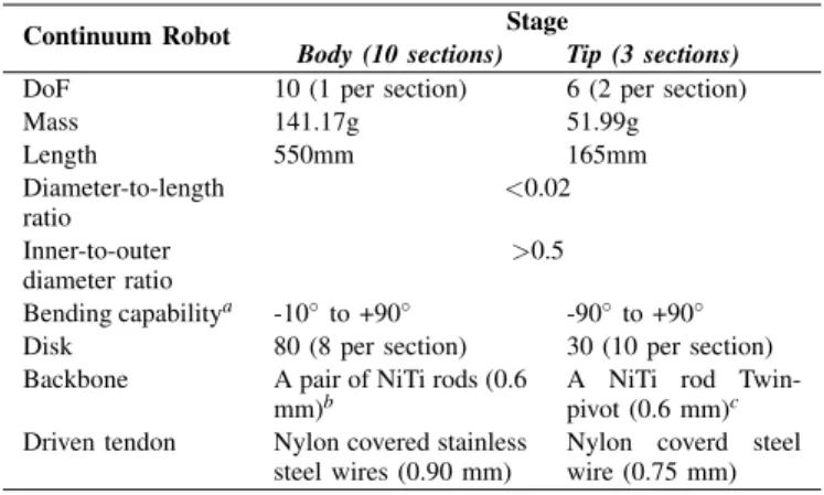
The main specifications of mechanical design of the pro-posed dual-structure slender continuum robot are shown in 2 and listed in Table I.
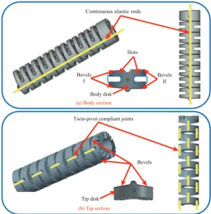
A bevelled disk design with specific slopes is applied in the proposed continuum robot. In each disk of the body sections (see Fig. 2(a)), there are two bevels with the identical slope on one side and the slopes are different on two sides to perform a C-c bending shape, which is determined by the factors of the interval distance and the constant-curvature middle line of the combustor chamber. In each disk of the tip sections (see Fig. 2(b)), the slopes of four bevels on both sides are the same while two bevels on one side alternate at 90◦relative to the other side.
To achieve the light weight and enable the mechanical ca-pabilities, the disks in the continuum robot are designed and manufactured by the titanium alloy because of its physical and mechanical properties such as light weigh, high tensile
(b) Tip section Twin-pivot compliant joints
Tip disk
Bevels (a) Body section
Continuous elastic rods
Bevels I
Bevels II Slots
Body disk
TABLE I
MAIN SPECIFICATION OF THE CONTINUUM ROBOT
Continuum Robot Stage
Body (10 sections) Tip (3 sections) DoF 10 (1 per section) 6 (2 per section)
Mass 141.17g 51.99g
Length 550mm 165mm
Diameter-to-length ratio
<0.02
Inner-to-outer diameter ratio
>0.5
Bending capabilitya -10◦to +90◦ -90◦ to +90◦ Disk 80 (8 per section) 30 (10 per section) Backbone A pair of NiTi rods (0.6
mm)b
A NiTi rod Twin-pivot (0.6 mm)c Driven tendon Nylon covered stainless
steel wires (0.90 mm)
Nylon coverd steel wire (0.75 mm)
a. Bending capability in each section; b. A pair of NiTi rods run through all body sections; c. A NiTi rod twin-pivot is allocated between two disks (i.e.,one segment).
strength and toughness [9]. In each disk of body sections, two optimised slots have been placed to reduce the self-weight by almost 28% (see Fig. 2(a)).
In the body sections, a pair of continuous elastic rods (NiTi rods) is applied to enable the physical capabilities which motivate the continuum robot to adapt the backbone shape to conform the robot to the constant-curvature middle line of the combustor chamber (C-c shaped planar deformation). However, in the tip sections, to ensure the high flexibility and enhance torsional stability relative to the axis of the structure, a twin-pivot compliant joints (short NiTi rods) (alternating at 90◦to account for 2 DoFs in each section) structure [10] is adopted (see Fig. 2(b)).
III. KINEMATICSANALYSIS
In this section, a piecewise constant-curvature theory based kinematic model is derived to form the basis for mechanical design, actuation specification and controller development.
A. Kinematic Model
The proposed continuum robot is divided into two stages (i.e., body and tip), as shown in Fig. 1, where the first stage (sections 1 to 10) can be modelled as a planar continuum manipulator and the second stage (sections 11 to 13) can be a spatial continuum manipulator. A tip-following algorithm based initial navigation strategy [11] is applied to generate the path for the entire robot and it allows the user to feed in the tip through a restrictive environment with the body following the tip’s path. As aforementioned, in this case, only the tip sections are used for performing repair tasks whilst the body sections are formed with C-c shape, which means the continuum robot is in an optimal position for operation with sections 1-10 fixed.
Based on piecewise constant-curvature theory, the con-tinuum robot kinematics are generally decomposed into two submappings [12]. One is between joint or actuator space (e.g., length of cable, deformation of push rods/tubes, pressure of tube, etc.) and configuration space (i.e., arc
X
Y Z(Zbi)
O X1
Y1 Z1
O1 X11
O2 Z2
Y2
X2 Xi
Yi Zi
Oi O11 Y11 Z11 Z14 Y14
X14 O14
Xbi Xi+1
Yi+1 Zi+1
Oi+1
Yi Zi
Oi Yi+1 Zi+1 Oi+1
Z13 Y13
O13 X13
(c) 2-DoF segment
(b) 1-DoF segment
Z”’ Z” Y”’ Y”
Y’
X’ X” X”’ Z’
Cable 1
Cable 2 Cable 3
Twin-pivot Joint 1
Twin - pivot Joint 2
’
”
2 φi1
φi1 ∙sin
(a) one body disk
∙sin φi1
φi2 /2
/2
3
Fig. 3. Schematic for a kinematic model of the continuum robot: (a) top view of one disk (b) a single segment of the 1-DoF structure with continuous backbones in body sections; (c) a single segment of the 2-DoF structure with twin-pivot compliant joints in tip sections.
parameters in terms of the curvatureκ , the rotational angle φ and the arc length `), while the other is between this configuration space and task space (i.e., position and pose of the end-effector). Furthermore, the former is a robot-specific mapping which means the kinematics varies with different actuation approaches (e.g., tendon-driven, flexible push rods/tubes, pneumatic tubes, etc.), while the latter is a robot-independent mapping which is general and applies to each independent actuated section.
To implement the kinematic analysis, the coordinate frames in terms of world frame, base disk frame {Oi}(i= 1, ...,13), end-effector (end disk of 13th section) frame {O14}, and bending frames {Bi} are established (see Fig. 3 and Table II). Since tendon-driven is chosen as the actuation approach (i.e., the backbone arc is shaped by driving cables), the actuator space variables (i.e., the cable lengths) in ith section can be written in the forms of Li = [li1,li2,li3]T,
whereli3 equals to zero in sections 1-10 since only a pair
of cables is utilized. The general kinematic representation of configuration space (arc parameters q = [κ,φ, `]T) is illustrated referring to world frame {O} in Fig. 2, and the arc geometry relationships can be presented as
θ=κ·`
r=1/κ (1)
whereθ is the bending angle and r is the bending radius. Specifically, the +Zi−axes are considered to be always tangent to the constant-curvature curve and positive curvature (κ>0) produces bending towards the+Xbi−axes. Further-more, the task space (i.e., the position and orientation of the end-effector) is represented by the position of the last disk centre O14= [x14,y14,z14]T and the rotation matrix of the
frame{O14}:0R14∈ℜ3×3.
B. Configuration-Cable Kinematics
continuum robot. In this subsection, our scope is focused on the configuration-cable kinematics which provides the required input data for the experimental test of feed in/out with C-c shaped configuration in IV.
Once the aforementioned kinematic model is established, the purpose of configuration-cable kinematic analysis is to solve the mathematics to describe the lengths of cablesL=
[L1,· · ·,L13]T relative to the given bending arc configuration
in each section qi = [κi,φi, `i]T. Note that the cables are allocated to different holes in each disk with different pitch circle diameters (PCDs: Dr1 and Dr2) and phase angles ϕi= [ϕi1,ϕi2,ϕi3]T (see Fig. 3(a)), the projection of each
cable hole’s PCD on bending plane can be expressed as
Dr1·sinϕi j
,when i=1, ...,10
Dr2·sinϕi j
,when i=11,12,13
(2)
Furthermore, as each section includes identical segments and two different section structures are applied in body and tip respectively, the configuration-cable kinematics can be expressed by analysing two single segments in which one is from the body (Fig. 3(b)) and the other is from tip (Fig. 3(c)).
In Fig. 3(b), a single segment, which includes two adjacent disks and a continuous compliant joint, represents a basic 1-DoF structure inith section (body). Noting that the through-disk cable lengths are constant, the contribution of arc parameters to the entire cable length only relates to the sum of changes of gap cable length ∆Li. According to the geometry relationships, the change of gap cable length can be expressed as (see Appendix for detail derivation)
∆li1=
2·|Dr1·sinϕi1|·
h
sin(θs1−∆2θi)−sin(θs1)
i
cosθs1
∆li2=
2·|Dr1·sinϕi2|·
h
sin(θs2+∆2θi)−sin(θs2)
i
cosθs2
(3)
where θs1 and θs2 are the slope angles of two planes,
re-spectively and the∆θiis the segment bending angle with the bending angleθiwhich can be obtained by (1). Furthermore, the total change in length of the cable in theithsection (body) can be obtained by taking into account the disk number in each body section,Nbody.
In Fig. 3(c), a single segment, which includes three ad-jacent disks and twin-pivot joints, represents a basic 2-DoF structure in the tip sections. A complete derivation of the
TABLE II
NOMENCLATURE
Symbol Description
{O}:O−XY Z World frame with origin,O, located at the
base
{Oi}:Oi−XiYiZi Base disk frame ofithsection(i=1, ...,13) with originOi at the centre
{Bi}:Obi−XbiYbiZbi Bending plane frame of ith section (i= 1, ...,13), where theithsection always bends in the ybizbi plane and the origin Obi is coincident withOi
{O14}:O14−x14y14z14 End disk frame of 13thsection with origin
O14at the centre
inverse kinematics of a twin-pivot compliant joints structure is given in [10]. However, due to four in two pairs of cables allocated to ordinary disks are used to shape the arc in [10] while a group of three cables through the bevelled disks are used in this case, the kinematics of the single segment needs to be discussed in detail. Referring to [10], the bending angles of twin-pivot joints 1 and 2 (i.e., ∆αi and ∆βi) in single segment can be expressed with respect to the bending and direction angles of the corresponding section as written by Eq. (18) in [10]. Based on the obtained angle values of ∆αi and ∆βi and similar geometry relationships in body segment, the change of cable lengths in gap 1 (with bending angle of∆αi) can be expressed as
∆l0i1=
2·|Dr2·sinϕi1|·
h
sin(θs3−∆2αi)−sin(θs3)
i
cosθs3
∆l0i2=
2·|Dr2·sinϕi2|·
h
sin(θs3−∆2αi)−sin(θs3)
i
cosθs3
∆l0i3=
2·|Dr2·sinϕi3|·
h
sin(θs3+∆2αi)−sin(θs3)
i
cosθs3
(4)
Similarly, the change of cable lengths in gap 2 (with bending angle of∆βi) can be written as
∆l00i1=
2·|Dr2·cosϕi1|·
h
sin(θs3−∆2βi)−sin(θs3)
i
cosθs3
∆l00i2=
2·|Dr2·cosϕi2|·
h
sin(θs3+∆2βi)−sin(θs3)
i
cosθs3
∆l00i3=
2·|Dr2·cosϕi3|·
h
sin(θs3+∆2βi)−sin(θs3)
i
cosθs3
(5)
Therefore, according to 4 and 5, the total change in length of the cable in theith section (tip) can be also obtained by taking into account the disk number in each tip section,Ntip.
IV. EXPERIMENTALVALIDATION
With the mechanical design and the key kinematic mod-elling commented, a prototype of the proposed continuum robot has been built as shown in Fig.4. The validation of the capabilities of this complex mechatronic system has been performed to check some key characteristics to the targeted demonstration in this section.
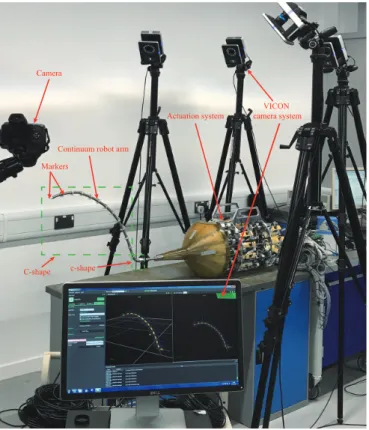
A. An Experimental Layout
To validate the design and development of the continuum robot it is required to perform the C-c configuration shape at the specified curvature and centre. An experimental layout of the built prototype is presented, as shown in Fig. 4, where a VICON optical motion capture system is used to measure the movement with a standard setup for capturing data. Markers are added on small square plates which are mounted on the base of continuum robot arm and the end disks of each section, allowing the tracking of the position and orientation of each marker plate (i.e., represent the base disk frames {Oi}and end-effector frame{O14}). The central point of the
VICON camera system
Continuum robot arm
Actuation system Camera
Markers
C-shape c-shape
Fig. 4. An experimental layout of the continuum robot with VICON camera system.
B. Experimental Test Results
The accuracy of the system is dependent on the precision of the cable actuation, especially as the behaviour of the backbones in the continuum robot can be considered as an open-loop system. Fig.5 compares the desired change in the cable length (solid lines) against the actual (dashed lines) for two sets of cables (i.e., one pair of cables in one body section and a group of three cables in one tip section) in the system while it is performing the C-c shape movement with increasing number of sections. The maximum ∆l in the test was 7.12 mm which produced the maximum error of 0.66 mm (9.3% of the desired). The average error was measured to be less than the 2.5µmstep size of the linear encoder, and therefore the minimal achievable error.
From this experiment it is possible to compare the actuated position against the simulated position of the system. The graph depicted in Fig.6 represents the continuum robot in two poses: the initial position and the full C-c configuration shape. On both poses, the simulated robot is represented as a solid line whilst the VICON data is a dashed line connecting the markers.
There is a notable undershoot from the system. It can be characterised using two methods, by the resulting radius of the curve and the bending angle of the curve. The central point of the curve can be determined from where the normals of each marker plate intersect, while the curvature of each section can be calculated by the relation between neighbouring markers. Furthermore, in Fig. 6, the errors of
0 100 200 300 400 500 600 700
Time (s) -10
-5 0 5 10
∆
Ca
bl
e Cha
nge
(m
m
)
Section 4.1 Section 4.2 Section 13.1 Section 13.2 Section 13.3
Fig. 5. Cable length changes during performing C-c configuration shape (section 4 in body and section 13 in tip were selected as an example to represent).
Horizontal (mm) 0
-50 0
100 50
200 100
150
300
V
ert
ic
al
(m
m
)
200
400 250
300
500 350
600 700 800
Actuated position
Actuated position Initial shape Simulated position
C-c shape Simulated position
Fig. 6. A bending test to perform C-c configuration shape.
radius and curvature between the simulated and actuated positions can be calculated and they are less than 10%, which are theorized to be caused either by slack in the cables or the elastic stretch when under tension. Whilst the tests results in this paper demonstrate that the system is sufficient to meet the requirements in II-A, further work will be focus on improving this performance (e.g., the uneven bend in section 11) by pre-calibration based on the geometry limits of the bevels in disks and force compensation of the cables.
V. CONCLUSIONS
configuration shape bending with max. error of 0.66 mm in actuating the cable length of 7.12 mm and max. deviations of the curve is less than 10%. Thus, this paper presents a slender continuum robot that could be considered as a step forward in providing aeroengine manufacturers with a solution to perform complex tasks.
APPENDIX
As shown in Fig. 3(a) and (b), the distance between the centre of cable hole and Z-axis can be expressed as
di1=|Dr1·sinϕi1| ·sin(θs1)
di2=|Dr1·sinϕi2| ·sin(θs2)
(A.1)
and the angles between the two inclined planes with slope anglesθs1 andθs2can be written as
θ0i=2θs1−∆θi
θ00i=2θs2+∆θi
(A.2)
where the bending angle∆θi can be calculated according to the arc configuration and (1). Thus, the change of gap cable length ∆Li= [∆li1,∆li2,0]T can be obtained as
∆li1=
q
2·di12(1−cosθ0i)− q
2·di12(1−cos 2θs1
∆li2=
q
2·di22(1−cosθ00i)− q
2·di22(1−cos 2θs2)
(A.3)
Therefore, according to A.1 to A.3, 5 can be derived.
ACKNOWLEDGMENT
The research leading to these results has received funding from the Aerospace Technology Institute (UK) under Grant Agreement No. 102360 (FLARE) and Rolls-Royce Plc.
REFERENCES
[1] X. Dong, D. Axinte, D. Palmer, S. Cobos, M. Raffles, A. Rabani, and J. Kell, “Development of a slender continuum robotic system for on-wing inspection/repair of gas turbine engines,” Robotics and Computer-Integrated Manufacturing, vol. 44, no. April, pp. 218–229, 2017.
[2] H. Heckele, F. H¨ahnle, and E. K¨orner, “Surgical instrument for applying implants,” Patent US 6 830 574B2, 2004.
[3] J. Diener, “Instrument for working the surfaces of parts inside engi-neered cavities,” Patent US 5 475 485A, 1995.
[4] G. Chirikjian and J. Burdick, “Hyper-redundant robot mechanisms and their applications,”Proceedings IROS ’91:IEEE/RSJ International Workshop on Intelligent Robots and Systems ’91, no. 91, pp. 185–190, 1991.
[5] W. McMahan, V. Chitrakaran, M. Csencsits, D. Dawson, I. D. Walker, B. Jones, M. Pritts, D. Dienno, M. Grissom, and C. D. Rahn, “Field trials and testing of the OcotArm continuum manipulator,”
Proceedings of the 2006 IEEE International Conference on Robotics and Automation (ICRA), pp. 2336–2341, 2006.
[6] R. Buckingham, “Snake arm robots for flexible delivery,”Insight: Non-Destructive Testing and Condition Monitoring, vol. 44, no. 3, pp. 150– 151, 2002.
[7] I. D. Walker, “Continuous Backbone Continuum Robot Manipulators,”
ISRN Robotics, vol. 2013, pp. 1–19, 2013.
[8] X. Dong, M. Raffles, S. C. Guzman, D. Axinte, and J. Kell, “Design and analysis of a family of snake arm robots connected by compliant joints,”Mechanism and Machine Theory, vol. 77, pp. 73–91, 2014. [9] R. Jing, S. Liang, C. Liu, M. Ma, X. Zhang, and R. Liu, “Structure
and mechanical properties of Ti6Al4V alloy after zirconium addition,”
Materials Science and Engineering: A, vol. 552, pp. 295–300, aug 2012.
[10] X. Dong, M. Raffles, S. Cobos-Guzman, D. Axinte, and J. Kell, “A Novel Continuum Robot Using Twin-Pivot Compliant Joints: Design, Modeling, and Validation,” Journal of Mechanisms and Robotics, vol. 8, no. 2, p. 21010, 2015.
[11] D. Palmer, S. Cobos-Guzman, and D. Axinte, “Real-time method for tip following navigation of continuum snake arm robots,” Robotics and Autonomous Systems, vol. 62, no. 10, pp. 1478–1485, 2014. [12] R. J. Webster and B. A. Jones, “Design and Kinematic Modeling of