warwick.ac.uk/lib-publications
A Thesis Submitted for the Degree of PhD at the University of Warwick
Permanent WRAP URL:
http://wrap.warwick.ac.uk/110793
Copyright and reuse:
This thesis is made available online and is protected by original copyright.
Please scroll down to view the document itself.
Please refer to the repository record for this item for information to help you to cite it.
Our policy information is available from the repository home page.
D e s ig n and Im p le m e n ta tio n
o f
Linear P h a se
W ave D ig ita l F ilters
B y
A. P. S. Jones
A thesis subm itted for the D egree of
Doctor o f Philosophy
D epartm ent o f E ngineering
U niversity o f W arwick
S y n o p s i s
A steady increase o f research w ithin the field o f digital sy stem s has resulted ip a w ide acceptan ce o f th e discrete approach to system design. R esearch has p roduced d iscre te tech n iq u es th a t com plem ent tho se alre ad y in use in th e analogu e dom ain. A rap id im p ro vem ent in the p erform ance and av a ila b ility o f d ig ita l hardw are h as prom pted a m ove fro m analogue to d ig ita l sy stem s, esp e cially w ithin the field o f s ig n a l p ro c e s s in g .
T h is th esis considers th e design o f W ave D ig ital F ilters (W D F 's) to satisfy arbitrary m a g n itu d e and p h a s e s p e c if ic a tio n s w ith fin ite w o rd le n g th c o e ffic ie n ts . It describ es the s tru c tu re s and properties o f lad d e r and lattice W D F's related to linear p h ase desig n th ro u g h co e ffic ie n t s e n s itiv ity and n o n m in im u m -p h a se.
T he in itial part o f t h i s thesis c o n c e n tra te s upon the d esig n and co m p ariso n o f o p tim iz a tio n te c h n iq u e s to s a tis fy m a g n itu d e -o n ly and s im u lta n e o u s lo w p ass frequ ency s p e c ific a tio n s upon lad d e r and la ttic e W D F's. E x p erim e n ts confirm the u n s u ita b ility o f th e la d d e r W D F fo r s im u lta n e o u s d e s ig n s b e c a u s e o f th e ir m in im u m -p h a s e c h a r a c te r is tic s . S u c c e s s fu l s im u lta n e o u s lo w p a s s d e s ig n s u p o n la ttic e W D F's w ere a c h ie v e d th rough q uasi-N ew to n alg o rith m s u sin g a dual line tem plate schem e and a w eighted L p -m e tric e r ro r fu n ctio n .
T he All P ass S e c tio n s (A P S 's ) u sed to c o n s tru c t the low p ass la ttic e W D F w ere in v estig ated and a ra n g e o f A P S's c o n sid ered th at w ou ld allo w the lattice W D F s tru c tu re to s a tis fy h ig h p a s s , s in g le b a n d p a s s and d u al b a n d p a s s freq u en c y s p e c ific a tio n s . S p e c ia l c a s e A P S 's for s in g le and dual b a n d p a s s d esig n s w ere generated by a p p ly in g frequency tran sfo rm atio n s to th e 1st and 2nd o rd e r low pass A P S 's. E q u atio n s an d c h a ra c te ris tic s fo r th ese A P S's are d e ta ile d along with a nu m ber o f exam ples o f filter deigns.
T he final area o f th is thesis co n cerns the desig n o f fin ite w o rdlcn gth solu tion s to m a g n itu d e -o n ly a n d s im u lta n e o u s fr e q u e n c y s p e c if i c a t i o n s , ra n g in g fro m lo w pass to dual b a n d p a s s type re sp o n ses. U sing the large w o rd lc n g th so lu tio n s g e n e ra te d th ro u g h t h e q u a s i-N e w to n o p tim iz a tio n t e c h n iq u e s as s ta r tin g co e ffic ie n ts, a H o o k c -J c e v e s direc t sea rch alg orithm w as im p le m en ted to g enerate fin ite w o rd le n g th s o lu tio n s .
T ec h n iq u es d eta ile d in th is thesis pro v id e a m ethod fo r the g en e ratio n o f finite w o rd le n g th c o e f f ic ie n ts th a t s a tis fy a r b itr a ry m a g n itu d e -o n ly and s im u lta n e o u s frequency s p e c ific a tio n s through o p tim iz atio n fo r the lattice W D F's.
C o n t e n t s
T itle P a g e ... i
D edication... ii
Synopsis... i i i C o n t e n t s ... iv
A c k n o w l e d g e m e n ts ... ix
D eclaratio n ... x
A bbreviations... xi
C hapter I In troduction... 1/1 1.1 D iscrete S ystem P ro p e rtie s... 1 / 1 I I I L i n e a r i t y ... 1 /2
I 1 2 S h i f t - I n v a r i a n c e ... 1 /3 1.1.3 S t a b i l i t y ... 1 /3
1.1.4 C a u s a lity ... 1 /3 1.2 Phase and G roup D e la y ... 1 /6
1.2.1 C h ara cteristics o f L in ea r P h a s e ... 1 /1 0
1.2.2 M in im um - and N o n m in im u m -P h a s e ... 1 /1 4 1.3 F in ite W ordlcngth E ffects... 1 /1 6 1.4 W ave Digital F ilter (W DF)... 1 /2 0
1.4.1 C ircu it D e s c rip tio n s ... 1 /2 0 1.4.2 S t r u c t u r e s ... 1 /2 5 1.5 R esea rch O b je c tiv e s ... 1 /2 8 1.6 S u m m a r y ... 1 /2 9
R e f e r e n c e s ... 1 /3 0
C hapter 2 Design A pp roaches... 2 /1 2.1 Existing M ethods... 2 /1
2.2 F ilte r S tr u c tu r e s ... 2 / 2 2.3 Dom ain O p tio n s ... 2 / 6
2.4 C o e ffic ie n t G e n e ra tio n ... 2 /1 1 2.4.1 O p tim iz atio n C o n s id e ra tio n s ... 2 /1 2
2.5 D esign C hoice - S um m ary... 2 /1 8 R e f e r e n c e s ... 2 /1 9
C hap ter 3 Ladder W D F s... 3 /1 3.1 D esign C h o ic e s ... 3 /1 3.1.1 R eference c irc u it o p tio n s... 3 / 2
3 .1 .2 O p tim iz a tio n c o n s id e r a tio n s ... 3 / 4 3.2 L adder W D F equations... 3 / 7
3 .2 .1 I n t e r c o n n e c t i o n ... 3 / 7 3 .2 .2 O v erall sy stem e q u a tio n s ... ... 3 /1 2
3 .2 .3 B uild in g B lo c k s ... 3 /1 7 3 .3 W A V E : two-port W D F design p ro g ram ... 3 /2 2
3.4 E x p e rim e n ta l R e s u lts ... 3 /2 7 3.4.1 M a g n itu d e -o n ly d e s i g n ... 3 /2 7
3 .4 2 S im u lta n e o u s d e s i g n s ... 3 /3 3 3.5 T w o -p o rt desig n c o n c lu s io n s ... 3 /4 1
R e f e r e n c e s ... 3 /4 3
C hap ter 4 Lattice W D F s... 4 /1 4.1 Design O ptions... 4 /1
4 .1 .1 L attice WDF structures... 4 /1
4 .1 .2 O p tim iz a tio n c o n s id e r a tio n s ... 4 / 8 4 .2 L attice WDF eq u a tio n s... 4 /1 1
4 .2 .1 O v erall system e q u a tio n s ... 4 /1 2
4 .2 .2 B uild in g B lo c k s ... 4 /1 8 4 .3 L attice W D F d esig n and analysis s o ftw a re ... 4 /2 1 4 .4 E x p e rim e n ta l R e s u lts ... 4 / 2 4 4 .4 .1 M a g n itu d e -o n ly d e s ig n ... 4 /2 4
4 .4 .2 S im u lta n e o u s d e s i g n s ... 4 / 2 6
4 .5 L attice W D F design conclusions... 4 / 4 3 R e f e r e n c e s ... 4 /4 5
C hap ter 5 WDF Frequency Transform ations... 5 /1 5.1 F requency T ra n sfo rm s... 5 /1
5 .2 F requen cy transform ed lattice W D F e le m e n ts ... 5 / 6 5.3 C h a ra c te r is tic s o f freq u en c y tra n s f o rm a tio n s ... 5 / 1 0 5 .4 D e sig n c o n s id e ra tio n s w ith freq uen cy t ra n s f o rm s ... 5 /2 2
5 .4.1 D e sig n a p p r o a c h e s ... 5 /2 2 5 .4 .2 O p tim iz a tio n c o n s id e r a tio n s ... 5 /2 4
5.5 D e sign e x a m p le s ... 5 /2 6 5 .5 .1 M a g n itu d e -o n ly d e s i g n ... 5 /2 6
5 .5 .2 S im u lta n e o u s d e s i g n s ... 5 /3 6 5 .6 C onclu sions... 5 /4 2
R e f e r e n c e s 5 /4 5
C h ap ter 6 F inite W ordlcn gth D esigns... 6 /1 6.1 Finite W ordlength E ffe c ts ... 6 /1
6.1.1 F req u e n cy d o m a in s im u la tio n ... 6 / 2 6 .1.2 T im e d o m ain s im u la tio n s ... 6 / 1 4 6 .1.3 L attice W D F im p le m e n ta tio n ... 6 / 2 0
6 .2 Design fo r finite w o rd lc n g th ... 6 /2 5 6.2.1 O p tim iz a tio n c o n s id e r a tio n s ... 6 /2 5
6 .2.2 Design te c h n iq u e s ... 6 / 2 7 6 .3 D esign e x a m p le s ... 6 / 2 9
6 .4 C onclusions... 6 /3 7 R e f e r e n c e s ... 6 /3 9
C hapter 7 L attice W D F D esign Exam ple... 7 /1 7.1 I n t r o d u c t i o n ... 7 /1
7 .2 F ilte r S p e c i f i c a t i o n ... 7 / 2 7.3 M ag nitud e-O nly D e s ig n ( I d e a l)... 7 / 6
7 .4 M agnitude-O nly D e sig n (F inite)... 7 / 1 0 7 .5 S im u ltan e o u s D e sig n ( I d e a l) ... 7 /1 2 7 .6 Sim ultaneous D esign (F in ite )... 7 / 1 6
7 .7 Design S um m ary... 7 / 1 9
C hap ter 8 Discussion and C onclusion s... 8 /1
8.1 P ro ject O u tlin e ... 8 /1 8 .2 Sum m ary o f W D F s tru ctu re s and p ro p e rties... 8 / 2 8.2.1 W D F s tru c tu re s ... 8 / 2
8 .2.2 F requency T ra n s fo rm s ... 8 / 3 8.2.3 F in ite W o rdlcn gth Effects... 8 / 3
8.3 Summ ary o f D esign O ptions... 8 / 4 8.3.1 O ptim ization T e c h n iq u es... 8 / 4
8.3.2 W D F Design M e th o d o lo g ies... 8 / 7 8 .4 C onclusions... 8 / 9
8.4.1 W D F's for L in ea r Phase D e sign ... 8 / 9 8.4.2 D esign T e c h n iq u e P erform an ce... 8 /1 2
8.5 Future W ork... 8 /1 3
A ppendix A Tw o-port B uilding B locks... A / l
A 1 S e rie s In d u c to r ... A /2 A2 S eries C a p a c ito r... A /7
A3 S eries T u n e d In d u c to r /C a p a c ito r... A /1 2
A 4 P a ra lle l I n d u c to r ... A /1 7 A5 P ara lle l C a p a c i to r ... A /2 2
A6 P ara lle l T u n e d In d u c to r/C a p a c ito r... A /2 7 A 7 Unit E le m e n t... A /3 2 A8 D esign E x a m p le s ... A /3 4
A8.1 S o urce D e sig n... A /3 4 A 8.2 Load D e sig n ... A /3 8
A8.3 M id d le D e s ig n ... A /4 1
Appendix B D e sig n Program D escriptio ns... B / l
B1 Design P ro g ra m ‘ellip*... B /2 B2 Design P ro g ra m * w d f... B /7
B3 A naly sis P ro g ra m ‘m l t w d f ... B /15
Appendix C Lattice W D F APS M odels (Frequency D om ain)... C /l Cl Highpass A P S M o d els... C /2 C l. l 1st o r d e r Highpass A PS... C /2
C1.2 2nd o r d e r Highpass A P S ... C /3 C2 Single B a n d p a ss APS M odels... C /4 C2.1 2nd o r d e r S ingle B andpass A P S ... C /4
C2.2 4th o r d e r S ingle B andpass A P S ... C /5
C3 Single B a n d sto p APS M odels... C/8 C3.1 2nd o r d e r S ingle B andstop APS... C/8 C3.2 4th o r d e r S ingle Bandstop A P S ... C /9
C4 Dual B an d p ass APS M o dels... C / l 2 C4.1 4th o r d e r Dual Bandpass APS... C / l 2 C4.2 8th o rd e r Dual Bandpass APS... C / l 5
C5 Dual B an dsto p APS M odels... C / l8 C5.1 4th o r d e r Dual B andstop A P S ... C / l8
C5.2 8th o rd e r Dual B andstop A P S ... C/21
Appendix D L attice W D F APS M odels (Time domain)... D / l
D1 Tw o-port A d a p to r M o del... D /2 D2 Lowpass A P S M odels... D/6
D2.1 1st o rd e r Lowpass APS M odel... D/6 D2.2 2nd o rd e r Lowpass APS M odel... D /7
D3 Highpass A P S M o d els... D/8 D3.1 1st o r d e r H ighpass APS M odel... D/8 D3.2 2nd o r d e r H ighpass APS M o d el... D /9
D4 Single Bandpass APS M odels... D /1 0 D4.1 2nd o rder Single B andpass APS M odel... D /1 0
D4.2 4th o rd er S ingle B andpass A PS M odel... D / l l
DS Single Bandstop APS M o dels... D /1 3 D5.1 2nd o rder Single B andstop APS M odel... D /13 D3.2 4th o rder Single B andstop A PS M odel... D /1 4
D6 Dual Bandpass APS M o d els... D /1 6 D6.1 4th o rd er Dual B andpass A PS M odel... D /1 6
D6.2 8th order Dual B andpass A PS M odel... D /18 D7 Dual Bandstop APS M odels... D /2 1 D7.1 4th o rder Dual B andstop A PS M odel... D/21
D7.2 8th order Dual B andstop A PS M odel... D /2 3
A c k n o w l e d g e m e n t s
T h e a u th o r w ould like to ac kn ow ledg e th e h e lp an d su p p o rt o f p e o p le ;
D r S tu art Law son for ideas, d iscussion an d en c o u rag e m en t as
on all aspects o f my thesis.
R ichard G reen for research ideas and CASE aw a rd with M arconi.
T o n y W icks for TM S32010 coding o f my lattice W D F structure and
T he a u th o r would also like to acknow ledge the fin a n c ia l support o f b o d ie s ;
S c ie n tific and E ngineering R esearch C o u n cil
M arconi U nderw ater System s Ltd
W a rw ic k U n iv ersity
the fo llow ing
m y sup erv isor
APS's.
the following
D e c l a r a t i o n
T h e work in this th esis h as been discussed in the follow ing c o n fe re n c e papers;
Law son. S. S. and Jones, A. P. S., "D esign o f W ave D igital F illers w ith Prescribed M agnitude and Phase R equirem ents". Proc. ECCTD '89, No. 308, F eb ru a ry 1989, p p l-
5.
Jones, A. P. S. and Law son, S. S., "An Approach to the design o f D ig ital Filters with
P re s c rib e d M ag n itud e and L in e a r P hase C h a ra c te ris tic s ”, 10th S a ra g a C olloquium 'D igital and Analogue F ilters and F ilters S ystem s', M ay 1990, p p 3 /l-4 .
Jo nes, A. P. S., Law son, S. S. and W icks, A., "Design o f Cascaded A llp a s s Structures w ith M ag n itu d e and D elay C o n s tra in ts usin g S im u late d A n n e a lin g and Q uasi-
New ton M ethods", Proc. ISC A S-91, S ingapore, IEEE.
Law son, S. S., W icks, A. and Jon es A. P. S., "Design and Im plem entation o f Cascaded A llp ass D igital F ilter S tru ctu re s with M agnitude and Delay C o n s tra in ts ", IEE Proc.
6th Int. C on f on DSP in C om m unications , Loughborough, 1991, p p31 -33.
W ith in th ese c o n fe re n c e p a p e rs th e au th o r w o u ld like to a c k n o w le d g e the c o lla b o ra tio n , ideas and d is c u s s io n s held with Dr. Law son c o n c e rn in g the nature
and c h a rac teristics o f the W ave D igital F ilter and A. W icks in v o lv in g Sim ulated A n n e a lin g o p tim iz a tio n te c h n iq u e s .
A b b r e v i a t i o n s
T h e fo llow ing th is ab b reviation s are used w ith in th is th esis
VVDF W ave Digital F ilter
D S P D igital S ignal P ro cessin g
L T I L in ea r T im e In v a ricn t
D FT D iscrete F o u rier T ansfo rm
F F T Fast F o u rier T ran sform
L B R L ossless Bounded Real
M A P M axim um A v ailable Pow er
A P S All Pass Section
D T L Doubly T erm inated L ossless
F I R F in ite Im pulse R esponse
I I R In fin ite Im p u lse R espon se
C h a p t e r 1
In trod u ction
D ig ital filters m ay be found in a large range o f d igital s y stem s, from dom estic co m p a ct disc p la y e rs to m issile g u idan ce sy stem s. A lthough the p rin cip les o f a d ig ita l filter are co m m o n across each ap p lica tio n , the p ro p e rties and perform ance
o f a specific d ig ita l fille r will depend upon the operation and requirem ent o f the o v erall system . A d ig ita l filter is designed to a lte r the frequency com ponents o f an
in p u t s ig n a l to a g iv en s p e c ific a tio n . F o r a n u m b er o f a p p lic a tio n s , th is s p e c ific a tio n is o n ly co n c ern e d w ith the m ag n itu d e c h a ra c te ris tic s o f a signal.
H o w e v er, a p p lic a tio n s th at also re q u ire th e p h ase re la tio n s h ip b etw e en the frequ ency c o m p o n e n ts o f a signal to rem ain u nd istorted , are c o n stra in ed to using
d ig ita l filters th at e x h ib it a lin ear p hase ch a rac teristic.
1 . 1
D i s c r e t e
S y s t e m
P r o p e r t i e s
A ny system m ay be d efined as an o p e ra to r o r tra n s fo rm a tio n , ac tin g upon an in p u t to p ro d u c e a co rresp o n d in g o u tp u t. T h e n atu re o f a tran sfo rm atio n is
d eterm in ed by these inputs and outputs. A d iscre te system uses in p uts and outputs th a t are a s e q u e n ce o f sam ples, re p rese n tin g a p a rtic u la r s ig n a l. Any discrete
tra n s fo rm w ould th e re fo re be con stra in ed to pro du ce a d is c re te ou tp u t from a d iscrete input. An in p ut sequence {..., x (i), x (i+ l), x (i+ 2 )... x(j),...} may be considered as a vector, x , o f w hich the "n,h sample" is x(n). T h is may be form ally written as
x » { x(n) } , -oo < n < oo
A d ig ital system w ou ld represent these sign als thro ugh a seq u e n ce built up from
sam p les o f the sig n al taken at a regular tim e interval. T his tim e interval is known as th e sam pling p e rio d , T , and is related to the sam pling freq u ency, Fs . by the
eq uatio n T = 1/FS. If a sequence represents a tim e varying signal then it is usual to
d e fin e the seq u en ces as having a fin ite num ber o f elem ents, N . tak en from when tim e equals zero. U n d e r these definitions, a sequence can be w ritten as,
X » (x(0), x (l), x(2)...x(n)... x(N -l)) . O s n S N -l
F o r every input seq u en ce, x . there will be a corresponding ou tpu t sequence, y . The o p eratio n o f a d is c re te system is therefore to use a set o f ru les or transform ations to c o n v e rt an in p u t s e q u e n c e to th e a p p r o p ria te o u tp u t s e q u e n c e . A
Chapter 1. Introduction page 1/2
ele m e n t o f a sequence in iso lation o r ab o u t previou s input an d /o r ou tpu t sam ples. E x am p les o f these types o f o p erations are g iven in E q .( l .l ) , w here E q .( l .l a ) show s
a s q u a rin g fu n c tio n , E q . ( l . l b ) g e n e ra te s an ou tp u t ele m e n t from a n u m b er o f in pu t ele m e n ts and E q . ( l .l c ) com b ines b o th input and o utp ut elem en ts to calculate th e n ex t o u tp u t elem ent.
y(n) = (x(n ))2 , -oo < n < oo (1 .1 a )
So if x * (..., x (i-l), x(i), x ( i + l ) ....) - > y a {..., (x (i-l))2, (x (i))2, (x (i+ l))2, ...) y(n) = x(n) + x (n -l) - x(n-2) , - o o < „ < o o (1.1b)
So if x = {..., x(i-3), x(i-2), x (i-l), x (i), ...) then
y ( i-l) = x (i-l) + x(i-2) - x(i-3) and y(i) = x(i) + x (i-l) - x(i-2)
y(n) = x (n + l) - 2 x(n) + 4 y(n-l) , -< » < n < o o ( 1 .1 c )
S o if x = {..., x (i-l), x(i), x (i+ l), ...J and y a {..., y (i-l), y(i), y (i+ l), ...} ,
t h e n y(i) = x (i+ l) - 2 x(i) + 4 y (i-l)
I f th e in p u t re p resents a sequence o f s a m p le s separated in tim e, then the present
o u tp u t sa m p le , y (i), m ust correspond in tim e to the p resent input sam ple, x (i). In th is w a y , a tran sfo rm is non -cau sal i f th e p resen t o u tp u t. y (i), re q u ires an input valu e , x ( i- f l) , that, as yet, does not ex ist. T herefore, the transform o f E q .( l .l c ) is
n o n - c a u s a l .
T h e b a s ic stru ctu re o f a discre te system is show n by F ig .(1 .1 ), w here th e o utput s eq u e n ce, y , Eq.(1.2), is related to the input sequence, x , and the transform ation, 01.
* —• —
* [ ]
—»— y
F ig u r e 1.1 D iscrete system w ith transfo rm atio n , 01.
y « * [ x ]
(
1
.
2
)
page 1/3
1 . 1 . 1 L i n e a r i t y
T h is p ro p e rty d e s c rib e s th e re la tio n s h ip b e tw e e n th e in p u t s ig n a l and the co rre s p o n d in g o u tp u t sig n al. L in e a rity m ay be d e fin e d u s in g the p rin c ip le s o f su p e rp o s itio n and sca lin g . A sy stem is lin ear, i f a lin e a r c o m b in a tio n o f input seq u e n ces m aps to a lin ear co m b in atio n o f o u tp u t seq u e n ces. T h erefo re, i f y i ( n ) and y 2 ( n ) are th e re s p o n s e s to in p u t s a m p le s X ) ( n ) and X 2 ( n ) , th ro u g h a
tra n s f o rm a tio n , 91. respectively, then a system w ill b e lin ear i f and only if
9l[ a x j(n ) + b X2(n)] = a 9t[ xi<n>] + b 9t[ X2(n)] ■ a y j(n ) + b y2(n)
fo r arb itrary co n stan ts a and b.
1 . 1 . 2 S h i f t * I n v a r i a n c e
T h is c h a ra c te ris tic d e s c rib e s h o w th e in p u t/o u tp u t re la tio n s h ip v a rie s a s the
input seq u e n ce is sh ifted. A sy stem is sh ift-in v aria n t i f th e resp on se to a shifted v ersio n o f th e in p u t s eq u e n ce, is iden tica l to a sh ifted v e rs io n o f the response
based upon the unshifted input. T his can be d escrib ed as, i f y (n ) = 9 l[ x ( n ) | then 91 is s h i f t - i n v a r ia n t w h e n y(n - nQ) = 9 t( x ( n - n o )] fo r all nD. W h e re the index n is
a s s o c ia te d w ith tim e , then s h ift-in v a ria n c e is d e sc rib e d a s tim e -in v aria n ce.
1 . 1 . 3 S t a b i l i t y
T h e sta b ility o f a tran sfo rm atio n ind icate s how a sy stem w ill behave to a given input. A tran sfo rm atio n is s ta b le i f it p ro d u c es a b o u n d ed ou tp u t sequence for
ev e ry b o u n d e d in p ut s e q u e n c e . T h is is re ferred to a s b o u n d ed in p ut bounded o u tp u t (B IB O ) stable.
1 . 1 . 4 C a u s a l i t y
C a u s a lity in d ic a te s w h e th e r a t r a n s f o rm a tio n c a n be re a lis e d . A c a u s a l
tra n s fo rm a tio n is o n e w ho se p re s e n t o u tp u t d e p e n d s o n ly o n p ast inpu ts and o u tp u ts an d the p resen t input. T h erefo re the tran sfo rm atio n o f E q .(1.3 ) is causal
y(m) ■ { a i x(n) + 82 x (n-l) ♦ 83 x(n-2) + ....
+ b i y(k) ♦ b2 y ( k -l) + b3 y (k -2) ♦ ....] (1.3)
Chapter 1. Introduction page 1/4
T r a n s f o r m a tio n s th a t m ee t th e lin e a r ity an d tim e -in v a r ia n c e re q u ir e m e n ts , satisfy a bro ad class o f D igital Signal P rocessing(D S P ) operations. A dig ita l filter is
an e x a m p le o f a L in ear T im e-Invariant(L T I) s tru ctu re and c a n be describ ed by the tr a n s f o rm a tio n , 91. o f F ig .(1 .1 ) and E q.(1.2). A tran sfo rm atio n can be com pletely
c h a rac terised by its response to the unit im pulse seq u e n ce. 5 . defined as
T h e un it im p u lse response, h , is the output seq u e n ce o f a system w hen the input sequence is the unit im pulse, 5 . T herefore for a transfo rm atio n . 91, its unit im pulse
re sp o n se is defined as
Any s e q u e n ce can be described as a sequence o f scaled unit im pulses delayed by
o ne s a m p le p erio d w ith re s p e c t to each other. A p p ly in g the p ro p e rtie s o f LTI s tru c tu re s , an o u tp u t seq u e n ce, y , can be c o n s tru c te d by sum m ing the system 's s ca le d u n it im p ulse resp o n ses fo r each elem ent o f th e in p ut seq u e n ce, x . T his process is described in E q .(l.S ).
E q .( l.S ) re p re s e n ts th e c o n v o lu tio n o f the in pu t sig n al w ith the s y s te m 's unit
im p u ls e re s p o n s e . U sing th e c o n v o lu tio n o p e r a to r. *, and th e u n it im pu lse re s p o n s e , h . then the output signal, y , o f a system to an input sequence, x . can be ex p re s s e d as
W ith th e d e s c rip tio n o f a L T I s tru c tu re g iv en b y E q .(1 .6 ), the b a s ic discrete s tru c tu re o f F ig.(1 .1 ), can be redraw n for a LTI s tru ctu re and is illu stra ted by
F ig .(1 .2 ) .
o t h e r w i s e n
h(n) » 91 [ 5(n)] -ex» < n < oo ( 1 .4 )
n
y(n) « X x <k > h < n-k). k-0
-oo < n < oo (1 .5 )
y(n) = x(n) * h(n) (1.6)
X
h
F ig u r e 1.2 D iscrete system in term s o f the
A c o n tin u o u s signal o r w aveform described in the tim e dom ain, m ay be redefined in th e freq u en c y d o m ain though the F o u rier tran sfo rm . A tim e d om ain w aveform
and th e c o rre s p o n d in g fre q u e n c y do m ain w a v efo rm , form a F o u rie r tra n s fo rm p air. T h e n atu re and p ro p e rtie s o f F o u rier tran sfo rm p airs are well k n o w n and c a n be ex te n d e d to in c lu d e d is c re te s ig n a ls [3 ]. U sin g th e D is c re te F o u rie r
T ra n sfo rm (D F T ), a tim e d om ain sequ ence, x . may be defined as a series. X , in the fr e q u e n c y d o m ain .
T he d is c re te frequency dom ain is com m only know n as the z do m ain, w here z is a
co m p lex v a ria b le . C o n v ersio n o f a tim e do m ain s eq u e n ce, x , into a z dom ain s e q u e n c e . X . is perfo rm ed th ro u g h the z tran sfo rm . T h e gen eral form s o f the z tra n s fo rm and th e in v e rs e z tra n s fo rm are g iv e n by E q .(1 .7 ) and E q .(1 .8 )
r e s p e c t i v e l y .
w here c re p resents a circ u lar c o n to u r centred at the o rig in o f the z do m ain , lying
in the re g io n o f convergence o f th e function, X (z).
If the com p lex variable, z. is d efined in its polar form as. z * r eJ®. then w hen r = 1
o r Izl = I , the z transform ation is equal to the DFT. U sing this idea, Eq.(1.8) can be m odified to define the inverse z transform when Izl a 1, as
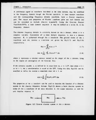
The p ro p e rties o f the z transform can be used to desc rib e the function o f a discrete system in th e discrete frequency dom ain. F ig .(1 .3) sh ow s a basic discrete s y stem in term s o f th e z transform s o f an input sequence, x , the output sequence, y . an d the
unit im p u lse response,
h.
(1 .7 )
(1.8)
x
( 1 .9 )
X(z) H(z) - » --- Y(«>
[image:17.364.22.330.33.418.2]Chapter 1. Introduction page 1/6
The z tran sfo rm o f the un it im pulse response, h , is th e transfer function. H (z ). The re la tio n s h ip o f the tran sfer fu n c tio n to th e in p ut and ou tp u t sequ ences is given
by E q .(l.lO ).
Y(z) « X(z) H(z) (1 .1 0 )
T h e system eq uatio n o f E q .( l .l O ) is the freq uen cy d o m ain equ iv a le n t o f the time dom ain sy stem equation given by Eq.(1.6). From th ese equ ation s it can be seen that
m u ltip lic a tio n in the freq u en c y dom ain is e q u iv a le n t to c o n v o lu tio n in th e tim e d o m a in .
The sy stem eq uatio n s o f E q .(1 .6 ) and E q .(l.lO ) c a n b e re w ritten in term s o f the o p eration s th at occur within th e functions o f h and H (z ), as E q . ( l . l l ) and Eq.(1.12) r e s p e c t i v e l y .
n2
V1
y(n) * 2 * a i x(n- •) * X b i y ( n - i )
i- 0 i- 1
n 2 {U
Y(z) X bi z*i * X (z) 2 - * i ** *
i- 0 i- 0
n 1 num ber o f sam p les in X
n 2 num ber o f sam p les in
y
aj arbitrary co nstan ts, i =0. 1. 2... ni
b i arbitrary co nstan ts, i =1, 2, ti2 and bo
-E q u a tio n (l. 11) show s the g e n e ra l d ifferen ce eq u a tio n fo r a d iscre te sy stem , while E q .(1 .1 2 ) is th e equ iv alent g e n e ra l tran sfer fu n c tio n . E q .(l.lO ) and E q.( 1.12) can
be co m bined to express the tra n s fe r function, H (z), as.
page 1/7
1 . 2
P h a s e a n d G r o u p Delay
F u n c tio n s d e f in e d w ithin the z d om ain are c o m p le x in n atu re . T h e r e fo r e any fu n c tio n , G ( z ), m ay be represented as
G(z) = R e[ G(z) ] + j Im[ G(z) ]
o r in p o la r c o -o rd in ates given in E q .( l.lS ) .
G (z) = I G (z) I (cos (J) + j sin <J>)
G (z) = I G(z) I e J«** w h e r e
(1 .1 4 )
( 1 1 5 a )
( 1 .1 5 b )
«30)1 = V R e[G (z))2 + I m [G (,)] 2 » id 0 » u n > ( j
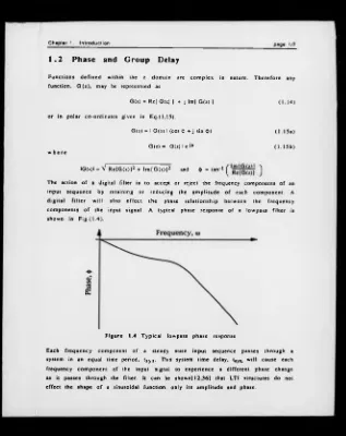
The action o f a digital filter is to accept o r reject th e frequency co m p o n e n ts o f an
in p u t s e q u e n c e by re ta in in g o r re d u cin g th e a m p litu d e o f each co m p o n e n t. A d ig ita l f i l t e r w ill also e f fe c t th e p hase re la tio n s h ip b etw e en th e freq u en c y
co m p o n e n ts o f th e input signal. A typical ph ase re sp o n se o f a lo w p ass filter is show n in F ig .(1 .4 ).
F ig u r e 1.4 T y p ic a l low pass p h a s e response.
E ach fre q u e n c y com p on ent o f a s te a d y state in p u t sequ ence p a s s e s th ro u g h a system in an eq u a l time period, tSys- T his system tim e delay, tsys> w ill c a u se each
[image:19.366.21.338.20.420.2]Chapter 1. Introduction
T h erefo re, if an input fu n c tio n o f the form
x(t) = C sin(o> t)
was applied to a LTI stru c tu re , th en the output w ould be
y(t) = D sin(o) (t - tsys)) = D sin(iot - <J>)
w here th e ratio o f D to C in d ic a te s the ch ange in am plitu de o f th e sine function and the p hase d iffe re n c e b etw e en th e input and o u tp u t v e rs io n s o f the sine
w aveform . F o r a LTI s tru c tu re to retain the p hase inform atio n o f an input signal,
th e p h ase re la tion sh ip b e tw e e n th e frequency co m p o n e n ts o f th at sig nal m ust be p re serv e d . C o n sid e r the in p u t fu n c tio n ,
x(t) = C i sin(coi t) + C2 sin(o>2 t) + C3 sin(o>3 t) (1 .1 6 )
and th e co rresp o n d in g o u tp u t fu n c tio n
y(t) = Di sin(o) 1 ( t - t s y s )) + D2 sin(o>2( t - t s y s )) + D3 sin((03( t - t sy s) ) (1 .1 7 )
U sing the p rin cip les o f s u p e r p o s itio n , the effec t on each frequ en cy co m p onen t o f the fun ction in E q .(1.1 6) c a n be con sid ered in is o la tio n and th en re com bined to prod u ce E q.(1.1 7 ). The in d iv id u a l input freq uency com p o n e n ts o f E q .(1 .1 6 ), along
page 1/9
F ig u r e 1.5 F requency com ponents (a ) © i , (b) © 2 and (c) © 3 o f the
input and output functions g iven in E q .(1 .1 6 ) and (1.17).
From F ig .(1 .5 ), it should be noted that all th e frequ en cy co m po n en ts o f the input fu n c tio n are in phase. F o r the system to p re s e rv e th is p h ase re la tio n s h ip , the freq u en c y co m po n en ts o f the ou tpu t fu n c tio n a r e a ls o re q u ired to b e in phase.
From E q.(1 .1 7 ), this w ill only occur when,
©1 t*y, - ©2 ttys “ “ 3 ttys ■ 0) ttys
T h erefo re, p hase linearity w ill be p reserved if a p h ase chang e, <)>j. at a frequency,
Chapter 1. Introduction page 1/10
A linear phase LTI structure will therefore have the characteristic
<J>(w) = to tsys
L in ea r p hase can be defined in term s o f the phase delay, a(o>), o r th e group delay,
t(<o) . Phase delay is defined as.
<{>(<■>)
a (a ) * - — — -7Ï < to < 71
A s tru ctu re will th ere fo re exh ibit exactly lin ear p hase if a is c o n s ta n t, illustrated in F ig .(1.6 ). G roup d ela y is d efin ed as the n egative d eriv a tiv e o f th e phase with re s p e c t to the frequ ency, so
T(d>) ■ d0(to)
dco ( 1 1 8 )
U sin g E q .(1.1 5 b) and E q.(1.18 ) the group delay can be ex p re s s e d in term s o f the tra n s f e r fu n c tio n , H (z).
In( H(z) ) = ln( I H(z) I ) + j <fr(o>)
dH(z) d u
___ Î___ ,dj.,H (z ) l d ^ )
I H (z ) I dto * J do>
T(«o) d H ( z )~l
du J
( 1 1 9 )page 1/11
1 . 2 . 1 C h a r a c t e r i s t i c s of L i n e a r Phase
F o r exactly lin e a r ph ase,
4>(w) a - a t ) - i c S t o S x
w here a is a co n stan t p hase delay. T o determ ine the natu re o f a transfer function th a t s atisfies th is co n d itio n , H(z) needs to be expressed in term s o f a . This can be ach ieved by co m b in in g Eq.(1 .1 5a) and Eq.(1.7).
T herefore, in o rd e r fo r a system described by h to possess a constant phase delay, o r exactly lin ear phase. Eq.(1.21) m ust be satisfied for all o f the sequence n = 1, N. A possible so lu tion to th is problem is.
F or the unit im pulse response to satisfy E q .(1.22), it m ust be sym m etrical about the sam ple (N + l)/2 o r a . The term , a , in Eq.(1.22) represents the constant angle o f the
phase response o r the p hase delay. C on sider a typical im pulse response, show n by F ig .(1 .7 ), w hich h as an odd num ber o f sam ples. N, and w hich satisfies E q.(1.22).
The phase d ela y , a , w ill be an in teg er and the sym m etry associated with lin ear phase, will o cc u r around a sam ple point equal to the value o f a .
N
H(ei“) = £ h ( " ) e*J“ n = I H (e*“ ) I (c o s(a o i) + j sin(aco) ) n *l
(1.2 0)
T aking the real and im aginary parts o f Eq.(1.20),
N
R e[ H( ei *) ] ■ I H(e->“ ) I cos(aco) = ^ h ( n ) c o s ( c o n )
N
Im [ H (ei“ ) ) = I H(ej“ ) I sin(aco) = £ h <n > s in (a > n )
n = l
t h e n
s in (a o ) ) c o s ( a u )
and where a * 0, then
N
y h (n ) s i n [ ( a - n ) to) ■ 0 (1 2 1)
Chapter 1. Introduction page 1/12
i c e n t r e o f s y m m e try
F ig u r e 1.7 S ym m etric im pulse resp on se w ith an o d d n u m b er o f sam ples.
I f th e n u m b er o f sam ples o f the unit im pulse response is even, then a is no longer an in teg er an d the sym m etry point fo r a lin e a r phase resp on se w ill ex ist between tw o sam ple p o in ts. T his is illustrated by F ig .(1.8).
F ig u r e 1 .8 S ym m etric im p ulse re sp o n se w ith an even num ber o f sam ples.
T he im pu lse re sp o n se sym m etry, in d icate d b y F ig .(1.7) and F ig .(1 .8 ), re la tes to a co n d itio n w h e n the fu n c tio n e x h ib its b o th c o n s ta n t p h ase dela y and co n stan t
g ro u p d elay. H ow ever, a full d efin itio n o f the transfer fu nction,
H(eJ-) - H*(ei°») ei*®> o r H(ei®) - ± I H(ei«*) I ©!♦<•>
sh o w s th at th e im pulse response w ill still p o sse ss lin ear p h ase i f it ex h ib its either
sy m m e try o r a n ti-s y m m e try . T h e a n ti-s y m m e try ca se re la te s to a 'p ie c e -w is e lin e a r' fu n c tio n , which has co n stan t gro u p d e la y but not co n stan t phase delay. In m o st p ra c tic a l d esig n ca s e s , p h ase d ela y is o f no in te re s t. W here th e filter's
im pu lse re s p o n s e cannot be d efin ed by a fin ite num ber o f sam ples, exactly linear p h ase is im p o ss ib le to obtain and the b est that can be achieved is approxim ately
page 1/t3
U sin g th e in fo rm atio n about th e u n it im pu lse respon se s y m m e try , the po sitio n o f
th e p o le s and zeros o f a fu n c tio n e x h ib itin g p h ase lin e a rity c a n be determ in ed. T h e p o s itio n and re la tio n s h ip o f th e z e ro s o f an e x a c tly lin e a r p h ase tran sfer fu n c tio n can be o b serv ed by co n sid erin g a FIR filter. In o rd e r to ex h ib it lin ear
p h ase a tra n s fe r fu nction. H ( z ), m ust p ossess a sym m etry o r an ti-sy m m etry o f its u n it im p ulse response, so
N
H(z) = X h (°) z ' n = h ( l ) + h(2) z"1 + h (3) z-2 + ... n= 1
± h(3)z-(N *2) ± h (2 )z* (N-») ± h ( l ) z - N
T h e plus sig n correspo n ds to a sym m etric response, w h ile the m in u s sign indicates
a n ti-s y m m e try . B eca u se o f th e sy m m e try o f th e u n it im p u ls e re sp o n se , the tra n s fe r fun ctio n. H (z) and its inverse, H ( z -') m ay be related by E q.(1.2 3 ).
H ( r ') - 1 xN H(D <1.23)
E q .(1.23 ) show s that the functions H (z) and H (z'*) are iden tical, ex c ep t for a delay o f N sam p les and ± 1 factor. U n d e r these con d itio n s th e tw o fu n c tio n s m ust posses
id en tica l zero s. T herefore to s atisfy E q.(1 .23 ), the ze ro s o f an ex a ctly lin ear phase s y stem m u st ex ist in s ets that c o m p rise a ze ro and its re cip ro c al about the unit circle, so H (z‘‘) will possess the sam e set o f zeros.
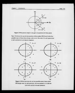
T h is p ro p e rty can be illu s tra te d i f H ( z ) has a facto r. H j( z ) , w h ich is a com plex
co n ju g a te zero pair at r e±J® w hen r * 1 and 0 * 0 o r n, sh ow n in F ig .(1.9 ) by points A an d C. T h e function H ( z - ') w ill have a co rresp o n d in g fu n c tio n H i( z -1). with a
co m p lex co n ju g ate zero p a ir at 1/r e*.!*, show n by points B and D in Fig.(1.9). To
sa tis fy E q .(1 .2 3 ), H (z) and H (z -') m ust possess the sam e zero s and so both functions m u st co n ta in factors to produce the zeros at A . B. C and O o f F ig .(1.9). If a factor H j(z ) p ro d u ces the zeros B and D , then H j ( z '') w ill g en e rate th e ze ro s A and C.
T h e re fo re E q.( 1.23) will on ly be satisfied if H (z) co n ta in s b o th fa c to rs H j(z ) and H j ( z ) , w here H j(z ) = 1 /H j(z). An ex a ctly lin e a r tra n s fe r fu n c tio n m u st th erefo re
Chapter 1. Introduction page 1/14
I m
/ / / / 1
B
' ( l / r , 9)
a. A / (r, ♦) \
c 1 ^
\ X . r . - w/ 1 -0
\ \
s C
1
X
( l / r , -9)
F igu re 1.9 Reciprocal complex conjugate zero positions for linear phase.
F ig.(l.lO ) show s the typical zero positions of linear phase FIR filters for the four possible cases o f linear phase design, odd or even filter order, N, with symmetrical o r anti-symmetrical unit impulse responses.
(c) (d)
F ig u re 1.10 Zero positions for the four possible exactly linear phase
[image:26.367.16.333.27.417.2]1 . 2 . 2 M in im u m -
a n d
N o n m i n i m u m - P h a s e
F ig .(1 .1 0 ) in d icate s the re la tio n s h ip b etw een z e ro s fo r exa ctly lin e a r p h ase FIR
s tru c tu re s . A ll lin e a r p h ase s y s te m s sh o u ld p o s s e s s z e ro s in th e s e ty p e s o f p o sitio n s, w h e th e r FIR o r IIR in n a tu re . IIR stru ctu re s a ls o p o ssess p o le s w ithin th e ir tra n s fe r fu n c tio n s that c o n s tra in the p o s s ib le p o s itio n s fo r its z e ro s . For
so m e IIR s tru c tu re s th e s e c o n s tra in ts m ake it im p o ss ib le to p la c e z e ro s in
re cip ro c al co m p lex co n ju g a te s e ts . T h e co n c ep t o f m in im u m - and n o nm in im um - p h ase can b e applied to a structu re to d ete rm in e i f its zeros can be arran g e d into re q u ir e d p o s itio n s . A fo rm al d e f in itio n o f m in im u m -p h a s e c a n be g e n e ra te d
th ro u g h the H ilbert T ra n sfo rm [2 9 ], o r fo r d is c re te sy s te m s , the D iscrete H ilbert T ra n s fo rm (D H T ).
The DHT provides a m ethod o f re la tin g the real part o f a frequency response in the d is c re te do m ain to its im aginary p art and vice versa. T h ese tw o re la tio n sh ip s form
a DHT pair. I f the z transform , X(z), o f a causal sequence x (n ), is described as
X(ei-) « XR(ei-) ♦ j Xi(ej-)
th en it has th e H ilbert transform p a ir n
x lW“> = ^ P J Xr(«»> CO. ( ^ d *
- I t
a n d
it
xr
(
w
-) - x.o)
-2
* rf
xi<«») cot
- it
w here P den o tes the C au chy p rin c ip le value o f th e in teg ra l! 18].
F or a system . H (ej“ ), to ex hib it m in im u m -p h ase then the com pon ents o f its tran sfer
fu n c tio n s , In[IH (ei“ )l] and arg[H (ei“ )] . m ust form a H ilbert transform pair. T h is may b e re-ex p ressed as
Jt
Chapter 1. Introduction page 1/16
a n d
it
argt H(eJ-) ] = £ P
J
ln [ I H ( e * ) l ] c o l-It
w here tf(z ) = In(H (z)) and li is the F o u rier tran sfo rm p a ir o f ft(z ). A ltern a tiv e ly a
sy stem , H (z ), w ill ex h ib it m inim um -phase if a c a u sal stable inverse sy stem , H **(z), ex is ts such th at
H (z)H 'U ) » 1.
S in c e H - '( z ) = 1/H (z), the transfer function, H ( z ), m ust have all its p o les and zeros in side the unit circ le in o rder for a stab le and ca u sal inverse system to exist.
T h e re q u irem en ts fo r m inim um -ph ase are c o n tra ry to those fo r lin e a r p h ase and th e re fo re , an ex a ctly lin e a r phase sy stem re q u ire s an o v erall n on m inim u m -p hase
s tru c tu re . T h is h o w ev er do es not elim in ate m in im u m -p h a se s tru c tu re s from linear p hase d esig n as any rational function, G (z ), m ay b e ex p ressed in the form
G(z) = Gniin(z) Gap(z)
w here G m in ( z ) <s a m inim um -phase function and G a p (z) is an all-pass function for w hich has IGap(ej“ )l - 1 for all <o.
T h e n atu re o f G a p (z ) is n on m in im u m -p h a se an d th e p o les and z e ro s o f this
fu n c tio n can b e used to produce an o v erall fu n c tio n that m eets the lin e a r phase req u irem en ts. A m inim um -ph ase function can th e re fo re be used in a lin e a r phase
d esig n p ro v id ed the o v e ra ll p hase re sp o n se is m o d ifie d by a p h a s e e q u a lise r. G a p (z ). L in ea r p h ase desig n s throu gh p hase eq u a lis a tio n are d iscu ssed in C hapter 2.
1 . 3
F i n i t e
W o r d l e n g t h
E ff e c t s
A larg e am ount o f research has been d irec ted at the effec ts o f fin ite w ordlength
on d ig ita l s y s te m s , es p e c ia lly fo r d ig ita l f ilte rs . I n itia l w ork by Jac k so n (1 4 ] o u tlin e d a sy stem atic ap pro ach to these fin ite w o rd le n g th effe c ts by d ete rm in in g th e re la tio n s h ip b etw e en ro u n d o ff n o ise and d y n a m ic range. T h is ap p ro a c h o f
F in ite w o rd le n g th effec ts m ay be collec ted u nd er fou r m ain headings;
( i ) C o n v ersio n o f an analogue signal to and from a d ig ita l eq u iv alent. T h is is u su ally know n as co n v e rsio n n oise and w ill d ep e n d upon the
q u a n t i z a t i o n s t e p , b e in g th e d i f f e r e n c e b e tw e e n c o n s e c u t i v e re p re s e n ta b le nu m b ers and th e ty p e o f q u a n tiz a tio n u s e d ; ro u n d in g , v a lu e tru n c a tio n o r m ag n itu d e tru n c a tio n .
( i i ) U n c o rre la tc d ro u n d o ff noise.
T h is is a g eneric term for the n oise introduced to a signal w ith in a Filter d ue to arithm etic operations. The m ain calcu lation to ca u se th is effect is
m u ltip licatio n . T h e bit length to accu rately re p rese n t th e p ro d u c t o f two b b it n um bers is 2b b its. T h is 2 b bit nu m b er ca n n o t be represented w ithin a system lim ited to b bits so the num ber has to be reduced either
th ro u g h ro u n d in g o r tru n c a tio n . T h is in tro d u c e s a ce rta in am o u n t o f u n co rrela te d n o is e into the o p eratio n o f th e filter. T h e v a ria n c e o f this u n co rrela tc d n o ise source w ill d ep en d upon the ty p e o f a rith m e tic used,
flo a tin g o r fix ed point, the sign al lim itatio n sch em e and the type o f n u m b er system used; l 's o r 2’s com p lem en t o r sig n ed -m a g n itu d e .
( i i i ) In a c c u ra c ie s in the filte r resp on se.
T h is n o ise so u rc e re su lts from an in ab ility to ac cu ra tely re p ro d u ce a filte r's freq uen cy response u sin g a fin ite n u m b er o f b its fo r th e filter c o e ffic ie n ts . T h is re su lts in a n o n -id ea l tra n s fe r fu n c tio n . T h is effec t
c a n b e offset i f filter co e ffic ie n ts are d esig n ed to a fin ite w ordlength, re s u ltin g in an a c ce p ta b le Finite w ord le n g th tra n s fe r fu n c tio n .
( i v ) C o rre la te d ro u n d o ff n oise (lim it cy c les).
T w o ty p es o f co rrela te d ro u n d o ff n o ise o r p a ra s itic o s c illa tio n ex ist, sm all scale (g ran u lar) and large scale (overflow ). T hese effe c ts are m ost
a p p a r e n t in fix e d p o in t re c u rs iv e d ig ita l f i l t e r s , w h e re in te rn a l
ro u n d i n g e r r o r s fo r a c o n s t a n t in p u t a r e h ig h ly c o r r e l a te d . Q u a n tiz atio n c a u s e s the no n -lin ea r m apping o f the lo w est o rd e r b its o f
an in tern a l sig n al u nder con stan t in put. T his g en e rate s lim it c y c les. For a re c u rs iv e f ilte r usin g ro u nd ing th is m ean s th a t th e re is n o u nique stead y state ou tp u t fo r a co n stan t in put. A so c a lle d d ea d b an d region
Chapter 1. Introduction page 1/18
L im it c y c le s are dependent upon a num ber o f factors, m ainly the filter realisatio n o r s tru c tu re a n d the q u a n tiz a tio n s tep . S ig n a l q u a n tiz a tio n th ro ug h ro u n d in g is
m o st s u s c e p tib le to lim it c y c le e ffe c ts. M ag n itu d e tru n c a tio n p ro v id es a b e tte r a l te r n a tiv e q u a n tiz a tio n p ro c e d u re , h o w e v e r, it d o e s n o t a lw a y s e lim in a te dead ban d lim it cycles.
F acto rs ( i i ) - ( i v ) are the o nly fin ite w ordlen gth effec ts th at re la te d irec tly to the d ig ita l f i l t e r 's o p eration . In tu rn , each o f th ese e ffe c ts d epend s on the filte r's
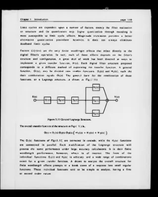
s tru ctu re a n d con figu ration. A gre at deal o f w o rk has been d irec ted at w ays to im plem en t a g iv en tran sfer fu n c tio n . H (z). E ac h digital filte r s tru c tu re pro p osed
co rresp o n d s to a d ifferent m ethod o f ex p ressin g the tra n s fe r fu n ctio n . A gen eral fu n c tio n , G ( z ) , may be d ivided into sm aller fu n ctio n s, G j(z ) and H j(z ), such the
[image:30.366.22.341.22.419.2]th e ir c o m b in a tio n eq uals G ( z ). T he general form for the co m b in atio n o f these functions, o r a Lagrange stru c tu re , is shown in F ig.(1 .1 1).
Figure 1.11 General Lagrange Structure.
The overall transfer function of the structure in Fig.( 1.11) is,
G(z) = G i(z) G 2(z) G3U) ( H i( z ) + H2U ) + H3U ) )
The G i(z ) fu n c tio n s o f F i g . ( l . l l ) arc connected in cascade, w hile the H i(z) fun ctio n s
are c o n n e c te d in p arallel. E ach m o d ific a tio n o f the L a g ran g e s tru c tu re w ill
p o ssess th e s am e p erform ance u n d er large ac curacy ca lcu latio n s. It is th e ir finite w o rd le n g th p e r fo rm a n c e , h o w e v e r, w h ich is o f in te re s t. T he form o f th e in d iv id u a l f u n c tio n s G j(z) and H i(z ) is arbitrary, and a w ide range o f com binations
ex ists fo r a g iv en transfer function. A d esire to analy se the ov erall stru ctu re for finite w o rd le n g th effects prom pts to a break dow n o f a response in to sm all regular
page 1/19
A ca scad e stru ctu re m ay be re p resen ted as
and H2i(z) = 1 + a i j z' 1 + a2i z ' 2 1 + b i J z * l + b2i z" ^
The cascade o f these s e c tio n s also allow s them to be d efined in term s o f functions w hich rep resent the n u m e ra to rs . N j(z) and den o m in ato rs. D i(z). o f each section, so
that H (z) could be expressed as
E q .(1.2 4 ) allow s a cascad ed s tru c tu re to be co nstru c ted from first and second o rder
s e c tio n s w ith arb itrary n u m e ra to r and d e n o m in a to r o rd e rin g s and pairin g s.
A stru cture w hich has a p a ra lle l form , may be ex pressed as,
w here H j(z) is eith er a first o r second order section o f the form.
T he n o ise p ro p e rties o f th e s e 1st and 2nd o rd e r se c tio n s are re la tiv e ly easy to
an a ly se [2 9 ] and the o v erall p e rfo rm an c e o f filte r s tru c tu re s u sin g these elem ents
can b e d eterm in ed . An im p o rta n t o bservation from th is a n a ly sis is th at the o rder and p airin g o f ca scaded s e c o n d o rd e r sectio ns can greatly e ffe c t the overall finite
w o rd le n g th p erfo rm an c e, b e c a u s e o f o v erflow w ith in the s tru c tu re .
A large n u m b er o f filter s tru c tu re s ex ist, each u sin g a d e riv a tiv e o f the g eneral
L a g ra n g e s tru c tu re , i n c l u d i n g th e D irect fo r m s th a t im p le m e n t a tra n s f e r fu n c tio n w ith o u t p a r titio n in g it in to sm a lle r fu n c tio n s . A la rg e am ount o f re search h as bee n d ire c te d at an a ly sin g and co m p a rin g th e s e v ario u s stru ctu re s
Chapter 1. Introduction page 1/20
im p ro v ed th e fin ite w ordlength p erfo rm an c e. A p ro p e rty su g g e s te d to m easure fin ite w o rd le n g th p e rfo rm a n c e co n c ern e d th e s e n s itiv ity o f th e s tru c tu re to
changes in its param eters. Bode defined a s e n s itiv ity fu nctio n, S, to determ ine this p ro p e rty by m ea su rin g how a function , F, c h a n g e s w ith re sp ect to o ne o f its
p a ra m e te rs , x. T h is p ro p e rty , d e fin e d in E q .(1 .2 5 ) , is c o n c e rn e d w ith sm all p aram eter ch a n g es and as a result, sm all s c a le sen sitiv ities.
F x dF
S(F.x) - S; = p - (1 .2 3 )
A n alog u e s tru c tu re s know n to po ssess low p a r a m e te r s e n s itiv ity in clu d e D oubly T erm inated L ossless(D T L ) netw orks. T hese s tru c tu re s s u ffer only a sm all am ount o f d isto rtio n o f th e ir m agnitude respp nses as th e c o m p o n e n ts' v alues are varied. T his
p roperty is related to the ability o f the DTL s tru c tu re to d eliv er m axim um pow er at poin ts ac ro ss its passband.
A t th e s e p o in ts o f M axim um A v a ila b le P o w e r(M A P ), th e d e r iv a tiv e s o f the a tte n u a tio n w ith re s p e c t to re activ e c o m p o n e n ts w ith in th e s tru c tu re are ze ro .
T h erefo re, at th ese M AP points the m ag n itu d e s e n s itiv ity to re activ e com po n ents is zero and b ecau se the sensitiv ity is a s m o o th co n tin u o u s fu nctio n, the sensitiv ity
in the region around these points is also likely to be low. T his effec t, togeth er with a m a t h e m a t i c a l e x p l a n a t i o n , h a s b e e n r e f e r r e d to a s O r c h a r d 's a r g u m e n t[2 6 ,2 7 ,3 7 .2 4 .2 5 ].
In an attem p t to reproduce the properties o f th e analog ue DTL netw o rk in a digital
c irc u it, F ettw eis in v estig ated a num ber o f m e th o d s o f co n v e rtin g a D TL structure in to th e d is c re te d o m ain . T he m etho d a d o p te d by F e ttw e is c o n c e n tra te d upon c re a tin g d ig ita l eq u iv a le n ts o f analogue co m p o n e n ts su ch as an in d u cto r, re sisto r,
v o ltag e so u rc e and tran sfo rm er. F irst by d e s c rib in g the an a lo g u e c o m p o n e n ts in term s o f w ave p aram eters and then c o n v e rtin g them in to th e d ig ita l d o m ain . A
d ig ita l e q u iv a le n t o f the DTL stru ctu re w as th e n co n stru c te d u sin g these dig ita l
c o m p o n e n ts .
T h e re s u ltin g W ave D igital F ilters(W D F ’s) h a s been w id ely re search ed and have
bee n sh o w n to p o s s e s s a s u p e rio r ro u n d o f f n o is e p e rfo rm a n c e c o m p a red to ex istin g d ig ita l filte r structu res[1 7,3 8,1 3,8 ,42 ]. T h e se n s itiv itie s o f W D F's and th eir re feren ce an alog u e D TL filters have also been co m p a red [4 3,28 ] and show n to bear
a c lo s e c o r re la tio n . F u rth e r w ork by F e tt w e i s [ 7 ,6 ,I 0 .2 ] and Jac k s o n [1 3 ) has ad v a n c e d a re la tio n s h ip b etw e en ro u n d o ff n o is e an d a tte n u a tio n c o e ffic ie n t
page 1/21
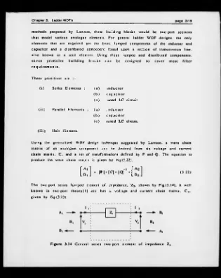
A n a l t e r n a t i v e ap p ro a c h s u g g e s te d by V a id y a n a th a n a n d M itr a [3 9 ,4 0 ,4 1 J
c o n c e rn e d d eriv in g d ig ita l s tru c tu re s in d ep e n d en t o f a n a lo g u e e q u iv a le n ts. The o b je c tiv e o f th is app roach w as to defin e a c la ss o f f u n c tio n based o n the r e q u ir e m e n ts fo r low c o e ffic ie n t s e n s itiv ity an d th en d e r iv e s tru c tu re s based upo n th e s e fu n ctio ns. T he re su lt co n sisted o f tw o -p o rt c h a in m atrice s w hich
d e s c rib in g L ossless Bounded R eal(LBR ) functions. A W D F s tru c tu re s atisfies a LBR fu nctio n an d the results from the two design m ethods are s im ila r in nature.
A co m p a riso n o f various filter structures by M atharu[21] u n d e r a num ber o f finite
w o rd le n g th effec ts, has also been ca rrie d out. The s tru ctu re s u n d er co n sid eratio n
w ere th e lad d er WDF, lattice WDF, unit elem ent W D F, G ray -M a rk el la ttice, d irect form I an d II. cascaded and parallel 2nd o rd e r sections. T h e re s u lts sugg est that c h o ic e o f filte r stru ctu re is not c le a r c u t and is d e p e n d a n t up o n th e filte r a rith m e tic and num bering sy stem . However, in all tests, th e p e rfo rm an c e o f W D F
s tru ctu re s placed them at o r nea r the top o f each com parison list.
1 . 4
W a v e Digital F i l t e r (WDF)
1 . 4 . 1 C i r c u i t
Descr i pt i ons
U sin g a D T L analogue filte r as a reference, F ettw eis b ro k e th e filte r in to its co n s titu e n t elem en ts and m odelled the circ u it as a co n n e ctio n o f o n e-p ort blocks.
A d ig ita l e q u iv a le n t o f e a ch analog ue co m p o n e n t w as th e n g en e rate d and a s tru c tu re co n s tru c te d usin g th ese dig ita l ele m e n ts. F e ttw e is trie d a n u m b er o f d iffe re n t tran sfo rm s to produce digital filters that retained th e p ro p e rties o f th eir
re feren ce s. A successful transfo rm adopted by F ettw eis was to replace th e vo ltag e and c u r re n t description o f an elem ent with an incident and re fle c te d voltag e w ave
Chapter 1. Introduction page 1/22
(1 .2 6 )
In the e q u a tio n s o f E q .(1 .2 6 ), the param eter. A , re p rese n ts th e in cid en t voltag e
w a v e, B th e re fle c te d v o lta g e w ave and R the p o rt re s is ta n c e o f the c irc u it. A p p lica tio n o f th is w ave n o tatio n allow s analog ue com p o nents to be describ ed in term s o f in c id e n t and re fle c te d w aves. A p p ly in g th e z tran sfo rm to analogue
c o m p o n e n t d e s c rib e d in te rm s o f w ave p ara m e te rs , g e n e ra te s a set o f dig ita l e le m e n ts th at c a n b e u s e d to c o n s tru c t d ig ita l s tru c tu re s th at p o s s e s s the p ro p e rties o f th e ir DTL re fe re n c e netw orks.
C o n sid e r the o n e -p o rt e le m e n t in F ig.(1.13). U sing E q .(1 .2 6 ) the reflected v oltage w ave, B, can be d esc rib ed in term s o f the incident voltage w ave. A, port resistance. R, and branch im p ed ance, Z . T his relationship is g iven in Eq.(1.27).
F ig u r e 1.13 O n e -p o rt circuit o f im pedance, Z , in term s o f v o ltag e and c u r re n t and incident and reflected voltage w aves.
A = I ( Z + R)
o r B = A R Z ^ _ R l lL(Z + R )J B = I ( Z - R)
I f the one-po rt b ran ch im p ed an c e. Z, represents a capacitor, C, then
‘ J C u,,u
T he b ilin e ar tran sfo rm is d e fin e d as
r o ' » c - * ) i ' L ( 1 / « C * R) J
(1 .2 7 )
w here T is th e sam plin g period.
2 ( ' ' ■ ' )
T ( « ♦ • ■ • )
( 1 2 9 )
C om binin g E q .(1 .2 8 ) and (1 .2 9 ) then
B = A ( T /2 C - R ) + z - » ( T / 2 C ♦ R )1 .( T /2 C + R ) + z" l ( T / 2 C - R )J
page 1/23
I f the ca p ac itan c e value is redefined as
t h e n
b = a [;
(l/c -
R ) ♦ z- ' n r
+ r i~.(l/c;
+ R ) + z - *( l / C ’ • R ).If the p o rt resistance, R, is set so R ■ I / C , then
B = A z*1
T h e r e fo r e th e dig ita l e q u iv a le n t o f a c a p a c ito r , C . u n d e r the w ave p a ram eter
m ethod sug g ested by F ettw eis, is a u n it d ela y , w ith a port resistance, T/2C . A list o f d ig ita l b u ild in g b lo ck s an d th e ir e q u a tio n s is g iv en in a re v ie w p a p e r by F e ttw e is [I I]. The port re sistan c e p lac es a co n s tra in t upon how the d igital elem ents
m ay b e c o n n e cted . T o use an e le m e n t w ith in a circ u it, the p o rt re sistan c e o f co n n e c te d o n e-p o rts m ust b e iden tica l. H o w e v e r, the port re sistan c e is pred efined
by the m o d elled co m ponent value. T o e lim in a te th is p roblem , F ettw eis also created ad a p to rs to eq u a lise the p o rt re sistan c e b e tw e e n tw o o r m ore d is s im ila r one-po rt e l e m e n t s .
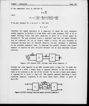
C o n sid e r th e series ca p ac ito r o f the D TL n etw o rk show n in F ig .( l.I 4 ). To m odel this co m p o n e n t in a W DF, a sim p le delay is re q u ire d . H ow ever, to use th is elem ent it
needs to b e connected to the rest o f the netw o rk . T o this end a 3 -port series adapter is re q u ire d and is show n in F ig .( l.I S ) . T h e g en e ral eq u a tio n s d esc rib in g a series
c o n n e c te d c a p a c ito r, e x p re s s e d in its w a v e c h a in m atrix fo rm a t, is g iven by
E q .(l.S O ) .
F ig u r e 1.14 G eneral DTL n etw o rk w ith series ca p ac itor, C.
Vo
N N
[image:35.364.25.334.39.408.2]Chapter 1. Introduction page 1/24
’ A f r < 1 • I ' k i - r i ) ) ( 1 - Y l - Y ï - 2 - ' ( l - Y , ) ) l ‘A3"
( J - T i - T a ) O - i - 1) ( 2 - Y . - Yi) ( 1 - 2 - 1 )
O r , ■ a - ' d - Y i Y i ) ) U - Y . - 2*1)
Lb iJ L ( 2 -y, -t2 ) ( 1 - 2 - 1 ) < 2 - Y | - Y 2 ) ( l - 2 - 1) J Lb3J
It should be noted th at the port resistance R2. o f F ig .( l.l S ) , eq u a ls T/2C, w hile Ri and R3 w ill b e set by th e surro u n d in g circ u it. W hen t h e c irc u it is d esig n ed , h o w e v er, th e actual v alu e s o f R i o r R3 m ay not be p re -s e t and could be chosen
a rb itra rily . In th is ca s e , th e s e values m ay be used to e lim in a te y i o r 7 2- T h re e cases aris e for th is 3-port serie s adapter.
if Yl * 1. Y2 * 1 and R2 » 1/C . t h e n yv = R ^ + R ^ v+ 1 / c , . v - 1.2
o r
if Yi - 1 and R2 - 1/C. t h e n R1 ■ R3 + 1 /C . R i
n ■ R3 + l / C
0 r
if Y2 ■ 1 and R2 * 1/C . t h e n R3 - Rl ♦ 1/ C . Ri
T1 ■ R i ♦ 1 /C
-, ~ 2C
w h e r e C =
U sing th is tech niq ue, the overall com plexity o f a WDF circ u it m ay be reduced. ’ ch a in m a tric e s fo r the d e s ig n cases when Yi = 1 o r Y2 = 1 can be determ ined
su b s titu tio n into E q .(1 .3 0 ). A d eta ile d ex p la n atio n o f th e s e desig n procedures is g iv en in th e re v ie w p a p e r by F ettw eis. T h e fin al d e s c r ip tio n o f the o n e-p o rt c a p a c ito r ele m e n t and a 3 -p o rt series adap ter, g iven by E q .(1 .3 0 ) , was in the form
o f th e w a v e ch a in m a trix . T h e re fo re , th e o rig in a l o n e - p o r t ap p roach w as im p le m en ted w ith in th e circ u it as a tw o-port elem ent.
T h e n e c e s s ity o f usin g a sep a rate ad a p ter c irc u it can be av o id e d if a tw o -port
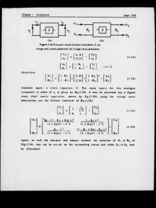
ap proach is used from the s tart. T his techn iqu e w as d e s c rib e d by Law son[19]. An
page 1/25
(■> ( b )
F igure 1.16 Two-port circuit o f series impedance, Z; (a) voltage and current parameters, (b) voltage wave parameters.
t h e r e f o r e
[;/
m
¿si •[;,’]
[
b
a
:
m
: : , ] • [ ; ; ]
—
(1 .3 1 )
( 1 .3 2 )
C o n s id e r a g a in , a s e r ie s c a p a c ito r . C . T h e c h a in m atrix f o r th is a n a lo g u e co m po n en t in term s o f s, is g iv en by E q.(1.33). It m ay be con verted into a d ig ita l w av e c h a in m atrix e q u iv a le n t, sh o w n by E q .(1 .3 4 ) , usin g th e v o lta g e w a v e
d e s c rip tio n s and the b ilin e ar tran sfo rm o f E q .(1 .2 9 ).
" A f r P i - 0 - P1 + P2) I - 1 - B l x ' 1 1 "A 2"
( 1 ♦ p 2 ) ( i - « - ' ) ( 1 ♦ P 2 ) ( l • • - ' )
01 - z * 1 ( 1 - 01 + 0 2 ) - 0 2 z - 1 Lb, J L ( l ♦ p 2 ) ( i • ( i + p 2 ) ( i - i - i ) J Lb2J
( 1 .3 3 )
( 1 3 4 )
A g a in , as w ith th e o n e-p o rt an d a d a p ter m eth o d , th e selec tio n o f R j or R2 o f
F ig .(1 .1 6 ), m ay not be p re-set by th e surrou nd in g c irc u it and eith er P i o r P2 m ay
[image:37.366.22.331.26.437.2]Chapter 1. Introduction page 1/26
p ro v id es three d esig n options.
i f R i a n d R2 a r e
P i R2 + R1 - 1/C* P2 R2 - R1- 1 / C ’
i n d e p e n d e n t t h e n ■ R2 + Rj + 1/C* * " R2 + R i + 1 /C ’
if R2 = R j + 1/C then Pi . " 1 + C 'R i *C O I P2= 0
if R i = R2 + 1 /C then Pi = l + p2. P2" 1 + c rc r22
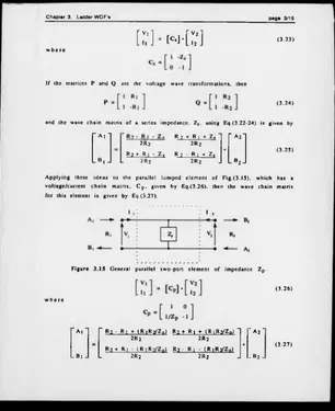
w here C = 2C /T and T is the sam pling period. A fu ll d escription o f these design p rocedures and th eir e ffe c ts on realisation are discu ssed in C hapter 3.
B oth the o n e-p o rt and tw o -p o rt desig n tec h n iq u e s re ly up o n the u se o f v oltage w ave notatio n and the b ilin e a r tran sform . A lthough th is m ethod is w idely used, it
is not th e o n ly m e th o d to p ro v id e a v ia b le s o lu tio n . O th er m e th o d s w ere in v estig ated by L aw so n , w ho proposed a g en e ral W D F co n c ep t u s in g a chain
m atrix o f the form
[ : ; ] -
m
-
i
;
w h e re P and Q are 2 by 2 m a tric e s , th at re p re s e n t a nu m b er o f d iffe re n t t r a n s f o r m a t i o n s ^ , in clu d in g voltage, cu rrent and p o w e r w aves.
1 . 4 . 2 S t r u c t u r e s
DTL netw orks, w hich form the reference filters fo r W D F d esigns, m ay be defined
w ithin tw o groups; lad d e r and lattice stru ctures. T h e g en e ral DTL lad d e r netw ork, show n by F ig.(1.17), is w idely used in analogue c irc u its fo r radio and television as
no elem ent is m ore th an o ne node away from the g ro u nd line and is th erefo re less su sce p tib le to stray ca p ac itan c e.
F ig u r e 1.17 G eneral L ad der N e tw o rk .
T h e s in g le in p u t-o u tp u t path th ro u g h a la d d e r c ir c u it d e te rm in e s th a t the
s tru c tu re h as a m in im um -ph a se c h a ra c te ris tic .
A g e n e ra l la ttic e circ u it, show n by F ig .(1 .1 8 ), p o ssesses m o re than o n e input- o u tp u t p a th , an d m ay th e re fo re be c la s s e d as h a v in g a n o n m in im u m -p h a s e
c h a ra c te ris tic . T h e la ttic e s tru c tu re is m ore g e n e ra lly re d u ced to a b ala n c e d sym m etric form, w here Za ■ Z c and Zb = Z j.
F ig u re 1.18 G e n era l L attice N etw ork.
B oth la d d e r and lattice s tru ctu re s can be u sed as re fe re n c e s for W D F's. T hese d e s ig n s can be app roached through th e o n e o r tw o -p o rt tec h n iq u e s by redu cin g e a ch im p e d a n c e , Z \, into a sim ple ele m e n t, lik e a c a p a c ito r o r an in d u cto r, and
th e n g e n e ra tin g th e a p p r o p ria te W D F c o m p o n e n t. T h e s y m m e tric a l la ttic e stru c tu re , show n in Fig.(1 .1 9 ), bec au se o f its n o n m inim u m -p hase c h a ra c te ris tic , is ideal fo r im p lem en ting allpass functions and is w idely used a s phase e q u a lis e rs in
an a lo g u e d esig n s. L attice stru c tu re s p re sen t p ra c tic a l d e s ig n p ro b lem s, ho w e v er,
b e c a u s e th e p a irs o f b ranch im p e d a n c e s h a v e to be m atch ed w ith in a high to lera n ce. T h is is a difficu lt task as analo g ue com p on ents are hard to a d ju st, and ag e and c y c le w ith tem perature. T h ese effe c ts are not e v id e n t in d ig ita l desig n s
Chapter 1. Introduction page 1/28
T h e sym m etrical la ttic e o f F ig.(1 .19 ), is given in term s o f its canonic im pedances. Z a and Zb- I f th e co rrespo nd ing canonic reflectan ces fo r a sym m etric W D F lattice
are defined as S ' and S", then
‘ Z , ♦ R
Z h • R
w h ere R, bec au se th e stru ctu re is sy m m e trica l, re p rese n ts the p o rt re s is ta n c e o f
each end o f th e lattice. U sing these c a n o n ic re flec ta n ces, a general W D F lattice stru cture can be co n stru cted and is sho w n by Fig.(1.20).
F ig u r e 1.20 G eneral d is c re te sy m m etrical la ttic e with c a n o n ic re fle c ta n c e s .
I f the seco n d in p u t. A2. is set to zero and B i o r B2 ig n o re d , th en th is lattice
s tru c tu re can be s im p lifie d to p ro d u c e a s tru c tu re sh o w n by F ig .(1 .2 1 ). The tra n s fe r fu n c tio n o f th is s tru c tu re w ill then be the sum o r d iffe re n c e o f the
c a n o n ic re f le c ta n c e s .
F ig u r e 1.21 S im p lified sy m m etrical lattice
ca n o n ic re fle c ta n c e s .
B1
B2 S" + S'
2
with
T h e actual im plem entation o f S' and S" is a design param eter. Bartlett! 12] d evised a
m ethod o f g e n e ra tin g a lattice stru ctu re from a sy m m e tric lad d e r n etw ork. The