Comparison of Different Techniques to Design an
Efficient FIR Digital Filter
Amanpreet Singh, Bharat Naresh Bansal
Abstract— Digital filters are commonly used as an essential element of everyday electronics such as radios, cell phones, and stereo receivers. Digital filters may be more expensive than an equivalent analog filter due to their increased complexity, but they may lead to many designs which are impractical or impossible as analog filters. Basically there are two types of digital filters, which are FIR (Finite Impulse Response) and IIR (Infinite Impulse Response). FIR filters are highly desirable in digital filter design because of their inherent stability and linear phase. FIR filters have higher order than IIR filters for same magnitude response, when narrow transition band characteristics are required [1]. In this paper authors have compared their work with the techniques given by R. Mahesh and A.P. Vinod [6] & Z. U. Sheikh [7]. The proposed design by the authors reduce the power consumption of Digital Filter, making it more efficient.
Keywords— FIR filter, Linear phase, Design techniques, coefficient.
I. Introduction
Digital filters are used to modify attributes of signal in the time or frequency domain through the process called linear convolution. Commonly, the term filter is limited to device (hardware or software) that is designed specifically to boost or attenuate regions of a signal spectrum.
With advances in digital technology digital filters are rapidly replacing analogue filters (to be implemented with RLC components). In recent years digital filters have been recognized as primary Digital Signal Processing (DSP) operation, which are typically implemented as multiply-accumulate (MAC) algorithms with use of special DSP devices.
The recent proliferation of portable battery-powered gadgets which make extensive use of Digital Signal Processing (DSP) and demand an ever improving performance like cellular phones, laptop computers etc. has made DSP increasingly important due to low power and high performance. One of the most basic operations performed in DSP applications is Finite Impulse Response (FIR) filtering. An N-tap FIR filter perform the following convolution:
Yj=∑CkXj-k
Dr. Amanpreet Singh: DCOE, PTU, Jalandhar, India, [email protected]
Bharat Naresh Bansal: AP, MIMIT, Malout, India, [email protected]
The Ck’s are called the coefficients of the filter, Xj and Yj are the j-th component of the input and output sequences respectively.
Design techniques for FIR filters can vary widely from one that uses dedicated hardware multipliers and adders to one that uses code and which is executed by a general purpose processor and its ancillary units. There are three significant sources of power dissipation in CMOS circuits; the switching component Psw, the short circuit component Psc and the leakage current component Pleakage or static power Pst. Various techniques have been investigated in the past to control and minimize their contributions to the total power dissipated in CMOS circuits, with the constraint of acceptable performance. Since Psw is often the most significant contributor, efforts have been focused on reducing Psw .These techniques can be grouped into the following four broad categories: a)Technology level b) Circuit level c) Architecture level d)Algorithm level[5].In this paper the authors have proposed a technique which reduces the switching power.
II. Review on Different Design Techniques of
Digital Filter based on Decimation
Eugene B. Hogenauer [2] in their research presented a class of digital linear phase finite impulse response (FIR) filters for decimation and interpolation. They require no multipliers and use limited storage making them an economical alternative to conventional implementations for certain applications. According to him a digital filter in this class consists of cascaded ideal integrator stages operating at a high sampling rate and an equal number of comb stages operating at a low sampling rate. The above configuration is designated cascaded integrator-comb (CIC). Using CIC filters, the amount of passband aliasing or imaging error can be brought within prescribed bounds by increasing the number of stages in the filter. However, the width of the passband and the frequency characteristics outside the passband are severely limited.
comparison to the original filter. This results in to low complexity because of less multiplication and addition. It also results in design of reconfigurable FIR filter design by simply controlling the coefficient.
[image:2.595.328.522.89.221.2]Z. U. Sheikh [7] presented in his work Coefficient decimation technique using linear programming, which gives better results in terms of approximation error than previous work done by R. Mahesh and A.P. Vinod. The comparison of this technique with the previous work in terms of approximation error is given in following table for different value of decimation factor (Dmax) .
TABLE I: MAXIMUM APPROXIMATION ERRORS FOR DIFFERENT Dmax
Dmax Z.U. Sheikh R. Mahesh and A.P. Vinod
1 -55.97dB -55.97dB
2 -55.50dB -47.30dB
3 -55.37dB -47.03dB
4 -55.27dB -45.25dB
III. The Proposed Work
In proposed work, Realization of FIR filter using MATLAB programming has given using the following two techniques: 1) By keeping Nth coefficients of filter unchanged and changing every other coefficient to zero.
2) By keeping Nth coefficients of filter unchanged and removing every other coefficients in between these coefficients.
IV. Simulation Results Based on Both Techniques
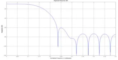
A Filter of order 120 with passband and stopband specifications of fp =0.05 and fs =0.075 is designed using above two techniques. First Simulation results of the first technique is shown
Fig.1 Magnitude response by using Technique of R. Mahesh & A.P. Vinod for N=1
[image:2.595.91.266.253.319.2]Fig.2 Magnitude response by using First Proposed technique for N=1
[image:2.595.325.506.260.375.2]Fig.3 Magnitude response by using Technique of R. Mahesh & A.P. Vinod for N=2
Fig.4 Magnitude response by using First Proposed Technique for N=2
[image:2.595.328.521.415.529.2] [image:2.595.53.268.520.659.2] [image:2.595.308.533.564.678.2]Fig6. Magnitude response by using First Proposed Technique for N=3
Fig.7. Magnitude response by using Technique of R. Mahesh & A.P. Vinod for N=4
Fig.8. Magnitude response by using First Proposed Technique for N=4
First technique was also used by R. Mahesh and A.P. Vinod . According to this technique (i.e. if Nth coefficients remain unchanged and replacing all other coefficients value to zero),
the results based on the research of R. Mahesh and P. Vinod as shown in Fig.1, 3, 5, 7 are
Computation complexity is less.
It has property of re-configurability.
In the design developed by Mahesh and Vinod. If there is increase in the value of N, the stop band ripple deteriorate .
Analysis on the basis of Proposed Work from Fig. 2, 4, 6, 8 is:
The computation required in designing the filter are more, but have better magnitude response.
In the design developed by Mahesh and Vinod, if there is increase in the value of N, the stop band ripple deteriorates, but in the present work stop band ripple variations are less.
Now by using same parameters of the filter, the simulation results of second technique are:
Fig.1 Magnitude response by using Second Proposed Technique for N=1
Fig.2 Magnitude response by using Techniques of R. Mahesh & A.P. Vinod, Z. U. Sheikh, and O. Gustafson for N=1
Fig.4 Magnitude response by using Second Proposed Technique for N=2
Fig.5 Magnitude response by using Techniques of R. Mahesh & A.P. Vinod, Z. U. Sheikh, and O. Gustafson for N=3
Fig.6. Magnitude response by using Second Proposed Technique for N=3
Fig.7. Magnitude response by using Techniques of R. Mahesh & A.P. Vinod,
Z. U. Sheikh, and O. Gustafson for N=4
Fig.8. Magnitude response by using Second Proposed Technique for N=4
The second technique was also used by R. Mahesh & A.P. Vinod and Z.U. Sheikh. According to this technique (i.e. if Nth coefficients remain unchanged and all other coefficients are removed. ), the results from Fig. 2, 3, 5 and 7 are as under:
Required less computation because of less multiplication and addition operations.
Better magnitude response than R. Mahesh and P. Vinod.
It has property of re-configurability.
Analysis on the basis of Second technique of Proposed Work from Fig.1, 4, 6, 8 is:
Requires less computation because of less multiplication and addition operations.
Better magnitude response than R. Mahesh and P. Vinod and Z.U. Sheikh.
It has property of re-configurability.
The magnitude value of the different filter i.e. Proposed Work, Z.U. Sheikh and R. Mahesh & P. Vinod at N=1,2,3,4 are shown in the following table. Table below shows clearly that present work gives better results than other filter.
TABLE II: MAXIMUM APPROXIMATION ERRORS FOR DIFFERENT N i.e. DECIMATION FACTOR
N Proposed Z.U. Sheikh R. Mahesh & P. Vinod
1 -88dB -55.97dB -55.97dB
2 -102.20 dB -55.50dB -47.30dB 3 -102.1 dB -55.37dB -47.03dB 4 -105 dB -55.27dB -45.25dB
The total power of the circuit is the sum of three powers i.e. Dynamic power, Short circuit power and Static power. Major and variable component among above three is dynamic power i.e. Pdyn =½ α fclk V2dd CL, α is switching activity and power consumption mainly depends on this factor. Here, Fclk is clock Frequency, Vdd is dynamic Voltage and CL is equivalent Load capacitance. In the proposed work, the number of computations are less, so less switching activity (α) , which in terms consumes less power and hence less energy.
V. Conclusion
[image:4.595.63.274.354.548.2] [image:4.595.66.263.620.720.2]REFERENCE
[1] Patrick O’Keefe, (2006), “Case Study: Linear-Phase FIR Digital Filter Design Techniques” in Springer, pp. 1-6.
[2] Hogenauer E.B., (1981), “An Economical Class of Digital Filters for Decimation and Interpolation”, IEEE Transactions on Acoustics, Speech and Signal Processing, Vol. no. 2.
[3] Lim Y. C.(1986), “Frequency-response Masking Approach for the Synthesis of Sharp Linear Phase Digital Filters”, IEEE Trans. Circuits Syst.,vol. 33, pp. 357-364.
[4] Mehendale M., Sherlekar S. D., and Venkatesh G., (1995), “Coefficient Optimization for Low Power Realization of FIR Filters”, IEEE Workshop on VLSI Signal Processing, Japan. [5] N. Sankarayya , K. Roy, and D. Bhattacharya, (1997),
“Algorithms for Low Power Fir Filter Realization Using Differential Coefficients,” International Conference on VLSI Design, pp. 174-178.
[6] R. Mahesh and A. P. Vinod (2008), “Coefficient decimation approach for realizing reconfigurable finite impulse response filters,” in Proc. IEEE Int. Symp. Circuits Syst, Seattle, pp. 81– 84.
[7] Z. U. Sheikh, and O. Gustafson (2012), "Linear Programming Design of Coefficient Decimation FIR Filters", IEEE Trans. Circuits Syst. II, vol: 59, issue: 1, pp. 60-64.
Dr. Amanpreet Singh is Deputy Controller of Examination of Punjab Technical University, Jalndhar(India).He has more than 15 years of experience in his field. He has attended more than twenty conference both international and International. He has published more than fifty research papers in international/national conferences and national/international Journals.