Abstract—Dry sliding wear behaviour is fundamentally regarded as an important way of detecting and analyzing the wear characteristics mainly in typical components in the manufacturing industry which has been found to correlate with both safety and cost effective. Thus, wear behaviours were carried out using ball-on-disc tribometer equipment called CETRUMT-2 which operates with linear reciprocating motion. Ball-on-disc test is regarded as one of the most common tests used to study and analyze the wear behaviour. Evaluating the wear volume, and the wear rate of respective samples, ball-on-disc tests were performed on the Universal Micro materials Tester (UMT-2), produced by Centre for Tribology, Inc. (CETR), USA. The wear tests were performed using a tungsten carbide ball of about 10 mm diameter with a constant stroke length of 2 mm together with application normal load of 25 N. The frequency for the reciprocating spindle was maintained at 5 Hz together with speed of 5 mm/s which was also maintained throughout the test. In this paper, the ball-on-disc was used for the investigation of the effects of normal load and hardness of Ti6Al4V-B4C composites on wear behaviour under dry and
sliding conditions. The depths of the worn out section were analyzed from the surface of the sample. The analyzed depths were used to evaluate both wear volume, and wear rate using Archard’s wear model equation. The sample produced at a laser power of 0.8 KW has the lowest wear volume, and wear rate with 35.2 x 10⁻³ mm3 and 6.42 x 10⁻⁴ mm3/Nm respectively, while the sample produced at 2.0 KW experienced the highest wear volume, and wear rate with 93.3 x 10⁻³ mm3 and 26.2 x 10
-4
mm3/Nm respectively.
Index Terms—Ball-on-disc, Linearly reciprocating, Sliding wear, Ti6Al4V-B4C composites, Wear rate
I. INTRODUCTION
HIS Paper studies the effects of normal load on wear behaviour by using the ball-on-disc test under dry condition. Wear can simply be defined as the removal of material from solid surfaces by application of mechanical action [1], [2]. However, several factors are effected on the wear mechanisms, for instance: application of normal load, hardness of material, sliding distance with sliding velocity, and coefficient of sliding friction. Also stated [3] that, wear is a major reliability defect of tribology. Wear is unavoidable in a situation whereby parts are in intimate
Manuscript received July 01, 2016; revised August 01, 2016. Musibau O. Ogunlana is a Masters Candidate in the Department of Mechanical Engineering Science, University of Johannesburg, Auckland Park Kingsway Campus, Johannesburg, South Africa, 2006. (E-mail: [email protected] or [email protected]).
Prof Esther T. Akinlabi is a Professor and the Head of Department in the Department of Mechanical Engineering Science, University of Johannesburg, Auckland Park Kingsway Campus, Johannesburg, South Africa, 2006. Phone: +2711-559-2137, (E-mail: [email protected]).
contact and relative motion. Thus, ball-on-disc test is a fundamental configuration used for wear and friction testing. The amount of wear can therefore be determined by the wear behaviour using the linear dimensions of the specimens after the test has been carried out [4]-[6].
Furthermore, wear is regarded as the progressive damage and material loss which occurs on the surface of a component as a result of its motion relative to the adjacent working parts. Material behaviour is due to mechanical loading which can be broadly classified as being either ductile or brittle. However, under the peculiar conditions generated by intensely loaded point or line contacts, a material may display very different forms of behaviour from those observed under less hard work or continuous physical efforttesting conditions; in particular, because of the intense local compressive stress fields materials which are usually classified as brittle (such as ceramics, B4C) can show significant plastic deformation while those that are ductile (such as titanium alloy, Ti6Al4V) can show greatly enhanced strains prior to failure [7]. Therefore, a common starting point in the analysis of wear is often the Archard’s wear equation which asserts that the wear volume, V is directly proportional to the product of the load, P on the contact and the sliding distance, s but inversely proportional to the surface hardness, H of the wearing material.
It was stated that, Archard was the pioneer in developing the sliding wear model. Archard’s wear equation postulates that the wear rate, K is defined by the volume worn away per unit sliding distance and the load. The wear depth can be evaluated related to the wear rate, sliding distance and contact pressure [7]-[9]. The cogent reason for using this equation is due to its simplified form with easily defined parameters [10].
On the other hand, Titanium and its alloys are extensively used in aeronautical, marine, and chemical industries due to their intrinsic properties such as high specific strength, good oxidation, and corrosion resistance. Nevertheless, the applications of titanium alloys under severe wear conditions are highly restricted due to their low hardness and poor tribological properties such as abrasive wear resistance, poor fretting behaviour, and high friction coefficient [11]-[13]. These researchers [11] however reported the effects of laser nitriding on Ti6Al4V and found that the wear resistance of the treated samples is enhanced noticeably under both two-body abrasive, and dry sliding wear conditions. The results of laser nitriding after plasma spraying of Ni and Cr on the surface of pure titanium show that both sliding and fretting wear resistance were improved greatly. The experiment of laser surface alloying of pure titanium with N2 and CO-mixed reactive gases shows that
Wear Behaviour Characterization of
Ti6Al4V-B
4
C Composites
Musibau O. Ogunlana, and Esther T. Akinlabi, Member, IAENG
the laser alloyed layers exhibit a lower coefficient of friction and a higher wear resistance than as-received sample [11].
Thus, poor fretting behaviour of titanium alloys could be improved and enhanced with the application of surface treatments and coatings. However, these researchers [12] stated that there are four main mechanisms that could be used in improving the tribological behaviour of titanium alloys composites, these include: increase the surface roughness, decrease friction coefficient, increase in hardness, and the induction of a compressive residual stress. Moreso, Boron carbide, B4C has of late assumed great significance as a strategic material because of its high hardness, low density, and high cross section for neutron absorption and chemical inertness. The main applications of this material include: military industries, nuclear industries, solid fuels for rockets, and coating resistant component [14]. Boron carbide is an important nonmetallic material with useful physical and chemical properties. The most important properties of boron carbide include its high temperature stability, high hardness, high cross-section for neutron capture, high modulus of elasticity, low density, chemical inertness, and excellent high temperature thermoelectric properties [14].
Boron carbide is characterized by a unique combination of properties that make it a material of choice for a wide range of engineering applications due to its high melting point and thermal stability which include: it is used as abrasive powders and coatings due to its extreme abrasion resistance, it is excels in ballistic performance due to its high hardness and low density, and it is commonly used in nuclear applications as neutron radiation absorbent [15].
This researcher [16] however reported that, Boron carbide is the third hardest material (Knoop: 2800, 100 g load) next to diamond and cubic boron nitride. Combined with its low weight (density: 2.52 g/cm3), it is the premier material for personal armor. It is used as a nozzle material for slurry pumping and grit blasting because of its excellent abrasion resistance, and for nuclear shielding applications based on boron's high neutron absorption cross section.
Therefore, this research paper presents alloyed layers containing Titanium alloy (Ti6Al4V) and Boron carbide (B4C) on the surface of Titanium alloy (Ti6Al4V) substrate by means of laser metal deposition process thereby investigate the wear resistance of the alloyed layers and the effects of laser processing parameters on the microstructure of the alloyed layers.
II. EXPERIMENTALSETUP
The dry sliding wear tests were carried out using ball-on-disc tribometer equipment called CETRUMT-2 which operates with linear reciprocating motion drive. Analyzing and evaluating the wear volume, and wear rate of respective samples, ball-on-disc tests were performed on the universal micro materials tester (UMT-2), produced by Centre for Tribology, Inc. (CETR), USA. However, the wear tests were performed using a tungsten carbide ball of about 10 mm diameter with a constant stroke length of 2 mm together with application normal load of 25 N. Thus, the frequency for the reciprocating spindle was maintained at 5 Hz
together with speed of 5 mm/s which was also maintained throughout the tests.
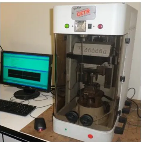
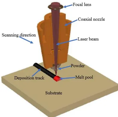
[image:2.595.308.547.200.439.2]Therefore, the dry sliding wear tests were carried out on the single track deposited samples of Ti6Al4V-B4C composites according to the ASTM G133-05 [17]. Figure 1 shows the tribometer equipment used to carry out the dry sliding wear tests. The laser metal deposition (LMD) of the composites was however carried out on the Ytterbium Laser System equipment using a Rofin Sinar, Kuka Robot 3.0 KW maximum power output Ytterbium fibre laser system. Hence, Figure 2 illustrates the diagram of the laser metal deposition process.
Fig. 1: Universal micro materials tester, UMT-2
[image:2.595.309.545.600.757.2]Experiments were conducted at normal load of 25 N with test time of 17 minutes (approximately 1000 seconds). For the constant load application for each sample, sliding speed of 5 mm/s, and sliding distance of 2 mm were observed. The materials which were used in the test were the tungsten carbide disc, and the tests were conducted in ambient air environment without any lubrication applied. Therefore, Table I presented the experimental matrix for the laser metal deposition process.
TABLE I: EXPERIMENTAL MATRIX
Sample designatio
n
Laser power (KW)
Scannin g speed (m/s)
Powder flow rate (rpm)
Gas flow rate (l/min)
EMB1 0.8 0.02 4 2
EMB2 1.0 0.02 4 2
EMB3 1.2 0.02 4 2
EMB4 1.4 0.02 4 2
EMB5 1.6 0.02 4 2
EMB6 1.8 0.02 4 2
EMB7 2.0 0.02 4 2
EMB8 2.2 0.02 4 2
Fig. 2: Schematic diagram of LMD process
A. Physical Appearance of Substrate Material
[image:3.595.319.534.52.188.2]The rectangular Ti6Al4V substrate with dimensions 102 mm x 102 mm x 7 mm was prepared for the laser metal deposition of the mixture powders. Ti6Al4V alloy samples were sandblasted and cleaned under tap water prior to the coating operation. Boron carbide powder, B4C with particle size of about 22-59 μm, and titanium alloy powder with particle size of 45-90 μm, were deposited in the ratio of 1:4 in weight percent. The laser power used were varied between 0.8 KW to 2.4 KW with 0.2 KW interval. The beam diameter or spot size of 4 mm was employed to melt the surface of the samples. Figure 3 illustrates the diagram of the single track deposition substrate.
Fig. 3: Schematic diagram of single track deposit
B. Dry Wear Scar Appearance
The dry sliding wear behaviour observed from the deposited Ti6Al4V-B4C composites was presented in Figure 4. Actual geometry, and shape of the worn-out groove were well understood from the optical microscopic, and scanning electron microscopic analyses. Thus, wear variables observed using wear scar geometry were given as follow: wear depth, wear width, wear track radius, and wear stroke length.
Fig. 4: Schematic of dry wear for worn out surface
III. RESULTSANDDISCUSSION
The materials of the contact pair were titanium alloy (Ti6Al4V) substrate embedded with deposited titanium alloy and boron carbide (Ti6Al4V-B4C) composites adhered to the sliding plate at the lower cylinder part of the test ball. Hence, the geometrical analyses after the test were however observed on the various specimens.
A. SEM Characterization of Wear Track
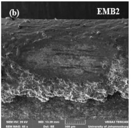
The SEM images of worn scar for respective coatings were shown in Figures 5 (a) and (b). Worn surfaces were characterized using the scanning electron microscope (SEM) equipped with energy dispersion spectrometry (EDS) whereby wear debris and severe wear were observed apparently in all the wear samples. However, the worn surfaces were pronounced by spherical shape in all the samples. Samples EMB1 and EMB2 were pronounced by mild wear when compared to other samples which were due to lower heat input as regards the laser power, and as well as loss of ductility properties within the deposited composites.
[image:3.595.325.538.510.722.2]Fig. 5: SEM images of wear track on the deposited Ti6Al4V-B4C composites: (a) sample EMB1 at laser power
of 0.8 KW; and (b) sample EMB2 at laser of 1.0 KW
B. Wear Surface Behaviour Analysis
Wear volume as well as the wear rate of the linearly operated deposited composites under the normal load application and constantly controlled process parameters were calculated according to Archard’s wear model equations. Thus, Archard’s wear law equations for sliding wear are normally expressed as follows [3]-[5]:
(1)
(2) Where V is the wear volume (mm3), s is the sliding distance (mm), FN is the normal load (N), H is the hardness of the worn surface (HV), and K is the wear rate (mm3/Nm). However, the equation to calculate the wear volume on a flat sample of the linearly sliding wear composites is given as follows:
(3)
Where Vf is the wear volume or material loss (mm3), hf is the wear depth (µm), W is the wear width (µm), Ls is the stroke length of the wear scar (µm), and Rf is the wear track radius of the two spherical ends (µm).
[image:4.595.67.283.50.260.2]The analysis of the wear scar geometry was done with optical microscopy (OM) and then using scanning electron microscopy (SEM) to further implement and consolidate the various parameters involved for the evaluation of wear volume as well as the wear rate. Table II presented the calculated wear variables on deposited coatings of every sample. Moreso, Figure 6 show the behaviour of wear volume, and wear rate of respective samples.
TABLE II: WEAR TRACK VARIABLES EVALUATION
Sample designation
Wear volume (Vf) x 10-3
(mm3)
Wear rate (K) x 10-4
(mm3/Nm)
EMB1 35.2 6.42
EMB2 87.8 19.11
EMB3 76.9 23.57
EMB4 41.3 9.72
EMB5 86.2 23.73
EMB6 89.8 24.61
EMB7 93.3 26.18
EMB8 44.0 11.57
[image:4.595.319.543.330.733.2]EMB9 80.2 23.67
Fig. 6: Relationship between the (a) wear volume; and (b) wear rate of various samples
(a)
Both wear volume and wear rate were characterized by irregular behaviour whereby the samples were observed to experience both increase and decrease as the laser power increases across the deposited composites. From all the deposited composites observed, sample EMB1 deposited at laser power of 0.8 KW has the lowest wear volume of 35.2 x 10⁻³ mm3 while sample EMB7 deposited at laser power of 2.0 KW possesses the highest wear volume of 93.3 x 10⁻³ mm3. Similar to wear volume characteristics, sample EMB1 was also observed to have the lowest wear rate of 6.42 x 10 -4
mm3/Nm while sample EMB7 was however observed to experience the highest wear rate of 26.2 x 10⁻⁴ mm3/Nm.
In addition to these results, it was observed that both wear volume and wear rate were proportional to laser power whereby increase in laser power for respective samples influences both the wear volume and wear rate of the deposited composites. Therefore, this research paper however analyzed the behaviour of wear variables to evaluate the wear volume as well as the wear rate of the specimens. Ball-on-disc wear test is an efficient approach to evaluate both wear volumes, and wear rates of materials using the universal micro materials tester (UMT-2).
IV. CONCLUSION
The wear tests for the deposited composites coating on every samples were conducted using dry sliding wear process on ball-on-disc tribometer equipment. Both wear volume and wear rate for every deposited composites coating samples were calculated using the proposed Archard’s wear equation. For obvious reason, deposited composites sample with laser power of 0.8 KW has the lowest in both wear volume and wear rate, while sample with laser power of 2.0 KW was exhibited to have the highest in both wear volume and wear rate in which the results were attributed to amount of heat input to the deposition, that is, as the laser power increases, the wear volume together with the wear rate experience increase to some extent before decrease to certain level and then rise again. These results were however observed with irregular increase-decrease characteristics in both cases.
REFERENCES
[1] A. Shebani, and C. Pislaru. Wear measuring and wear modelling based on Archard, ASTM, and Neutral network models. World academy of science, Engineering and Technology: International Journal of Mechanical, Aerospace, Industrial, Mechatronic and Manufacturing Engineering, vol. 9, No 1, 2015.
[2] A. Zmitrowicz. Wear Patterns and Laws of Wear - A Review: Institute of Fluid-Flow Machinery, Polish Academy of Sciences, Gdansk. Journal of theoretical and applied mechanics, vol. 44, No. 2, pp. 219-253, Warsaw, 2006.
[3] X. Shen, L. Cao, and R. Li. Numerical simulation of sliding wear based on Archard model, 2010.
[4] J. Qu, and J. J. Truhan. An efficient method for accurately determining wear volumes of sliders with non-flat wear scars and compound curvatures. Journal of wear, vol. 261, pp. 848-855, 2006. [5] S. Sharma, S. Sangal, and K. Mondal. On the optical microscopic
method for the determination of ball-on-flat surface linearly reciprocating sliding wear volume. Department of materials science and engineering, Indian institute of Technology, Kanpur 208016, Uttar, India: Journal of wear, vol. 300, pp. 82-89, 2013.
[6] A. Kumar (107MM034), and S. Singh (107MM037). B Tech thesis: Wear Property of Metal Matrix Composite. Department of
Metallurgical & Materials Engineering National Institute of Technology Rourkela, 2011.
[7] J. A. Williams. Wear modelling: analytical, computational and mapping: a continuum mechanics approach. Cambridge University Engineering Department, Trumpington Street, Cambridge, CB2 1PZ, UK. Journal of wear, pp. 225–229, No. 1–17, 1999.
[8] I. Syafaat, B. Setiyana, Muchammad, and Jamari. Sliding Wear Modelling of Artificial Rough Surfaces. ISSN: 2086-5023, International Journal of Science and Engineering, vol. 4(1), pp. 21-23, 2013.
[9] J. F. Molinari, M. Ortiz, R. Radovitzky, and E. A. Repetto. Finite-element modelling of dry sliding wear in metals. Graduate Aeronautical Laboratories, California Institute of Technology, Pasadena, California, USA; Engineering Computations, vol. 18, No. 3/4, pp. 592-609, 2001.
[10] M. Sarkar, S. K. Ghosh, and P. S. Mukherjee. Determining the Value of Archard’s Co-efficient on the Bottom Plate of Excavator Bucket: An Experimental Approach. In: Proceedings of the 1st International
and 16th National Conference on Machines and Mechanisms (iNaCoMM2013), IIT Roorkee, India, 2013.
[11] Y. S. Tian, C. Z. Chen, L. B. Chen, and J. H. Liu. Wear properties of alloyed layers produced by laser surface alloying of pure titanium with B4C and Ti mixed powders. Journal of Materials Science, vol. 40, pp. 4387–4390, 2005.
[12] M. F. Erinosho, E. T. Akinlabi, and S. Pityana. Microstructures and Dry Sliding Wear Characteristics of the Laser Metal Deposited Ti6Al4V/Cu Composites. In: Proceedings of the 3rd International Conference on Laser and Plasma Application in Material Science, 2015.
[13] R. M. Mahamood, E. T. Akinlabi, M. Shukla, and S. Pityana. Characterization of Laser Deposited Ti6Al4V/TiC Composite Powders on a Ti6Al4V Substrate. Lasers in Engineering, vol. 29, pp. 197-213, 2014.
[14] J. A. Bigdeloo, and A. M. Hadian. Synthesis of High Purity Micron Size Boron Carbide Powder from B2O3/C Precursor. International
Journal of Recent Trends in Engineering, vol. 1, No. 5, 2009. [15] V. Domnich, S. Reynaud, R. A. Haber, and M. Chhowalla. Boron
Carbide: Structure, Properties, and Stability under Stress. Journal of American Ceramic Society, vol. 94, No. 11, pp. 3605–3628, 2011. [16] N. Cho. PhD thesis: Processing of Boron Carbide. School of Materials
Science and Engineering Georgia Institute of Technology, 2006. [17] ASTM Standard G133-05, Standard Test Method for Linearly